1. State-of-the-Art in Piezoelectric Harvesters
Piezoelectric harvesters were proposed and studied by many researchers because of their low cost, light construction, simple production process, and high energy density [156]. Different modes of piezoelectric material are usually used to collect energy from the piezoelectric material depending on the (d33), axial (d31), and shear (d15) modes. A compressive force is applied to the piezoelectric material in the d33 mode, while in the d31 mode the piezoelectric patch is fixed on the console, and vibrations are created in the beam in order to create a bending strain in the piezoelectric patch. In the shear mode, the corresponding force is applied along the y-axis in the yz-plane, while the polarization direction remains along the x-axis [157].
Piezoelectric harvesters were proposed and studied by many researchers because of their low cost, light construction, simple production process, and high energy density [
156]. Different modes of piezoelectric material are usually used to collect energy from the piezoelectric material depending on the (
d33), axial (
d31), and shear (
d15) modes. A compressive force is applied to the piezoelectric material in the
d33 mode, while in the
d31 mode the piezoelectric patch is fixed on the console, and vibrations are created in the beam in order to create a bending strain in the piezoelectric patch. In the shear mode, the corresponding force is applied along the
y-axis in the
yz-plane, while the polarization direction remains along the
x-axis [
157].
In [
157], an PZT energy harvester operating in a shear mode was developed and manufactured to collect the energy of water flowing at varying pressure. The open circuit voltage of 72 mV and the power of 0.45 nW were obtained experimentally at a pressure amplitude of 20.8 kPa and a frequency of about 45 Hz. An analytical mathematical model of voltage generation by a unimorphic piezoelectric cantilever beam based on the classical beam theory was proposed in [
158]. The obtained numerical results of the model are consistent with the experimental results. At the same time, about 24.5 μW of power was obtained in testing at a resonant frequency. It was shown in [
159] that by changing the value and orientation of the magnetic force, the frequency response of a piezoelectric cantilever can be changed in such a way as to provide a useful method for collecting out-of-resonance vibrations.
In [
160], the topology of the PZT energy harvester was presented, consisting of a wind turbine based on an elevator with a PZT beam without a contact vibration mechanism. It has been demonstrated that a power density of 2 mW/cm
3 can be achieved at a voltage of 3.8 V at a wind speed of 0.9 m/s. In [
161], a windmill was constructed having a wind turbine with a horizontal axis and 12 magnets of variable polarity along the periphery. At the same time, a bimorphic PZT element with a size of 60 × 20 × 0.7 mm
3 had a magnet at its end. In this design, a peak electrical power of 450 µW can be achieved with a nominal wind speed of 4.2 miles per hour. In [
162], a rotary harvester was proposed based on the vibration caused by the wind impact. A PVDF piezoelectric beam was used to maintain high deflection during impact. Analytical modeling was developed followed by the use of FE calculations. The maximum power of 2566.4 μW was achieved at a wind speed of 14 m/s.
In [
163], a galloping cantilever beam was developed to collect energy. The beam had a D-shaped cross-section of a piezoelectric sheet bonded in the form of a bimorph. Continuous air supply to the D-shaped section led to abrupt oscillatory movements and, consequently, was converted into electrical energy through a piezoelectric sheet. Experimentally and analytically, a maximum power of 1.14 mW was obtained for the prototype at a wind speed of 4.69 m/s with galloping vibration. In [
164], the PZT generator was modeled as a bending mode using the Euler–Bernoulli beam theory. With a load of 29 kΩ, the maximum power of 6.5 mW has been achieved. In [
165], a cantilever harvester for crosswind was developed. The phenomenon of dropping the tops was used to create vibration of the cantilever beam. This allowed generating 2 W of output power at a resonant frequency.
The energy received from rotating magnets can be increased by expanding the broadband frequency range [
166]. It was shown in [
167] that by using the dynamic magnetic force method, the harvesting power of multi-cantilever beam harvesters can be increased to 55.6%. In [
168], the strain of a prestressed piezoelectric beam caused by interaction with a magnet was used. This harvester was used in the tire pressure monitoring system. A hybrid energy harvester combining piezoelectric and electromagnetic generators has been developed for electronic devices and a wireless system. In [
169], the piezoelectric and electromagnetic methods were combined to make a hybrid energy harvester appropriate for the power requirements of electronic devices, wireless sensors, and nodes. The oscillation of the bimorphic cantilever created an electric potential on piezoelectric surfaces as the relative motion of the magnet disposed on the cantilever end. It induced an electromotive force in the coils in addition to the magnet. About 10.7 mW of power was collected, which is 81.4% higher than that of one electromagnetic harvester. In [
170], a cantilever-type piezoelectric harvester on a shear mode (
d15) was present for collecting energy. The estimated power was approximately 16 mW with an external load of 3 MΩ.
In [
166], rotating magnets were used to increase the broad band frequency range of the energy harvester and increase productivity. In [
171], a vibration-based energy harvester was developed for applications with rotational motion. Beams with proof masses and piezoelectric pads fixed to the beams were installed on the cantilever of rotating hub. Vibration was induced in the beams due to rotation and gravitational influence of the proof masses. Both polyvinylidene fluoride (PVDF) and PZT were used to collect energy at optimal load resistance. The maximum power of 6.4 mW was achieved at a shaft rotation speed of 138 rad/s when using PZT material. In [
172], a cantilever-type harvester was designed, excited by a flow created for heating, ventilation, and air conditioning. Blowing air by hitting the aerodynamic keel fixed at the end of the beam caused vibrations in the beam. As a result, a power of about 3 mW was generated at a flow rate of 5 m/s.
In [
173], a piezoelectric harvester based on a scotch yoke mechanism was developed to convert rotational motion into linear vibrations of two piezoelectric levers through springs. The simulation results showed that for a piezoelectric wind turbine with a blade radius of 1 m at a wind velocity of 7.2 m/s and an estimated angular speed of 50 rad/s, a power of about 150 W can be obtained. In [
174], an octogenerator was proposed for collecting wind energy by using a piezoelectric material. The analytical model made it possible to calculate the power of 5 kW for the device at a tide speed of 1.75 m/s in the ocean.
In [
175], an annular piezoelectric harvester with internal and external concentric rings was developed. The inner ring rotated with some frequency, and the outer ring was stationary to create relative movements between these rings. Piezoelectric pads were installed inside the stationary ring, and each piezoelectric plate magnet was mounted on PZT pads; a magnetic sinusoidal repulsive force was created on the outer periphery of the inner ring during rotation. At an inner ring speed of 30 m/s, the maximum power of 5274.8 W was collected using this device with a radius of 0.5 m.
Thus, the above values of output power in practice may differ by several orders of magnitude. Obviously, full-scale energy-harvesting facilities (in particular, rotary devices) make it possible to significantly expand the output power range observed for low-power electronics, which usually varies from a few microwatts to milliwatts. It could be explained that such an expansion of the range occurred due to fundamentally new design features of macro objects, their complex design, and additional electromagnetic elements of considerable sizes manufactured on the basis of promising materials. The scale factor is characteristic not only for fracture mechanics but also for energy harvesting.
In [
176], the shear mode (
d15) of a cantilever-type piezoelectric bimorphic energy harvester was used to satisfy the Timoshenko beam theory. The developed analytical model gave results close to finite-element modeling. Open circuit peak voltage and power obtained at optimal electric load resistance and operating resonant frequency were observed. Based on the Timoshenko beam theory, an energy harvester, operating in a shear mode (
d15), is presented in [
2]. The cantilever PZT sandwich beam was excited by the vibration of the base, causing shear deformation. It was found that the energy obtained in the
d15 mode was approximately 50% higher than the energy obtained in the
d33 mode. The data [
177] showed that the value of
d15 is greater than the values of
d31 and
d33. Therefore, a shear excitation mode of piezoelectric material should be used to capture power during rotational motion with a simple design of the structure.
2. Some Solutions for Rotary Harvesters
In the last decade, some author’s solutions for rotating harvesters have been researched and developed.
2.1. Rotary Harvester with Parallel Coaxial Plates
In [
178], it was proposed to extract energy from rotating objects using a piezoelectric energy harvester with parallel coaxial plates. The harvester consisted of rotor and stator plates, piezoelectric patches, and magnetic plates (see
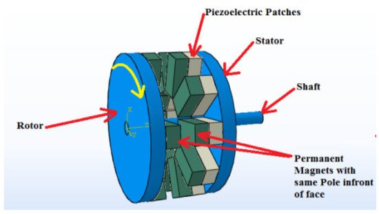
Figure 1). The stator plate had a number of piezoelectric rectangular plates disposed on the inner surface. The surface of the piezoelectric patches was covered with magnetic plates of the same size. The upper plate of the rotor was made of aluminum with an inner surface having number magnetic plates of the same size and shape. The relative angular motion between the stator and rotor created a periodic magnetic repulsion force between the magnet plates. This repulsive force caused compression of piezoelectric patches, which led to the generation of electric charges on the piezoelectric surfaces.
Figure 1. Configuration of piezoelectric energy harvester with parallel coaxial plates (from Narolia et al. [
178], reproduced by permission of Springer Nature © 2022).
A mathematical relation was derived for the RMS power of a piezoelectric energy harvester. The influence of various parameters, such as the sizes of the magnetic and piezoelectric plates, magnetic induction, and rotation velocity, is analyzed. The results showed that the RMS power increased with increasing length and thickness of both the piezoelectric patch and the magnetic plate. The RMS power also increased with an increase in the rotation velocity of the rotor plate and the residual induction of the magnet. Reducing the gap between the stator and rotor plates led to an increase in the RMS power. In this case, the maximum power of 1.3572 W was obtained for a harvester with a radius of 11 mm.
2.2. Rotary Hub Energy Harvester
In [
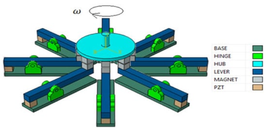
179], a piezoelectric energy harvester with a rotating hub was suggested. This harvester transformed the magnetic attraction force into an electric charge. The magnetic force was induced between the magnets disposed on the hub and the lever located directly below it. The magnetic force on the lever was amplified at the other end, where a piezoelectric rod was installed.
Figure 2 shows the suggested rotary energy harvester with a hub with a vertical axis for energy extraction.
Figure 2. Configuration of energy harvester with rotating hub (from Narolia et al. [
179], reproduced by permission of Springer Nature © 2022).
The main components of the harvester were a rotating hub, eight lever mechanisms with piezoelectric rods, and sixteen magnetic plates. Due to the rotation, the magnetic force on the piezoelectric rod was constantly changing and generating a charge due to the piezoelectric effect. A mathematical model was formulated to calculate the root mean square (RMS) of the power. The influence of various parameters, namely, the thickness of magnets, the thickness and length of the piezoelectric rod, the ratio of the moment arms, and the structural stiffness of the lever on the power and natural frequency of the system, was investigated. An experimental study has shown that the shift mode (d15) can generate power of a higher value than the modes d31 and d33. The maximum power of 113.6684 W was obtained in the harvester. The productivity of the harvester can be increased by increasing the radius of the hub and the number of levers in accordance with the power requirements.
2.3. Shear-Mode Piezoelectric Energy Harvester with Scissor Mechanism
To collect wind energy, it was proposed to excite a piezoelectric material with a shear (
d15) mode [
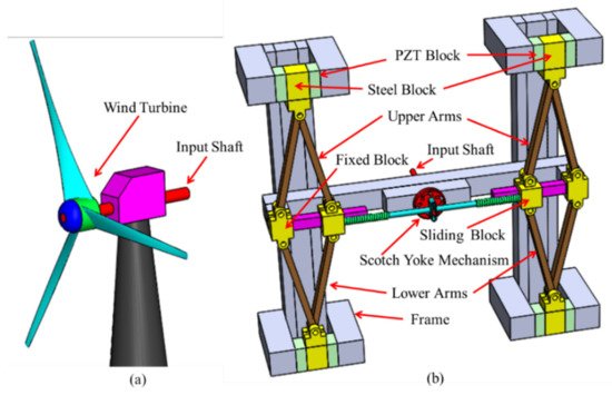
180]. The main parts of the suggested harvester included a windmill, a scotch-yoke mechanism, four piezoelectric pads with two scissor jacks, and two springs. A scissor mechanism with the scotch-yoke mechanism was used to transform the rotational motion of the wind turbine into linear oscillations of the piezoelectric pads. The force of the input spring was changed using a scissor mechanism. The principle of operation of the proposed generator is illustrated in
Figure 3. The rotational motion of the input shaft was transformed into reciprocating motion by means of the scotch-yoke mechanism.
Figure 3. (
a) Configuration of wind turbine and (
b) energy harvester with scissor mechanism (from Narolia et al. [
180], reproduced by permission of Springer Nature © 2022).
To calculate the average electrical power, an analytical model was formulated and modeled. To estimate the effectiveness of the harvester, the wind velocity varied from 5 to 9 m/s. The maximum output power of 242.4 W was calculated at a wind velocity of 9 m/s.
2.4. Shear-Mode Piezoelectric Energy Harvester for Rotational Motion
In [
181], a shear-mode (
d15) piezoelectric energy harvester was designed to collect energy from rotational motion. The assembly of the shear-mode (
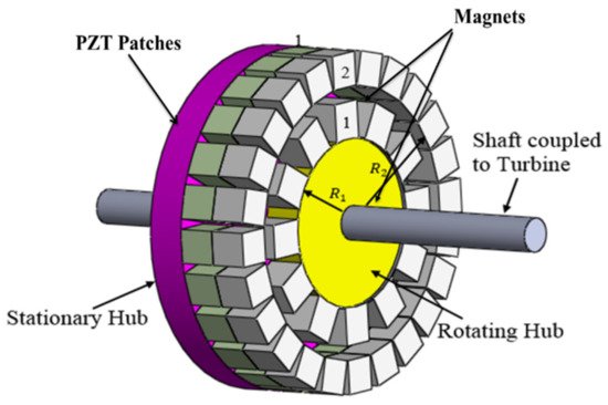
d15) rotary energy harvester is shown in
Figure 4. The harvester consisted of a rotary hub, a stationary hub, and 2
n PZT patches located on a fixed hub. The same number of magnets were located over the PZT patches, and
n magnets of the same size were placed on a stationary hub so that the same poles of the magnets were in front of the face (see
Figure 4). The relative angular motion between the stator and the rotor created a periodic magnetic repulsion force between the magnets and created a shear force on the PZT patches, which led to an electric charge on the surface of the PZT sections to collect energy.
Figure 4. Configuration of energy harvester (from Narolia et al. [
181], reproduced by permission of Journal of Advanced Dielectrics, Vol. 10, No. 03, @ 2020 and World Scientific Publishing Co. Pte. Ltd.).
Mathematical and finite element models were developed to estimate the induced voltage of the piezoelectric patch. The COMSOL Multiphysics 5.3 FEA software was used for the FE simulation, which allowed for the optimization of the various parameters of the harvester. The maximum output power of 358.44 W was calculated for a hub rotation velocity of approximately 600 rpm, with patch sizes of 200 mm × 200 mm × 50 mm and 158 piezoelectric patches.