Energy harvesting technology renders a solution of powering small electronics by harnessing energy from ambient energy sources, such as solar, radio frequency (RF), thermal, and vibration. The rapid development of micro-electronic and micro-electromechanical systems (MEMS) has dramatically reduced the power supply demand. For example, the power consumption of some up-to-date embedded micro-controllers in ultra-low-power mode has been reduced to about 30–250 nW. Therefore, employing energy harvesting technology to provide a sustainable power supply has become possible in a wide range of applications, including wireless remote sensors for structural health monitoring, implanted sensors for medical devices, etc.
1. Energy Conversion Mechanisms
Vibration energy harvesters can be classified into three main categories depending on their energy transduction mechanisms, namely, electromagnetic
[1][2], electrostatic
[3][4], and piezoelectric
[5][6] types.
1.1. Piezoelectric Transduction
The piezoelectric transduction mechanism is based on the piezoelectric effect, which is the capability of certain materials to generate an electric charge on the surfaces in response to applied mechanical stress
[7]. Piezoelectric transducers have the advantages of high-power density and ease of implementation, thus they are widely used for energy harvesting. Moreover, piezoelectric devices could be miniaturized and easily integrated with MEMS technology in a compact form. Therefore, piezoelectric transduction is a suitable choice to meet the miniaturization requirements of future self-powered devices.
1.2. Electromagnetic Transduction
The electromagnetic transduction mechanism refers to Faraday’s law of induction: a voltage difference, sometimes called electromotive force, will be induced in a coil due to any change in the magnetic flux in which the coil is placed. Conventional power plants often realize this transduction mechanism for producing large-scale electricity. The difference is that the generators of power plants are driven by huge heat engines; while small-scale electromagnetic energy harvesters are driven by small ambient vibrations
[2]. Electromagnetic vibration energy harvesters are suitable for scenarios where a relatively large amount of power is required. However, a major disadvantage of electromagnetic transduction is that the dimensions of the energy harvester assembly are usually large because of the need for different parts, such as coils and magnets.
1.3. Electrostatic Transduction
The electrostatic transduction mechanism
[4][8] could be understood through retrospection of the working principle of a parallel-plate capacitor. In a parallel-plate capacitor, its capacitance is proportional to the surface area of the conductor plates and inversely proportional to the separation distance between the plates. On the other hand, capacitance is the ratio of the change in electric charge on the conductor plates over the corresponding change in the electric potential. When the external excitation drives one of the conductor plates to vibrate, the separation distance between the plates would periodically vary. Therefore, if the capacitor is pre-charged with a constrained voltage, the variation of the separation distance between the conductor plates would lead to the generation of currents in the circuit shunted to the parallel-plate capacitor. Instead of pre-charging the electret materials, the researchers can realize triboelectric energy harvesting by coupling the triboelectric effect and electrostatic induction
[9]. Since triboelectric nanogenerators cannot realize energy transduction without electrostatic induction, they can also be deemed to belong to this category.
2. Frequency Up-Conversion Principles
As well-known, a typical linear energy harvester produces a substantial power output only around its natural frequency. However, ambient vibration energy usually spreads over a low-frequency spectrum. To address this challenge, efforts have been devoted to developing mechanical structures with low resonant frequencies for energy harvesting
[10]. In general, there is still a limited number of low-frequency designs due to the challenge of space and size restrictions. Moreover, the aforementioned designs all belong to linear type energy harvesters that have narrow operating bandwidths. Instead of pursuing frequency matching, another idea is to achieve frequency up-conversion, i.e., to convert low-frequency vibrations into high-frequency oscillations. To this end, various means have been proposed in the literature, which can be mainly classified into the following three categories, as listed in
Table 1. More detailed introductions of these means will be presented in the following sections.
Table 1. Classification of frequency up-conversion mechanisms. The orange-colored blocks denote piezoelectric transducers. The black slender blocks denote elastic beams. The dichromatic square blocks denote magnets. To facilitate the graphical illustration, only piezoelectric transduction-based designs are selected.
| Mechanisms |
Methodologies |
Frequency Ranges |
Representative Designs |
References |
Applications * |
Features |
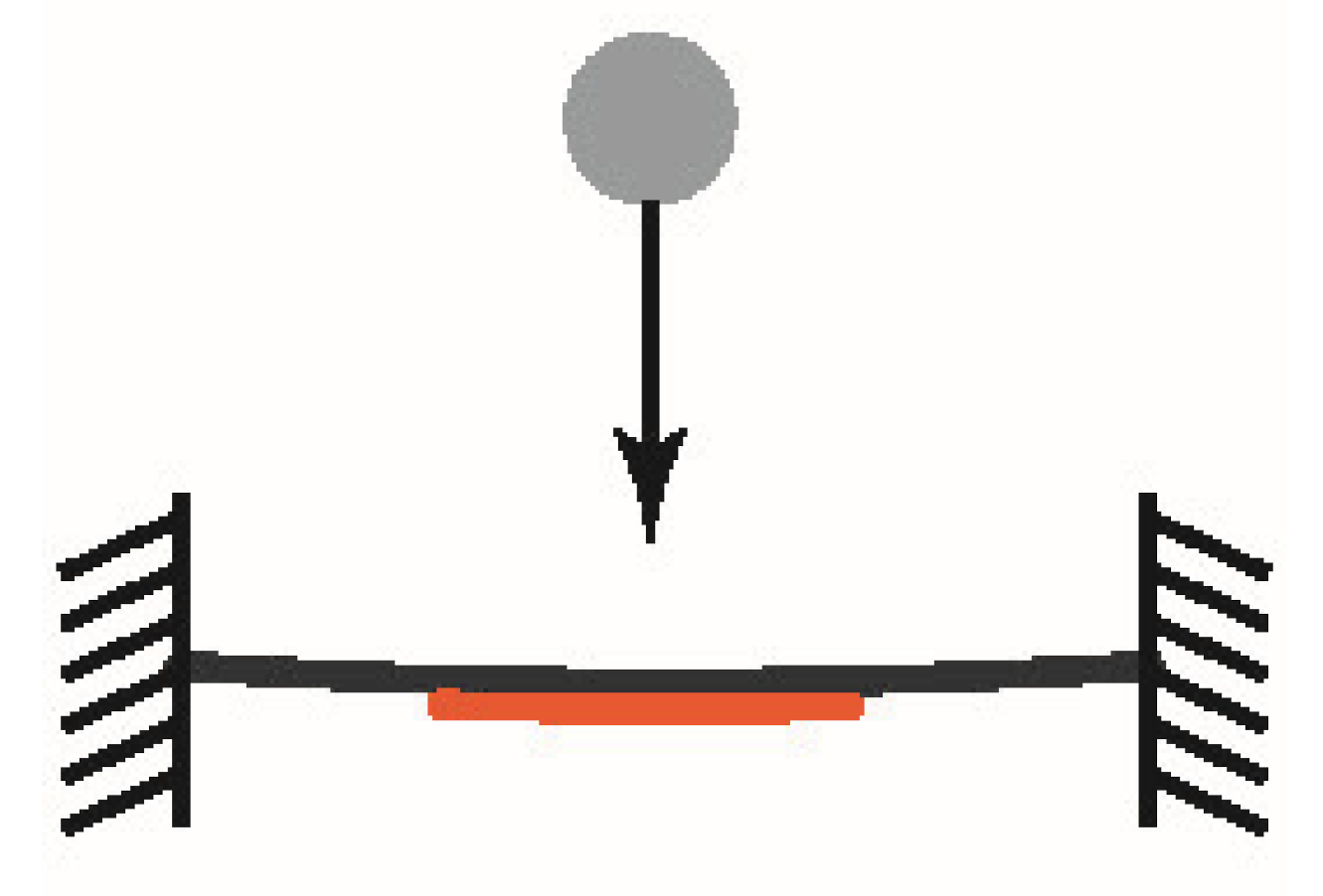
| Impact |
Mechanical impact |
1–50 Hz |
 |
Yang et al. [11]
Halim et al. [12]
Halim et al. [13] |
-
Small-scale wind
-
MEMS
-
Human-limb motion
|
-
Simple
-
Unstable
-
Random output
-
Risk of fracture
|
| Plucking |
Mechanical plucking |
10–50 Hz |
 |
Priya et al. [14]
Pozzi et al. [15]
Tan et al. [16] |
-
Wind flow
-
Knee-joint motion
-
Pavement harvesting
|
-
Compact
-
Robust
-
Miniaturizable
-
Risk of fracture
|
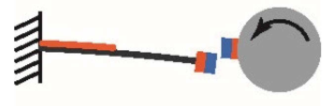
| Magnetic plucking |
10–100 Hz |
 |
Zhao et al. [17]
Kulah et al. [18]
Fan et al. [19]
Kuang et al. [20] |
-
Windmill
-
MEMS
-
Human-limb motion
-
Knee-joint motion
|
| Snap-through |
|
1–30 Hz |
 |
Ando et al. [21] |
|
|
* The applications indicate the applications in the references, rather than the only application scenarios of the methods in those categories.
2.1. Impact-Based Approach
A typical scenario where an impact phenomenon often occurs is a weight falling and striking a target object. During the falling period, with the increase of the falling speed, the gravitational potential energy of the weight is converted into kinetic energy. When impact occurs, the kinetic energy will be transferred to the targeted object in a short instant. Based on this mechanism, if the targeted object is designed as an energy harvester, it will be deformed in a short instant, and some initial energy is stored because of the impact. After the impact is released, the energy harvester starts to undergo an underdamped free oscillation at its natural frequency.
2.2. Plucking-Based Approach
As explained above, in the impact-based approach, the initial kinetic energy is injected by the impacts. After releasing, the energy harvester starts oscillation with an initial velocity. On the other hand, the plucking-based approach has a different mechanism. Plucking refers to the action of pulling an energy harvester forcibly away from its equilibrium by an external force. The external force can be applied through mechanical contact or magnetic coupling. According to the different forms of the applied external force, the plucking-based approach can be further classified into two sub-categories: the former is referred to as the mechanical plucking-based approach and the latter as the magnetic plucking-based approach
[22]. In the plucking design, the plucker bends the structure, so as to input some initial potential energy to the energy harvester structure. After the plucker is released, the energy harvester starts to undergo an underdamped free oscillation at its natural frequency with an initial displacement.
2.3. Snap-Through-Based Approach
Snap-through is a nonlinear phenomenon that can be observed in a bistable system and refers to the action when a bistable system snaps from one stable state to the other. The snap-through phenomenon often occurs along with a large-amplitude inter-well oscillation. As the power output of an energy harvester is normally proportional to the maximum displacement, the large-amplitude inter-well oscillation can significantly improve the energy harvesting performance. Since lots of typical vibration energy harvesters are designed based on beam structures, and a post-buckled beam is convenient for the implementation of a bistable system, buckled piezoelectric beams with snap-through behaviours have been widely explored for vibration energy harvesting.
3. Impact-Based Energy Harvesters
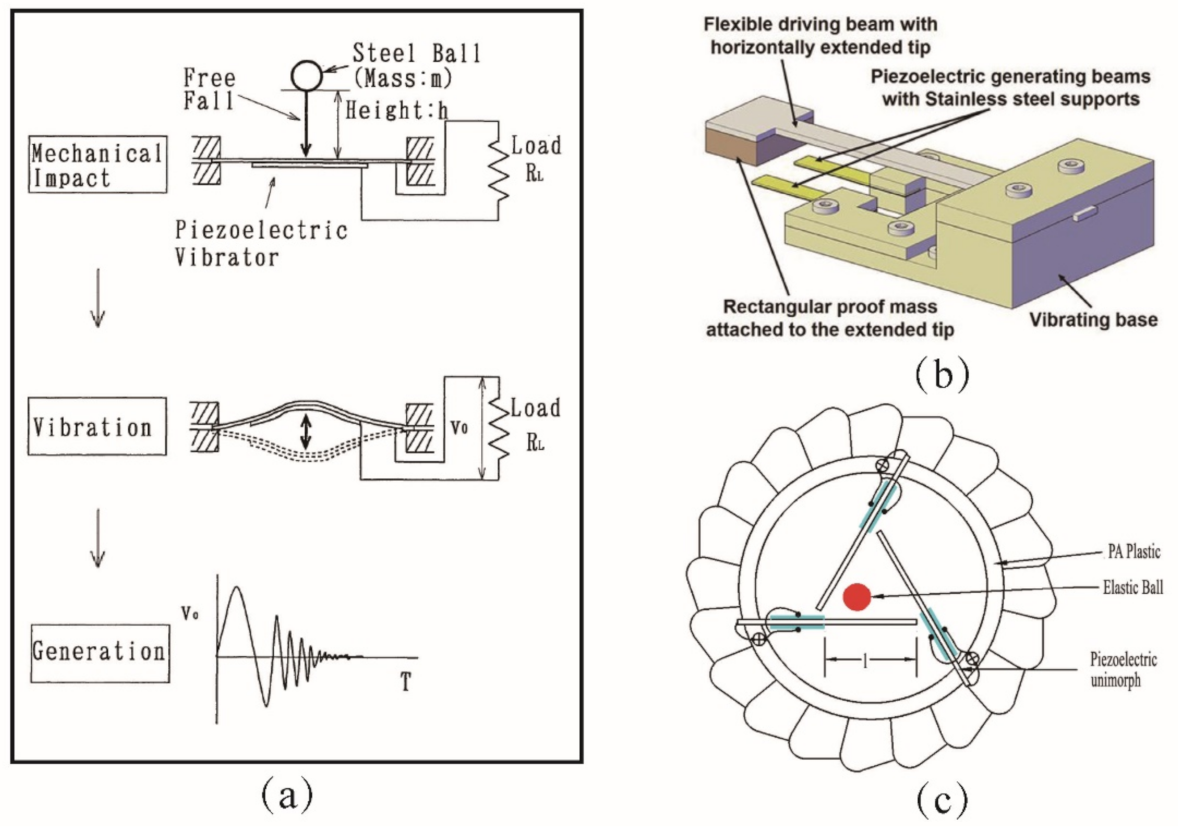
The working principle of mechanical impact-based energy harvester is shown in
Figure 1a. Firstly, the rigid ball is allowed to fall freely onto the centre of the clamped beam under the effect of gravity. After the collision, the kinetic energy of the rigid ball is transferred to the beam. As the sum of all momentums is conserved during collisions, the velocity of the beam becomes non-zero, and the beam starts to vibrate with an initial velocity. Due to the piezoelectric effect, the piezoelectric patch attached to the beam generates voltage output. Umeda et al.
[23] developed an electrical equivalent model of this system to analyse the relationship between the input mechanical impact energy and the output electric energy. Later on, researchers designed various configurations based on the mechanical impact-based structures
[13][24][25][26][27].
Figure 1. Mechanical impact-based energy harvesters. (
a) The principle of mechanical impact
[23]. (
b) A mechanical impact-driven piezoelectric energy harvester
[12]. (
c) An impact-induced rotational piezoelectric wind energy harvester
[11].
Figure 1b demonstrates a mechanical impact-based frequency up-conversion broadband piezoelectric energy harvester designed by Halim et al.
[12][28]. A low-frequency driven beam with a horizontally extended tip mass simultaneously struck two high-frequency piezoelectric generator beams during its vibration. Hence, high-frequency voltage outputs were generated by the two piezoelectric beams. By utilizing impact-induced resonance, Yang et al.
[11] proposed a small-scale energy harvester that could harness energy from winds. As shown in
Figure 1c, when the wind drove the device to rotate, the ball struck the piezoelectric cantilevers; thus, electricity was generated by the piezoelectric transducers. The design enabled each bimorph to be struck in a similar area, but at different moments. It was proved that a relatively stable output frequency could be obtained by the proposed system.
4. Snap-Through Based Energy Harvesters
The working principle of snap-through can be easily understood by referring to the lumped parameter model that consists of two inclined springs and a mass presented in
[29]. Snap-through motion occurs in a bistable structure with two equilibrium states. The rapid transition between the two equilibrium states is referred to as the snap-through motion. Under a large excitation, the bistable system undergoes large-amplitude intra-well oscillation
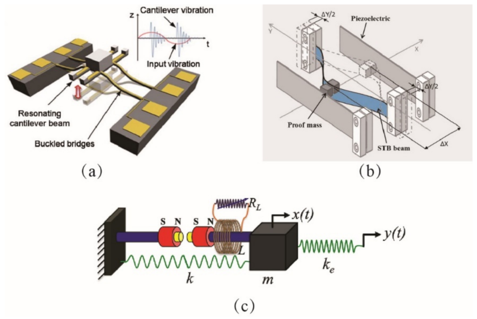
[30]. Jung et al.
[31] designed a snap-through-based piezoelectric energy harvester, as shown in
Figure 2a. The bi-stability was achieved by a buckled bridge structure. A piezoelectric beam was attached to the proof mass of the bistable system. The natural frequency of the piezoelectric beam was higher than the buckled bridge. A single snap-through motion generated an impulse-like excitation to the piezoelectric beam, making it vibrate almost freely at its natural frequency. A similar energy harvester consisting of a buckled bridge and an attached piezoelectric beam was built and investigated by Speciale et al.
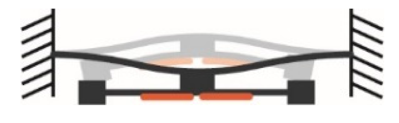
[32]. Instead of attaching the piezoelectric beam to the proof mass of the bistable structure, Ando et al.
[21] placed the piezoelectric beam at the lateral sides of the proof mass, as shown in
Figure 2b. When the bistable system snapped from one equilibrium state to the other, the proof mass rapidly crashed on the lateral piezoelectric beam. The impact was converted to the free vibration of the lateral piezoelectric beam, thus producing an electrical output. The above work all employed piezoelectric transductions. Panigrahi et al.
[33] developed a frequency un-conversion electromagnetic harvester based on the snap-through mechanism.
Figure 2c demonstrates the schematic of the electromagnetic harvester. The bi-stability was formed by the combination of the linear spring and the magnets. The magnet also played the role of inducing the current in the coil during the vibration. The experimental result demonstrated that the response frequency could be increased more than 25 folds due to the employment of the snap-through mechanism. More related work using similar design strategies, as introduced above, can be found in
[34][35][36]. It is worth noting that the snap-through phenomenon itself does not realize frequency up-conversion. The snap-through phenomena are designed to be induced by low-frequency vibrations for producing impulse-like large-amplitude excitations. Harvesters with high resonant frequencies are attached to or placed near the snap-through systems for harnessing impulse-like excitations.
Figure 7. Snap through-based vibration energy harvesters. (
a) A snap-through-based piezoelectric energy harvester
[29]. (
b) A frequency up-converting energy harvester based on snap-through and impact
[21]. (
c) A frequency un-conversion electromagnetic harvester based on the snap-through mechanism
[31].
This entry is adapted from the peer-reviewed paper 10.3390/sym14030631