Your browser does not fully support modern features. Please upgrade for a smoother experience.
Please note this is an old version of this entry, which may differ significantly from the current revision.
Shot peening is a dynamically developing surface treatment used to improve the surface properties modified by tool, impact, microblasting, or shot action.
- cavitation peening
- shot peening
- peening
- cavitation
- additive manufacturing
1. Introduction
The performance of metallic materials such as wear resistance can be improved by applying the appropriate surface treatment. One of the traditional methods of increasing resistance to abrasive wear is so-called shot peening (SP). However, the development of shot peening results in introducing new treatment methods such as cavitation peening (CP). Therefore, it seems essential to characterise the up-to-date peening processes and review their effects on the properties of a surface layer of metal alloys. Currently, the additive manufacturing of metallic components is considered rather modern when it comes to manufacturing technology [1][2][3]. However, the surface of additively constituted parts needs to be finished, and in particular, shot peening can be easily employed.
One of the most promising peening methods is cavitation peening [4][5][6]. The literature systematically studies these peening methods. The crucial application of cavitation peening is the removal of stresses after previous treatments. Exemplary fabrication processes such as milling, forging, or surfacing introduce additional onto the surface layer of the material [7][8], which is harmful to the operational performance of machine components. Therefore, peening can reduce the rate of stress induced by deformation, known as strain hardening. This is the blocking (shortening) of the free path of a dislocation that is in motion in a given plane of the easy slip [9]. The continuous shortening of the free path causes an increase in the plastic flow resistance, which is due to an increase in dislocation density in the peened metals [10]. It is known that heat treatment modifies ductility, hardness, change phase composition, and the grain size of metallic components [11][12]. Therefore, shot peening is considered a competitive process to heat treatment, enabling the required mechanical properties of steel [13][14]. Although, it should be pointed out that, even though most metallic materials can be successfully processed by peening, the limited types of metal alloys undergo heat treatment.
There is a broad range of peening processes reported in the up-to-date literature, and cavitation peening seems to have the highest scientific and industrial potential, which is followed by the literature survey results given in Table 1. An analysis of search results was conducted in Scopus and Web of Science databases for the phrases ‘cavitation peening’, ‘shot peening’, and ‘cavitation peening + shot peening’. There is a noticeable increase in the number of publications in all categories however; according to the information contained in the graphs, the number of publications is the highest for SP, with about 4000 publications, while cavitation peening belongs to a narrower research area, and about 200 publications were devoted to it.
Table 1. Search results for the phrases: cavitation peening (CP), shot peening (SP), and cavitation peening plus shot peening (CP + SP).
| Total Number of Results |
Shot Peening | Cavitation Peening | Shot Peening and Cavitation Peening |
|---|---|---|---|
| WoS | 3824 | 200 | 82 |
| Scopus | 4807 | 194 | 90 |
Recently, much attention has been paid to additive technologies. However, unfortunately, characteristic surface morphology and microstructure features of additively manufactured components can deteriorate the mechanical properties, which consequently need to be improved [15][16][17]. For this reason, various peening methods have been used for finishing machining parts made of metallic materials produced by printing, and combinations of peening methods with other methods, such as heat treatment, are also used [18]. Since parts manufactured using additive manufacturing techniques often have complex shapes, the innovation of additive manufacturing techniques is also important [19]. The surface post-treatment of complex shape components can be efficiently conducted using different shot peening methods. Significantly, the use of cavitation peening seems to make the most sense, due to the possibility of processing locations for working fluid where solid shots cannot reach. Moreover, it is suggested that the combination of shot peening methods, namely hybrid peening in the case of additive manufactured components and the use of lightweight metals such as magnesium alloys and aluminium could pave the way for new, unprecedented solutions by increasing the flexibility of the design process [20]. Unfortunately, limited papers on the peening of additive manufactured metallic materials and literature regarding the hybrid peening of metallic materials is also scant.
2. Shot Peening
Shot peening is a method that has been used since the 1950s. The method was initially used mainly for aviation-related applications. However, it has spread to other industries [21]. Shot peening can improve properties such as the development of surface roughness and hardness [22], improving the resistance to corrosion [23], fatigue [24][25], rolling contact fatigue [24], and fretting [26].
The peening process is carried out in the following manner, and particles with high hardness are accelerated in compressed air or even stream to an appropriate speed, and move towards the component to be burnished. This results in collisions of the particles with the workpiece and other particles. Due to the high hardness of the incident particles, when they hit the surface, their kinetic energy is converted into the plastic deformation of the workpiece. Indentations are produced in the material, and a plastic deformation zone and an elastic zone are formed in the vicinity [21].
During shot peening, the rearrangement of dislocations takes place, which moves from the interior to the vicinity of the grain suit. As the local density of dislocations near the grain boundaries increases, their imbalance also increases. The basis of shot peening is to increase polycrystals’ free energy and generate more defects and interfaces (grain boundaries) through various nonequilibrium processes. Shot peening is a commonly used method to improve the surface layer properties of components, machinery, and equipment. However, shot peening is not a method without disadvantages, including high Ra values, which can partially be removed by grinding or polishing. There are also surfaces that shots cannot reach due to the complex shape of the component [27][28].
To understand the shot peening process, it is vital to know the factors that influence the process. Figure 1 shows the main parameters and factors affecting the process. These are divided into three main subgroups: those related to the medium, the peening equipment, and those related to the work piece. Often, the following are cited as the most important parameters: the peening intensity (frequency) and the area/surface of the shot peening coverage. Many components are subjected to the shot peening process, including turbine blade tips, connecting rods, gears, shafts, axles, springs, and torsion bars. Necessary materials suitable for SP can include high strength steels, aluminium alloys, or isothermally hardened ductile cast iron, and recently also additive manufactured components. Other applications for SP include flutter forming and contour correction. Figure 2 shows a comparison of different surface modification methods.
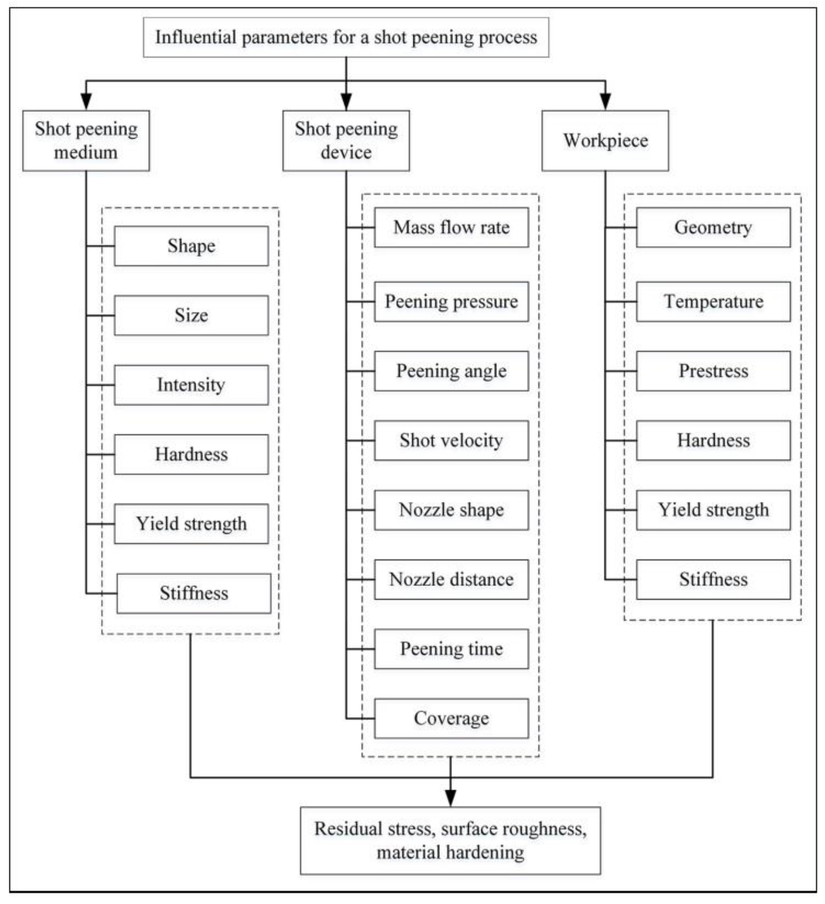
Figure 1. Influential parameters and products of SP [29].
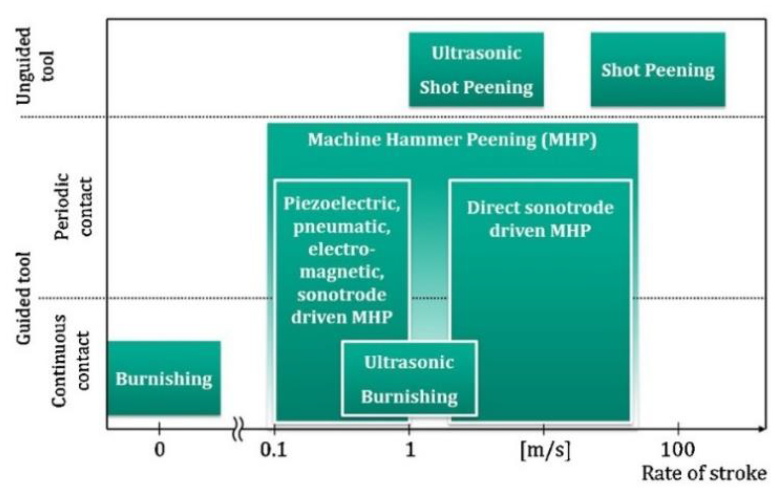
Figure 2. Overview of surface modification processes with guided and unguided tools (reproduced with permission from Ref. [30], Copyright 2016, Elsevier).
3. Peening Methods
There are many methods of coring as well as classifications of these methods. Therefore, this entry focuses on the treatments selected; valid, current, and innovative methods were selected. The shot peening methods described below are also important due to their frequent use, as well as their continuous development and possible further applications.
3.1. Ultrasonic Impact Peening
The method was developed in 1970 in the Soviet shipbuilding industry but was later commercialised under the name Esonix UIT [31]. This method uses an electro-mechanical transducer that generates ultrasonic waves, which are then processed by a piezoelectric or magnetostrictive transducer, and a resonator is set in motion [31][32]. Ultrasonic impact peening is also called ultrasonic hammer peening or direct sonotrode-driven hammer peening. The tool used in this method is a steel pin driven in high-frequency oscillations by an ultrasonic generator. Deburring takes place through the interaction of the tool with the workpiece. The high-frequency impacts create indentations in the material, and thus the material is plastically deformed [33]. Figure 3 shows a comparison of the typical depth of influence between shot peening, laser shock peening, deep rolling, and hammer peening.
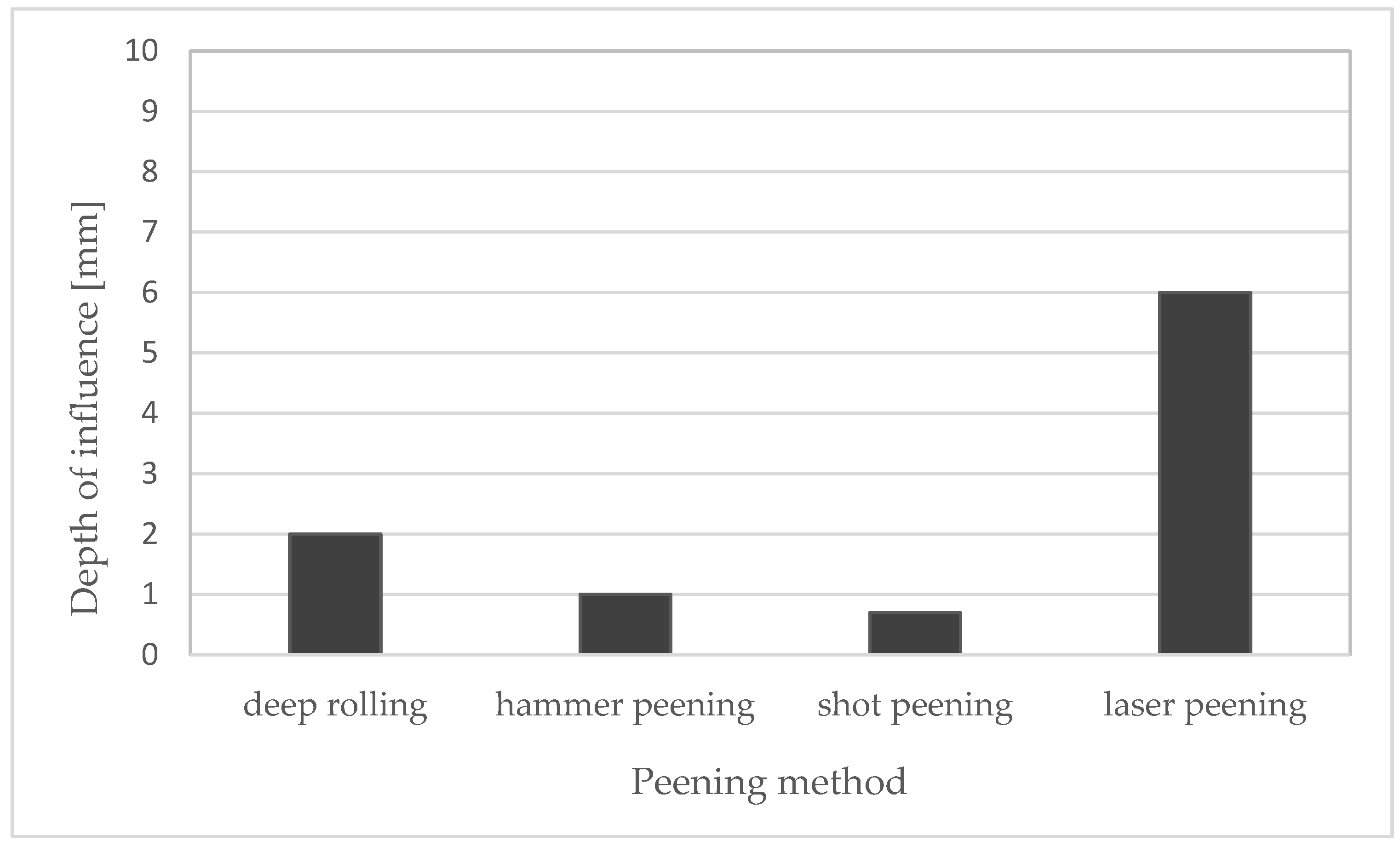
Figure 3. Depth of influence of deep rolling, and hammer peening, shot peening and laser shock peening—comparison. Compiled on the basis of [34].
3.2. Ultrasonic Nanocrystal Surface Modification
In 2000, a new pressing technique called ultrasonic nanocrystalline surface modification (UNSM) was patented by Pyoun due to the ease of creating a nanocrystalline structure [34]. UNSM is a method of material modification that involves peening the surface using movements of a tool that oscillates at a very high frequency. In a typical UNSM process, a tungsten carbide (WC) tip or Si3N4 ball is attached to an ultrasonic horn that strikes the surface up to 20,000 times per second at 1000 to 10,000 shots per square millimetres. To prevent the overheating of the shot peened workpiece, oil is used and sprayed on the workpiece [35][36].
The UNSM method has some advantages over other shot peening methods. The main advantage of this method is the possibility of extensive control of the process, i.e., applying a higher or lower static load, and changing the speed of oscillation by changing the amplitude of vibrations. Thus, this method allows high repeatability and the selection of ideal parameters for specific conditions. The method allows for grain fragmentation, introducing residual compressive stresses, reducing surface defects, and increasing hardness [37].
The UNSM method can be used to treat components after additive manufacturing, as demonstrated by Min Seob Kim et al. They investigated the behaviour of 316 L steel after direct energy deposition (DED) fabrication, after optimising the process, improving the roughness corrugation, and increasing the microhardness by 72%, 80%, and up to 71.2%, respectively [38]. Studies have also been conducted for titanium and its alloys [39], aluminium alloys after 3D printing [40], as well as 304 steel [41] or chromium-molybdenum steel [42].
3.3. Laser Shock Peening
The laser shock peening technology was developed at the Battelle Institute, dating back to the late 1960s. The laser shot peening (LSP) method uses pulses of laser light to generate shock waves that are expected to deform the material and leave residual compressive stress [28]. Laser light and a transparent layer are required, although a non-transparent layer is also often used. The temperature at the heating point reaches up to 10,000 °C and the pulse length is about 0.15 to 0.30 ns. LSP can be performed in two configurations, direct and limited ablation. A transparent layer (usually water) is used to reduce the plasma produced on the surface and increase the shock wave’s intensity. After the laser light beam passes through the transparent layer, it hits an opaque layer, usually made of aluminium, zinc, or copper, which is also called a sacrificial coating. The opaque layer is used to prevent direct laser ablation on the surface and melting [43]. An impulse of laser light reaches the absorption layer and then ionisation occurs in the heated zone, and a shock wave is generated, which plastically deforms the material [44]. The resulting compresive residual stresses (CRS) can reach up to 1.5 mm below the surface, depending on the method used [45]. Figure 4 shows different surface severe plastic deformation (SPD) treatments and the corresponding plastically deformed top surface of the target material.
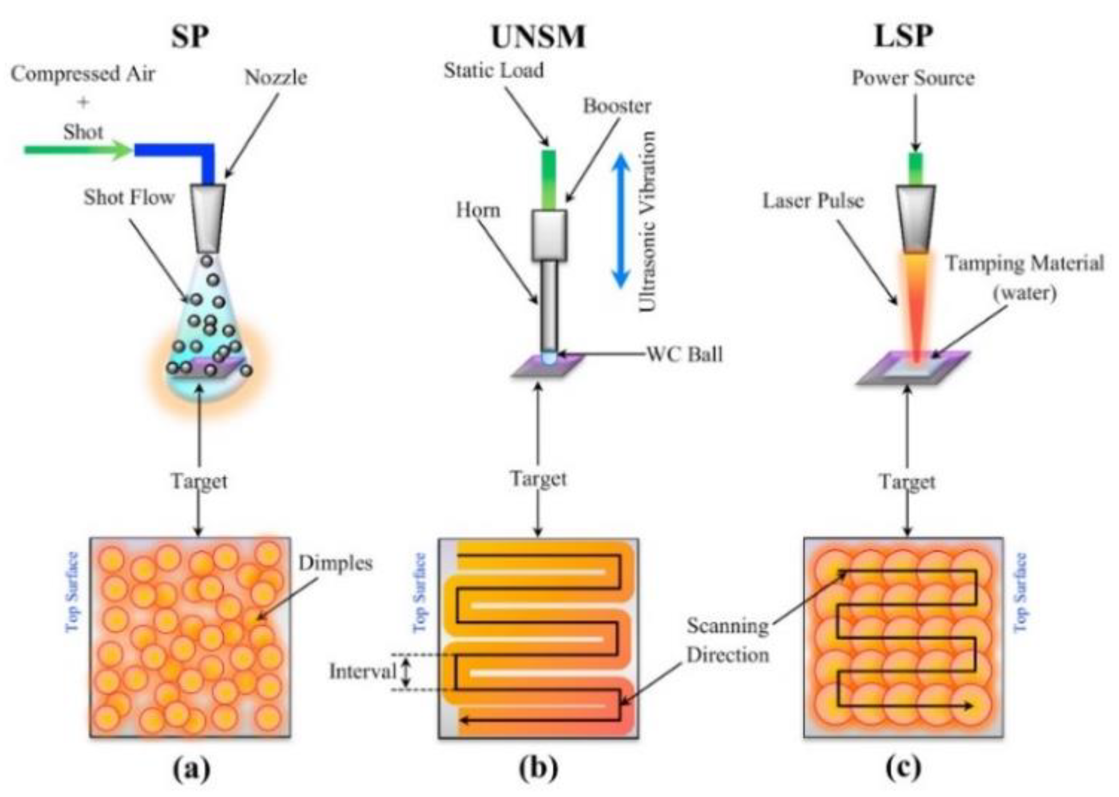
Figure 4. Schematic illustration of different surface SPD treatments and the corresponding plastically de-formed top surface of the target material: (a) SP, (b) UNSM, and (c) LSP processes (reproduced with permission from Ref. [46], Copyright 2021, Elsevier).
3.4. Flap Peening
In this method, balls are placed on two or more flaps which are fixed on a shaft. The tool is then made to rotate, which transfers energy to the balls, and the tool is brought close to the surface so that the balls begin to strike the material, thus deforming it, leaving numerous indentations [47].
3.5. Micro Shot Peening
Micro shot peening is carried out using minimal spherical particles called fine-particle or micro shot. The main difference from the SP is the sizes of shots that range from 0.03 to 0.15 mm in diameter. Generally, the micro shots are made of high-speed tool steel, cemented carbide, glassy alloy and ceramic, with high hardness [48].
It has been found that micro shot peening improves the scuffing resistance of 17CrNiM steel, and a combination of SP and micro shot peening gives even better results [49]. Other studies indicate better roughness, hardness, and CRS parameters compared to SP, and the combined treatment of SP and micro shot peening also improved all of these values compared to SP [50]. An improvement in fatigue strength for railway axle steels of 25% compared to the unpenned surface has also been observed [51]. Research is also being conducted on titanium alloys regarding the influence of shot size on material properties and corrosion resistance after the peening process [52].
3.6. Water Jet Peening
In this method, the pressing medium is high-velocity water droplets hitting the surface. The droplets generate a high peak pressure which plastically deforms the surface. Water jet peening is a term used in many other peening methods, but it should be noted that it is different from cavitation peening. Therefore, in order to avoid misunderstandings, the classification used by H. Soyama was adopted. Water jet peening refers to methods using water jets, where water droplets are the pressing medium, and the mechanism is the collision of liquids. On the other hand, cavitation peening is a method using cavitation impacts, and the material deformation mechanism is due to shock waves. The problem of dividing these methods is probably due to the fact that, in classical cavitation peening, cavitation is induced by a jet of water injected at high speed into the water [53][54]. Results on spring steel, titanium, and nickel suggest that this may be a valuable method for applications where increased roughness and CRS are required [55].
3.7. Oil Jet Peening
The principle of this method is the same as for water jet peening, the difference being the medium, which is hydraulic oil, used to create the jet. With this method, it is possible to introduce CRS without significant changes in the surface topography. The maximum surface CRS value after oil jet peening can be 80–85% of the yield point, while for shot peening, it is 45–97%. For shot peening, the surface CRS is 30–80%, for water jet peening, it is 30–60%, and for cavitation water jet peening, it is about 89% of the yield strength [27][56][57]. By using oil jet peening, it is possible to improve CRS in materials such as low carbon steel or aluminium alloys.
3.8. Ultrasonic Shot Peening
This method uses powerful ultrasonic vibrations of a hard body with a high frequency, usually ultrasonic, which set spherical shots in motion. As a result, the intensity of pressing is very high. The main difference lies in the absence of the medium setting the shots in motion (in the form of air or steam). There are also shot collisions, so there is no uniform angle of incidence on the component as in the case of SP, where the angle is 90°, and there is no ball impact force [58]. Studies comparing ultrasonic shot peening (USP) and SP suggest two approaches that can be considered. Tekada found similar structural and mechanical properties for USP and SP, but concluded that under similar conditions, a larger volume of nanocrystallites was observed after SP. However, a different conclusion was reached by Dai and Shaw, who stated that, because the shot size used during USP can be larger than for SP, the unit impact is able to deliver more energy, despite the lower particle velocity [59]. According to Tekada, the coverage area in his condition was 170%/s and the particle velocity was >100 m/s for SP. For USP, the coverage area was 20%/s and the particle velocity < 20 m/s with a very large velocity distribution in contrast to USP. Despite many attempts, it has not been possible to provide a consistent model for multiple impacts [60]. Research in this area suggests that the type and composition of the peening balls, among other things, influence the intensity, but to a lesser extent than the length of peening time. USP gives good results for soft materials and reduces the probability of crack initiation and propagation. Positive aspects have also been found for the physical and mechanical properties of such treatment, such as improved corrosion resistance, increased contact, and fatigue strength [61].
4. Cavitation Peening
Cavitation peening does not use shots but produces cavitation, and the deformation is caused by pressure waves and microflows from collapsing bubbles and cavitation clouds [53]. As in the case of water jet peening, this method does not leave any contamination in the material in the form of shot particles, and the process can be controlled [62]. A great advantage of cavitation peening is the absence of a shot peening medium that could contaminate the surface, as in other methods, e.g., SP, where ceramic or metallic particles are used, or, as in the case of LSP, where surface contaminating products may appear. Differences between cavitation peening and water jet peening (WJP) also include the relationship between injection pressure and process capability. In the case of WJP in the range from 20 to 60 MPa, the process capability also increases with increasing pressure. The situation is different in the case of CP, where this relation has a parabolic shape in the same range, i.e., it increases to a value slightly below 40 MPa, and then decreases. The process efficiency at 40 MPa is three times higher for cavitation peening than for water jet peening [53]. This method is effective for peening hard materials such as titanium and its alloys [63][64]. Chromium-molybdenum steel is also a topic for research due to its common use in industrial applications [65][66][67].
4.1. Cavitation
The name cavitation—used in physics and technology—is derived from the Latin word ‘cavitas’ (emptiness, cavity). Cavitation is a rapid physical transition from a liquid to a gaseous state due to a decrease in pressure, which is associated with the appearance in the liquid of the so-called cavitation bubbles with huge implosion loads [68][69][70]. Bubbles filled with steam, dissolved gases or both steam and gases are formed in places with a pressure reduced to a critical value and implode in places with increased pressure. The time of collapse of the bubbles may be below 0.001 s.
The gas contained in the cavitation bubble causes the bubble to be reconstituted after implosion, and this process can repeat several times [71][72]. The determining factor for the formation of cavitation is the changing pressure field. There must be a region in the flow where the pressure drops to a value close to the saturated vapour pressure and then rises. The factors influencing the formation of cavitation are pressure, temperature and velocity of the fluid flow. Other factors that facilitate the cavitation phenomenon include the surface shape with which the liquid contacts the presence of impurities and gases dissolved in the liquid [73].
Osborn Raynolds first described the phenomenon of cavitation in 1894. It can be observed in liquids with a non-uniform velocity distribution. If the fluid rapidly increases its velocity, the static pressure of the fluid decreases. The boiling point of a fluid is closely related to the pressure surrounding the fluid. As the pressure decreases, the boiling point also decreases. If the fluid’s static pressure drops low enough, the fluid starts to boil and thus, cavitation bubbles form [74][75]. Figure 5 shows the collapse of a cavitation bubble, i.e., cyclic changes in bubble size with wave propagation in the liquid, followed by an implosion, i.e., a sudden reduction in bubble size leading to its disappearance. Implosion causes vapour to condense inside the bubble, and the implosion pressure ranges from several hundreds to several thousands of mega Pascals. Important for understanding the mechanism of material deformation during cavitation is the formation of microbubbles. If the collapsing bubble is in contact with the solid surface, the diameter of the microstructure can be approximately 10% of the bubble radius, and its velocity will be high enough to deform the solid surface [29]. If the asymmetric collapse of the bubble is at larger distances from the solid surface, there will be a significant reduction in its failure [76][77][78].
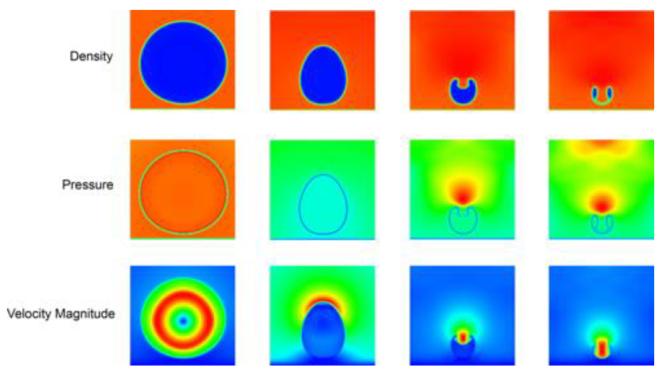
Figure 5. Sequences of collapse process of a H2O vapour bubble near a solid wall (from left to right), shown by density, pressure, and velocity magnitude fields (reproduced with permission from Ref. [79], Copyright 2020, American Physical Society).
The formation of liquid microbubbles may also be due to the fact that the pulsating cavitation cloud interacts with spherically shaped bubbles close to the solid. These interactions cause the bubbles to oscillate, and their shape becomes unstable. If the amplitude of the bubble oscillation is large enough, microstructure formation begins to occur as the liquid surrounding the bubble begins to flow through the bubble towards the solid. The velocity of the micro-streams can range from 156 to 175 m/s, according to various sources [80][81]. Gibson has shown that jet formation, direction, and intensity are functions of the bubble–bubble interaction [82].
As a result of the interaction of bubbles in the cloud, the cloud collapse process experiences a slight deceleration in the primary phase and significant acceleration in the final phase of implosion. This results in the generation of a much higher final pulse pressure than is apparent from the analysis of the implosion of a single bubble [83][84]. The velocity of the micro stream produced by the interaction with pressure pulses resulting from the collapse of other bubbles and the propagation of the shock wave can be as high as 400 m/s [85].
Many types of cavitation can be considered, and successive authors have proposed their own divisions of this phenomenon. The most popular and, at the same time, the simplest division is the one proposed, among others, by Lauterborn [78]. Considering the causes of cavitation, researchers can distinguish the following types of this phenomenon [86]:
-
optical cavitation;
-
molecular cavitation;
-
acoustic cavitation;
-
hydrodynamic cavitation.
4.1.1. Hydrodynamic Cavitation
Cavitation can be induced in many ways; however, hydrodynamic cavitation seems to be the most common type used for cavitation peening treatment [73]. Hydrodynamic cavitation can occur in the Venturi tube, orifice, or nozzle components, as a result of local pressure drop caused by various constrictors or by the mechanical rotation of the vortex diode and other rotating-type devices [87]. As an example, when high-pressure water is injected into the water, it is produced in the core of the vortex in the shear layer around the jet where the pressure drops; in addition, the vortex cavitations combine to form a cavitation cloud consisting of smaller bubbles, i.e., cavities. As the cavitation cloud reaches the surface, it becomes a ring vortex cavitation. Hence, the cavitation vortex collapses, thus hitting the surface in part of the ring. There are two developments of this method, cavitation jet in water and cavitation jet in the air [53]. Overall, the hydrodynamic cavitation can appear in a flowing liquid due to a decrease and subsequent increase in the local pressure-generating cavitation field [73][88].
4.1.2. Acoustic Cavitation
Acoustic cavitation is called the growth and collapse of bubbles under the influence of an ultrasonic field [89]. Ultrasonic waves propagate in a liquid medium, causing mechanical vibrations of the liquid. Air bubbles contained in the liquid behave as specific cavitation nuclei, while areas of higher and lower particle density are created in the liquid [75][90]. As bubbles collapse, shock wave propagation and growth occur. This type of cavitation can occur under the influence of pressure field changes caused by oscillatory movements of the sonotrode excited by the transducer.
Apart from the benefits of cavitation action, it can cause material surface deterioration called cavitation erosion, resulting in erosive material loss. According to the authors’ previous papers, the erosion mechanisms for materials such as metals, plastics, and ceramics differ [91][92][93]. In the case of metallic materials, surface roughening resulting from plastic deformation and phase transformations usually precedes the fatigue-induced detachment of eroded material [94][95][96]. The test rigs employed for cavitation erosion testing primarily utilise hydrodynamic and vibratory cavitation. Vibratory cavitation erosion resistance tests are mainly conducted under ASTM G32 standard recommendations [97][98][99], while hydrodynamic cavitation test rigs usually conform to ASTM G134 standard (cavitating liquid jet) or are not-standard solutions, such as rotation discs or cavitation tunnel rigs [100][101][102]. Therefore, optimising the cavitation peening process parameters is necessary to prevent the surface from the erosive action of cavitation and obtain the required peening effects.
This entry is adapted from the peer-reviewed paper 10.3390/ma15072476
This entry is offline, you can click here to edit this entry!