Your browser does not fully support modern features. Please upgrade for a smoother experience.
Please note this is an old version of this entry, which may differ significantly from the current revision.
Subjects:
Energy & Fuels
Creating climate-adaptive energy-efficient structures is also facilitated by using innovative materials, such as phase-change materials (PCM). The energy-saving potential was considered using the example of a three-story office building in China. It was modeled under different climatic conditions. The energy-saving potential of Shenyang, located in a harsh cold climate, was the most sustainable.
- natural convection
- heat transfer
- energy efficiency
1. The Trombe Wall
The depletion of natural resources has sparked interest in renewable energy sources, such as solar energy. Its consideration and application are possible even in undeveloped, remote areas. According to the data given in [43,44], passive solar technology can reduce the annual heating requirement by up to 25%. In order to store solar energy and reduce pollution and greenhouse gas emissions, a construction called the Trombe wall is beginning to be actively used in architecture and construction.
The classic Trombe wall consists of a basic 10–40 cm thick wall (brickwork, concrete, stone), preceded by single or double glazing. The glass surface is set back 2–5 cm from the main masonry, forming an air chamber. For moderate climates, single glazing is sufficient, and for cold climates, double glazing with Low-E must be used [45]. For harsh climates, according to [46,47], the width of the air duct must be significantly larger (29–35 cm).
The Trombe wall is constructed so that it faces south. The core masonry is covered with a dark heat-absorbing material on the outside, which is generally selective and has a high absorption capacity and low emissivity [48,49,50,51]. The idea behind the Trombe wall design is that heat from sunlight passes through the glass, is absorbed by the dark surface, accumulates in the wall, and slowly passes inside the building through the masonry, heating the indoor air through radiative and convective heat transfer. Ventilation holes in the upper and lower parts of the solid wall provide the necessary air circulation [46,52,53].
The wall design originated from the American engineer Edward Morse, who designed it for the first time in 1881. In 1960, the French designer Felix Trombe used the results of Morse’s research, revived the idea, and improved its design and functionality. Since then, the dark glazed wall became known as the “The Trombe wall” [44,54].
The exterior glazing of the Trombe wall is fitted with adjustable dampers and adjustable ventilation openings. In this way, the Trombe wall can be modified and adapted to different climates, purposes, and seasons, as shown in Figure 1 [34].
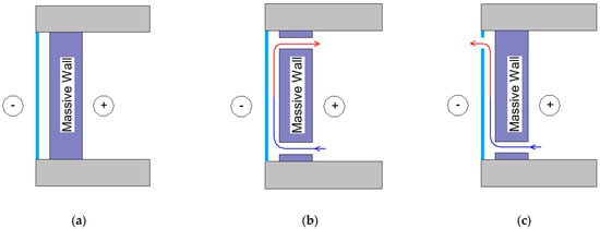
Figure 1. Trombe’s wall modes: (a) winter night; (b) winter day; and, (c) summer day (data from ref. [34]).
In winter, it is recommended to keep all dampers and vents closed at night, i.e., use the unventilated mode (Figure 1a). In this way, a layer of air insulation is formed, which retains the heat accumulated during the day.
For winter day mode (Figure 1b), keeping the shutters closed while both vents remain open is recommended to allow air circulation between the room’s interior and the air duct through convection. Air from the room, entering the duct through the lower opening, is heated and returned to the room through the upper slot. If fresh air needs to be admitted, one of the flaps can be opened to allow outside air to enter the duct. The fresh air and room air mixture are heated together and transported through the top vent to the room.
It is advisable to keep the top opening and bottom flap closed during the warm season and the bottom opening and top flap open (Figure 1c). Due to the draught, room air flows from the lower vent to the duct; after heating, the airflow rises and then is discharged into the environment through the upper damper. In this way, excess warm air is drawn in, resulting in a summer cooling effect in the room concerned.
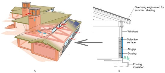
Architects and thermal engineers can design Trombe walls as a system of windows, eaves, and other building design elements to balance solar heat accumulation. For example, an intelligent selection of roof overhangs can help shade the wall and prevent heat build-up at times when heat is not needed.
The Trombe wall design is already used at the Zion National Park Visitor Center in Utah, The United States of America (climate zone according to Köppen is Dsb, Dsc), (Figure 2a). The 1.8 m high wall (total area 68.7 m2) runs the entire length of the south wall below a row of windows and accounts for 44% of the whole south side area. The core masonry is concrete blocks (20 cm) filled with cement mortar and coated with dark paint on the south side. In front of the wall is solid patterned glass and partially conceals the dark color of the wall without compromising transparency due to its good transmittance (Figure 2b) [55,56].
The performance of the Trombe wall is impaired if it is cluttered with furniture on the room side. According to the kitchen furniture’s location, the potential heat generated by the Trombe wall is reduced by more than 40%, as stated by [55].
The energy performance of the Visitor Center building was monitored over two years. The analysis consisted of measuring electrical values, making temperature profiles of the Trombe wall, and creating thermographic images. Figure 3 [55] shows the thermal distribution along the Trombe wall in December. The internal surface temperature is relatively uniform and ranges from 32 to 36 °C (90–96 °F). The maximum temperature is usually reached between 8 p.m. and 9 p.m. The lower temperature of the structure on the far right side of the Trombe wall is due to the shading of this part in the afternoon from the outside [55].
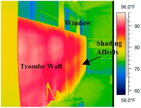
Figure 3. Thermal distribution of the Trombe wall in December (data from ref. [55]).
The calculations showed that during a heating period of 151 days, the Trombe wall operated for 149 days. It created an additional load on the heating system for two days, i.e., consumed heat energy. Overall, this structure stored heat and contributed to about 20% of the total heating of the building, i.e., it proved to be energy efficient [55,56].
1.1. The Trombe Wall with Nanomaterials
The efficiency of the Trombe wall can be significantly improved by replacing conventional glazing with lightweight polycarbonate panels filled with aerogel nanoporous insulation [56,57,58]. This nano-insulator is translucent. Aerogel has excellent thermal insulation properties because its closed nano-cells contain trapped still air [3].
The aerogel construction was investigated for the first time. There was no established methodology or design guide for determining the rational dimensions of Trombe walls containing aerogel insulation. The authors carried out Parametric modeling to fill this gap in science. During a full-scale seven-day test, peak temperatures of up to 45 °C were observed at the inlet of the duct. Thus, the fresh air inlet of the dwelling was preheated to 30 °C, which provided an internal temperature of 21–22 °C without additional heating. The monitoring results were confirmed with up to 5% of the predictions.
1.2. The Trombe Wall Using Phase-Change Materials (PCM)
One component of the Trombe wall, solid masonry made of brick or concrete, can be replaced by a phase-change material (PCM) [60,61,62,63,64,65]. Phase-change materials refer to materials that store and release heat energy during melting and freezing (change from one phase to another). When such a material freezes, it releases much power in latent heat or crystallization energy. Conversely, the same amount of energy is absorbed from the environment [44,66]. The classification of phase-change materials and the frequency of their use in different world regions is given in Figure 4a,b [67].
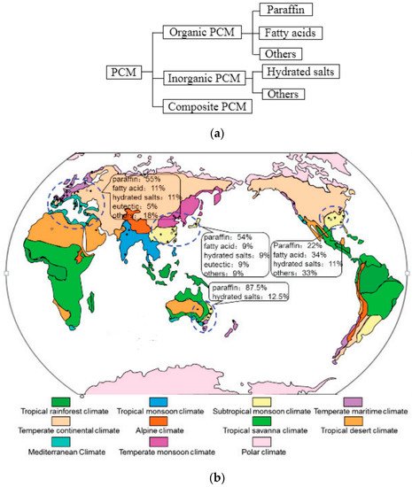
Figure 4. The classification and the use frequency of different phase changing materials types in various regions worldwide: (a) classification; (b) use frequency (data from ref. [67]).
One of the first PCM uses for building structures was considered by L. Bourdeau [68]. Conducting a numerical study, he observed that a 0.15 m thick wall made of concrete could be replaced by a 0.035 m thick wall made of phase-change material (calcium chloride hexahydrate CaCl2∙6H2O) and work similarly. Works [69,70] are based on his conclusions.
A team of Japanese researchers led by Onishi [72] conducted a similar study of the heat fluxes of the Trombe wall using a phase-change material. The simulation results indicate the effectiveness of PCM and suggest the possibility of further development of homes using this design for potential low energy consumption. The researchers recommended several further systematic tests to optimize PCM integration walls (detailed investigation of the phase-change point, the proportion of PCM in walls for heat storage and their size, etc.).
1.3. The Trombe–Michel Wall
The Trombe composite wall, also known as the Trombe–Michel wall [23,31,34,44,58,59,60,61,74,75,76], is a complex construction of the following components: a transparent glass plane, a solid wall, a closed cavity, a ventilated air cavity, and an insulating panel (Figure 5).
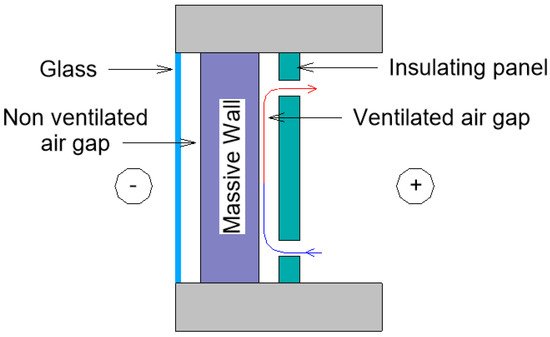
Figure 5. The Trombe–Michel wall (data from ref. [34]).
The glass surface lets in incident sunlight, the solid masonry wall receives and absorbs some of the sun’s energy, heating it. A kind of greenhouse effect is created in the closed cavity. The masonry wall transfers part of the absorbed energy to the ventilated duct of the building, and then it enters the room through convection. The heat in the room can be controlled by influencing the airflow in the duct through the ventilation openings. The thermal resistance of the wall is higher than that of a classic Trombe wall due to thermal insulation and a closed air cavity.
The Trombe composite wall with phase-change materials’ combined behavior (Figure 6) is given in [70]. Instead of classic solid masonry made of brick or concrete, they used “bricks” made of phase-change materials. The PCMs were packaged in a polyolefin shell in a parallelepiped shape (21 cm × 14 cm × 2.5 cm). A mixture of hydrated salts water + calcium chloride (CaCl2) + potassium chlorides (KCl) + additives) was used as the PCM. The wall consisted of nine bricks arranged 3 × 3 in a wooden frame. There were black-coated metal plates on the outside used as absorbent plates.
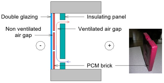
Figure 6. The Trombe composite wall with PCM (data from ref. [70]).
The heat fluxes and temperatures on the inside and outside of the wall made of phase-change material were considered. During the period considered, the maximum temperature of the wall reached 55 °C on its outer surface and 52 °C on the inner side. At sunset, the heat flux had a negative value on the outer side, while on the other side of the wall, it was always positive and varied from 0 to 50 W/m2.
The flow rates in the lower and upper vents and inside the ventilation duct were measured. The difference between the flow velocities in the vents increased as the solar flux increased, i.e., by midday. The velocity in the vented duct is close to the value of the velocity in the lower vent. It is also important to note that free convection is predominant, as air velocities are below 25 cm/s.
In [46], the problems associated with using the Trombe–Michel wall were also described, namely the possibility of condensation at significant temperature differences in harsh climatic conditions. If the thermal insulation layer’s proper vapor barrier and waterproofing are neglected, mold may appear on the thermal insulation layer. Depending on the climatic conditions, the thicknesses of the Trombe wall components can vary considerably [79]. If the wall thickness increases, the usable floor area may decrease, and the construction may become more expensive. At the same time, the amount of sunlight during the day to illuminate the room may also decrease. When erecting the Trombe–Michel wall, it is essential to consider that it may be difficult to clean dust and dirt from the space between the glazing and the wall during operation, as it is enclosed.
1.4. The Trombe Wall with Photovoltaic Cells
The combination of solar panels and the Trombe wall attracts attention as this combination effectively improves thermal comfort and generates electricity.
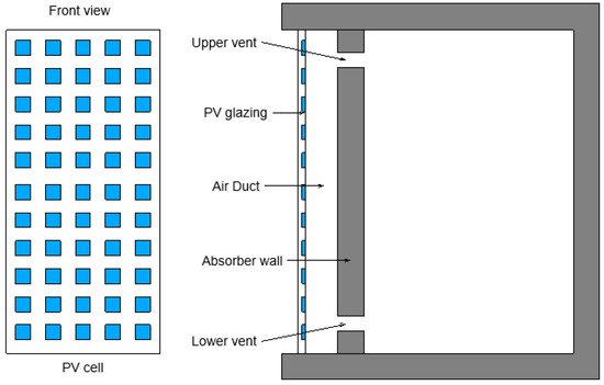
The use of the Trombe wall may be limited due to the dark surface absorbing light due to high aesthetic requirements for buildings. This problem can be solved using photovoltaic cells with a dark blue tint. A schematic representation of the Trombe wall with photocells is shown in Figure 7 [80,81].
It is important to note that all studies presented above do not involve high-rise construction. A detailed analysis of the Trombe wall design has not been carried out for high-rise buildings. However, they undoubtedly have an excellent potential for solar energy storage due to their substantial glass façades. A comparative analysis of the thermal performance of buildings with different modifications of the Trombe wall, e.g., with a single air gap across the entire façade height and with air gaps for each story, should be carried out.
2. Double-Skin Façade (DSF)
Since the early 2000s, the number of buildings with translucent façades has increased significantly. Glass is taking up more and more space in the wall envelope, and in some cases, the entire façade is made of glass. Without any doubt, this gives the building a very particular aesthetic appeal [89,90,91,92]. Glass surfaces accentuate sharp edges and regular curves, making the overall appearance of the building more expressive, tidier, and modern. The growing interest in “glass buildings” would not have been possible if intensive technological advances had not followed. The invention of electrochromic glass with variable transparency, low-emission energy-efficient glass, self-cleaning and water-repellent glass, fire-resistant glass [93], the emergence of aerogel, and innovative glazing systems (structural, semi-structural, modular, and spider glass) have given rise to the most extraordinary architectural ideas.
The development of science and technology and ongoing engineering research has created a qualitatively new type of glass façade—the double-skin glass façade. The design of a double façade consists of an external glass surface, an air-filled gap, and an internal glazing system (single or double glazing), sometimes combined with opaque walls [95,96,97,98,99]. The gap is ventilated by airflow caused by buoyancy (natural convection) or mechanical devices (forced ventilation). The distance between the glass planes can vary from a few centimeters to 2 m [100]. The heat transmitted to interior spaces is the sum of energies: energy directly transmitted through transparent surfaces from solar heating, secondary radiation from internal glass surfaces, and energy gains from ventilation air.
Nevertheless, glass façades provoke a certain degree of caution and concern among planners and builders. Designers consider the possible overheating in the summer and potential heat loss in the winter period of operation of buildings, which affects the comfort of living indoors and higher energy and utility costs [101,102].
Double façades can be modeled in various software systems, such as EnergyPlus, ESP-r, IES–VE, TRNSYS, IDA–ICE. A comparative analysis of these tools is presented in [103]. It was also found that the number of thermal zones into which the cavity is divided, the coefficient of convective heat transfer, the influence of wind pressure on the airflow in the gap, shading systems, and their position are among the most significant parameters in the modeling process.
There are two ways to create a climate-adaptive double-skin glass façade:
-
The selection of the optimum operation of the air duct. Analysis of the processes taking place in the air gap between the two façade circuits will result in a thoughtful design of the air gap, which will positively affect not only the aesthetic appearance of the building (no condensation on the surfaces) but will also result in savings in energy resources and utility costs.
-
The use of shading devices. Different shading devices can be considered if no rational air channeling solution can be identified after analyzing the various possibilities.
Regarding fire risk assessment, experimental studies have shown that the critical factor is the depth of the gap: wider gaps are safer [100]. It is also better that the façade is divided into compartments. For example, in [104], a school renovation project using a double-skin façade (DSF) system combined with a diffuse ceiling ventilation (DCV) system is presented. A transparent façade is erected in front of the traditional façade. This system is called I-DIFFER. It not only reduces the need for heating in winter but is also an extremely safe fire protection method. Each classroom has its double façade compartment, which prevents the spread of fire, smoke, and sound to neighboring rooms.
2.1. Classification of the Double-Skin Façade
The design of a double-skin glazed façade may have different modes of operation in terms of thermal engineering.
-
Globally, double façades can be classified into two large groups: naturally ventilated and pressurized façades.
In work [105], a comparative numerical analysis of the cooling energy performance of a building is presented based on dynamic simulation to calculate the percentage effect of forced ventilation during a period of one year. Four variations of façade designs were considered: a double-skin glazed façade with mechanical ventilation (DL-Case-1), a single-glazed façade with mechanical ventilation (SL-Case-1), a double-skin glazed façade with natural ventilation (DL-Case-2), and a single-glazed façade with natural ventilation (SL-Case-1). The outcomes that were obtained for the environmental conditions of Abu Dhabi (the United Arab Emirates, climate zone according to Köppen is Bwh), Venice (Italy, climate zone according to Köppen is Cfa) and Würzburg (Germany, climate zone according to Köppen is Cfb) are also valid for cities with similar climatic conditions. The energy demand during the cooling period and peak power estimates for these designs are shown in Figure 8.
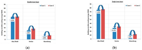
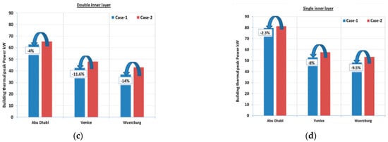
Figure 8. Seasonal energy consumption during the cooling period (a) building cooling energy for the case with DL, (b) building cooling energy for the case with SL, (c) building peak power for the case with DL, (d) building peak power for the case with SL (reprinted from [105]).
In Abu Dhabi’s climate, the building’s cooling energy requirement was reduced by 1.5% in Case 1 compared to Case 2 for double interior glazing and 1.9% for single interior glazing. A peak power reduction of 4% was achieved when switching from Option-1 to Option-2 using double glazing, and in the case of single glazing, the reduction was only 2.3%. For Venice, the transition from Option-1 to Option-2 is significant. Cooling energy required is 15% less and peak power is reduced by 11.6% in a double glazing design. For single internal glazing, the savings in cooling energy is 11.5% between the two types of ventilation, and the difference in peak power reaches 8%. Due to the lower ambient temperature in Würzburg compared to Venice, all figures also increased proportionally. The peak power reduction for the double-glazed façade reached 14%. The need for cooling has decreased by 22%. By comparison, single glazing reduces peak power by 9.5% and 17% in cooling [105].
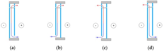
In mode A, room air circulates in the air duct, passing into the HVAC system. The air enters the duct through the lower opening on the inner façade, then it rises and passes into the HVAC. In mode B, fresh air enters the duct through the outdoor duct. In winter, fresh air can be preheated before entering the room. Types A and B are mechanically ventilated. DSF is easily integrated with the building’s HVAC system.
In mode C, the air heats up and rises naturally. Fresh air can be supplied to the room from the street with an open window on the inner façade. If all the windows on the inside of the façade are closed, then the outer wall becomes isolated from the inner space. In this way, the thermal impact on the building during hot periods can be reduced.
In mode D, the double-skin façade behaves like a solar chimney. The room air passes through the bottom vent into the duct. After passing the duct, the air goes directly to the environment. When installing an air intake, it is possible to realize natural ventilation of the room without air conditioning.
2.2. Shading Devices for Double-Skin Façades
Scientists pay particular attention to shading systems. Various shading solutions from blinds to “natural” blinds, where the double façade opening is planted [113,114,115,116,117], were proposed worldwide. Using computer modeling, Stec et al. [113] showed that placing vegetation inside the cavity of the double façade can provide a comfortable indoor microclimate. The researchers compared the thermal performance of two shading devices inside the double-skin glass façade: bio-shading and using louvers. The result showed that the green layer had a lower surface temperature (35 °C) than the louvers (55 °C). It is estimated that this leads to a reduction in the energy consumption of air conditioning systems by up to 20%.
G. Baldinelli [96] presented an analysis of a double-skin façade with integrated movable shading devices. Such a design was developed to overcome possible summer overheating. The model was created for a south-facing façade, taking into account the climatic data of central Italy (Cfa). The trajectory of the sun was taken into account using the ray-tracing method. The modeling was compared with data from a similar experimental installation (Figure 11).
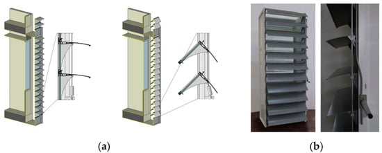
Figure 11. Movable shading devices: (a) model of the façade element in winter and summer; (b) experimental installation (data from ref. [96]).
The winter configuration of the proposed façade allows for a doubling of solar heat despite the shading systems. In summer, the solar heat is mainly absorbed by the outer glass layer. There is no significant impact on the inner glass surface and the interior environment, which reduces the cooling requirements of the building and saves on air conditioning. The performance of this type of façade was compared with traditional building envelopes, with single pane glass and opaque walls in an office building in central Italy. A year-long study showed that the proposed façade significantly improves the energy performance of the building.
A study [119] numerically investigated the thermal performance of a double façade using the hot climate conditions of Saudi Arabia (climate zone according to Köppen is Bwh). This study considered the effect of the cavity geometry, the size of the openings between the shading device lamellae on the airflow pattern, and air temperature distribution. To assess the influence of the studied variables on the double façade’s design, 13 calculation models, 12 of which had a shading device and one without a shading device, were built using computational fluid dynamics (Figure 12).
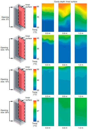
Figure 12. CFD modeling as studied (reprinted from [119]): vertical temperature distribution on the inner façade.
An important issue regarding the application of sun shading devices is the question of their positioning. Inside the gap, they are protected from the weather. Still, they alter the airflow in the duct and, if installed incorrectly or miscalculated, can negatively influence the entire system. On the other hand, external Venetian blinds are in direct contact with the outside air, wind, and rain, but they offer better protection from the incident solar heat. Researchers from Belgium [123] have considered this question in a multi-faceted way. They took into account factors such as the color of the shading devices; the position within the cavity—closer to the outer plane, closer to the inner plane, or in the middle; the presence or absence of ventilation openings. Placing light shading devices in the middle of the air cavity with ventilation openings can save up to 23.3% on space cooling during hot periods.
2.3. Photovoltaic Cells in Double-Skin Façades
The use of photovoltaic cells as movable lamellas for shading and the outer surface of a double-skin glass façade is considered by many researchers. An example of this use is the study carried out by the public library building in Mataro, Spain [126]. The outer surface of the façade contains 20 kWh multi-crystalline photovoltaic cells inside the transparent glass, giving a translucent appearance to the façade. The ventilated space is 140 mm thick, and the inner surface is made of glass.
The previously mentioned work [105] compared the effect of photovoltaic panels in a double-skin façade with forced ventilation (Case-1) and natural ventilation (Case-2), using cities in different climatic regions (Abu Dhabi, Venice, and Würzburg). A summary of the annual results of the integrated PV system in the three cities is shown in Figure 13a,b.
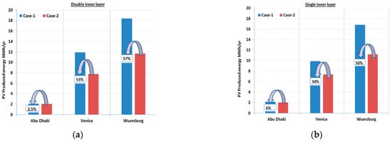
Figure 13. PV electrical produced energy assessment: (a) PV Yearly electrical produced energy—DL; (b) PV Yearly electrical produced energy—SL (reprinted from [105]).
Forced ventilation and photovoltaic cells increase annual energy production by 2.5% in Abu Dhabi for double-glazing and 6% for single-glazing. In Venice, annual photovoltaic electricity production reached 53% with double glazing and 34% with single glazing. A similar pattern of performance occurred in the city of Würzburg. The improvement was 57% with double glazing and 50% with single glazing.
The results [128] showed that the use of building-integrated photovoltaic cells as exterior solar shading devices produces on-site electricity and reduces cooling loads by 10% and 9.2%
Integrating photovoltaic cells with the building façade is considered energy-efficient if the photovoltaic cell does not overheat. High summer temperatures can increase the air temperature in the cavity of the double façade and reduce the overall energy efficiency of the photovoltaic cells. This process can result in a 0.4–0.5% loss of solar-to-electric conversion efficiency [112]. Work [127] is a numerical study of the thermal behavior of a mechanically ventilated double-skin façade integrated with a photovoltaic cell by cooling the air cavity with supplied cold fresh air. The DSF scheme used is shown in Figure 14. The type of air inlet, its location, and the deflection angles of the airflow are investigated.
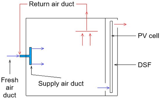
Figure 14. DSF scheme (data from ref. [127]).
2.4. Low-Emission Glass in Double-Skin Façades
Researchers suggest that the inner glass surface should be made of low-emissivity glass to prevent heat loss from the building [129]. The principle of low-emissivity glass is described in [130]. Any opaque object absorbs some solar energy and heats up when exposed to sunlight. At the same time, it emits energy in the form of infrared wavelengths. In summer, low-emissivity glass can let insufficient sunlight for illumination. Still, at the same time, it blocks infrared radiation produced by exterior roads and buildings due to the absorption of the sun. It significantly reduces the need for air conditioning in rooms. In winter, low-emission glass can also let in some visible solar energy. Still, at the same time, it reflects long-wave radiation from indoor heating equipment, human heat, and lighting fixtures. Such heat loss does not occur in winter. Consequently, low-emissivity glass can effectively maintain the temperature in a room.
According to [129], low-emissivity glass offers better natural ventilation at all angles of incidence of sunlight (10–80°) and solar radiation intensity (50–1000 W/m2) (by approximately 13%). The airflow rate is reduced at higher incidence angles. Incidence angles of less than 40° result in insignificant reductions in air velocity (<4% per 10°), whereas tips > 40° development in more drastic decreases (8% per 10°). Thus, a double-skin façade with low-emissivity glazing of the inner plane provides more natural ventilation at lower angles of incidence of sunlight. An optimum airflow rate can be obtained with a cavity gap of 0.15–0.3 m.
2.5. Double-Skin Façade with Innovative Materials
Phase-change materials (PCM) are promising materials. In the building industry, integrating PCM materials into various structural elements or heating, ventilation, and air conditioning (HVAC) components can increase the thermal capacity. In turn, it helps reduce indoor temperature fluctuations, thereby decreasing the heating and cooling loads [131].
Goia et al. [132,133,134] compared a conventional glazing unit (DGU_CG-double-skin glass Unit Clear Glass) with a glazing unit with PCM (DGU_PCM). The width of the cavity between the transparent panels is 15 mm. In the first case, it is filled with air. In the second, the cavity is filled with RT35 technical paraffin. Goia’s development was, in turn, based on [132]. Measurements were made using the TWINS-Testing Window Innovative System (Figure 15) [132,135].
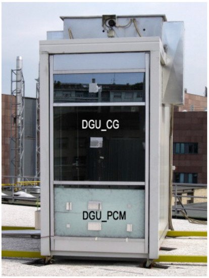
The measuring system consisted of 40 sensors. The sensor system measures the physical parameters of the double-glazed windows. Climatic conditions inside and weather conditions outside the chamber are also recorded by sensors. The tests were carried out for six months.
The change in the appearance of paraffin glazing during the day can be observed in Figure 16, which shows changes in the aggregate state, as well as changes in the transparency of paraffin in the façade during measurements from 10:00 to 19:00 [136]. Measurements were taken every hour. The results were obtained in summer during sunny weather. During this period, the layer of phase-change material completely melts and solidifies again. The dynamics of melting and solidification of the PCM layer are monitored by researchers by changing the transparency of the glazing. Until 13:00, PCM is in the solid phase. At this time, the PCM has a translucent appearance. At 14:00, it becomes clear from observations that most of the solid PCM floats in the volume of liquid PCM. At 16:00, the entire mass of PCM is in a liquid state. The studied PCM layer is completely transparent. Solidification of liquid PCM begins after 18:00. At 19:00, most of the PCM becomes solid and also translucent.
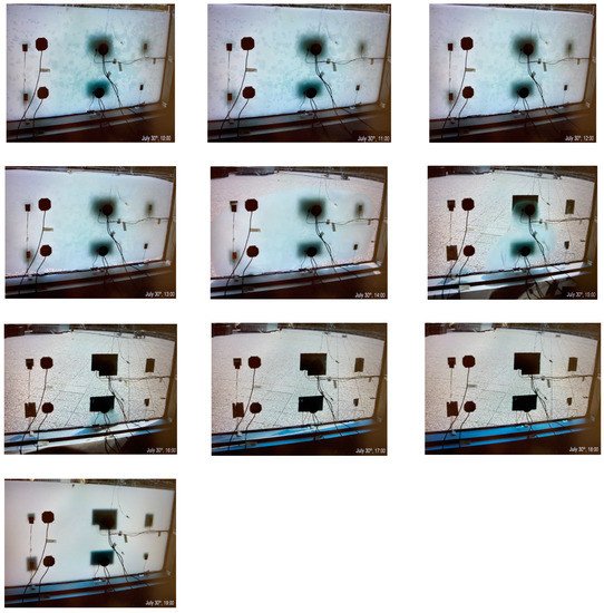
Figure 16. Changes in the aggregate state and transparency of wax in the façade (data from ref. [136]).
It was found that the thermal conditions of the indoor environment façade achieved using the DGU_PCM façade were significantly better than the DGU_CG façade for most of the time during the different seasons. In general, it was observed that the higher the level of solar radiation outside, the more benefits DGU_PCM offers. However, the careful optimization of the wax’s forward and reverse change temperature from the solid to the liquid state in glazing is still subject to study.
In combination with other solar energy conversion technologies, PCM is also efficient and feasible, e.g., in photovoltaic modules, they are used for temperature maintenance. Commercial PV cells can only convert solar radiation of around 14–20% into electrical energy [111]. The remaining solar radiation is converted into apparent heat, which causes the PV cell to heat up. Phase-change materials help to prevent the module from overheating. The numerical model results were confirmed by experimental data obtained from a test bench in Palermo, Italy [140].
The cavities were assumed to be ventilated with forced ventilation using the outside air exhaust method (Figure 17) [136].
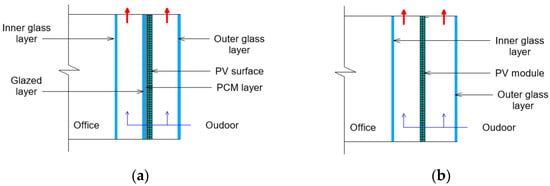
Figure 17. A scheme of glazed offices integrated with PV module (a) with PCM, (b) without PCM (data from ref. [136]).
According to the calculations made, the following conclusions can be drawn. Firstly, there is no need to integrate a phase-change material layer for photovoltaic panels during the heating season. From the moment cooling is required in the building, the demand for the innovative material increases. The cooling load is reduced by an average of 22%, irrespective of the climate. Secondly, with PCM, the average surface temperature of the photovoltaic module is reduced. Simulations using a simplified method of ventilation control show that it is possible to reduce the temperature of the PV module by up to 20 °C. It has a positive impact both on the thermal load of the building and on the efficiency of the conversion of electrical energy from photon energy.
2.6. Double-Skin Façade with an Inclined Plane
The article [144] considers the case when a double-skin façade has an inclined outer plane. If for aesthetic reasons, the architect decides to slope one of the walls, then this leads to significant changes in the design from the point of view of thermal engineering. As the wall slopes, the Nusselt number and the flow velocity decrease. The study was aimed at quantifying the wear and tear of the system using the French climate as an example. Changing the angle of inclination has a great influence on the heat transfer processes. At the angle of inclination α = 0°, the most intense heat transfer rate is observed. This is a classic case with an ordinary wall. Additionally, in the case of a non-inclined channel, the maximum mass flow occurs. This is also possible when the channel inclination angle is α = −2°. The researchers say the −10° angle is the optimal compromise between architectural considerations and heat and mass transfer. The inclined glass façade plane case can be observed at the Lakhta Centre building in St. Petersburg, Figure 18 [145].
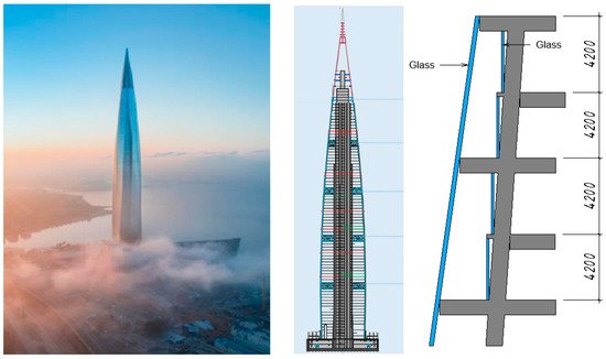
Figure 18. Lakhta Center (data from ref. [145]).
Another option of an inclined external glass surface in a double-skin façade implementation is to create a productive architectural surface system (PASS). A productive double-skin façade (PDSF) is its integral part (Figure 19) [146].
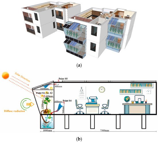
Figure 19. Productive double façade concept: (a) General view of the building; (b) Structural section (data from ref. [146]).
The design of the PDSF is an energy-saving indoor area, and it can co-generate solar electricity and heat and transmit daylight to the interior space.
PDSF is a space for comfortable growing plants, where light and shade meet plant growth’s functional requirements and habits. In such a tightly controlled environment, vegetable yields will be higher, and the most appropriate technology will shorten the growth cycle. Such systems can take advantage of aeroponics or aquaponics. All these benefits serve to create sustainable urban development [146].
This entry is adapted from the peer-reviewed paper 10.3390/buildings12030366
This entry is offline, you can click here to edit this entry!