Your browser does not fully support modern features. Please upgrade for a smoother experience.
Please note this is an old version of this entry, which may differ significantly from the current revision.
Subjects:
Engineering, Petroleum
Fluid catalytic cracking (FCC) is the workhorse of modern crude oil refinery. Its regenerator component plays a critical role in optimizing the overall profitability by efficiently restoring the catalyst activity and enhancing the heat balance in the riser reactor. Improvement in the device metallurgy and process operations have enabled industrial regenerators to operate at high temperatures with a better coke burning rate and longer operating cycle. Today, the carbon content of regenerated catalyst has drastically reduced to less than 0.1 wt.%.
- afterburn
- air/steam distributor
- catalyst regeneration
- FCCU
- maldistribution
- regenerator
1. Introduction
1.1. FCC Process and Its Importance in Petroleum Refineries
In an integrated refinery, the fluid catalytic cracking unit (FCCU) is the hub for primary conversion of low-quality and heavy hydrocarbon molecules to more valuable and lighter ones, which are essential components of transportation fuels (e.g., gasoline, jet fuel, and diesel). Since the first industrial application of fluid catalytic cracking (FCC) technology in 1942, the FCCU has mushroomed to become a pivotal component of the modern petroleum refining process [1].
Over the last six (6) decades, the FCCU has evolved significantly due to a better comprehension of the intrinsic process science and innovative engineering solutions [2][3]. The evidence of these is seen by the development of highly active and selective multi-spherical zeolite catalysts [4][5], and the improvement of risers for catalytic cracking [6][7][8][9]. These innovations have driven a major uptick in yields of different high-quality distillate fuels from poor-quality feedstocks, an increase in unit capacity and operating flexibility, and lower wastewater and emission generations, among others [10][11][12]. Nonetheless, the FCC process is very complicated; as shown in Figure 1, the unit is primarily made up of a reactor section and a regenerator section interlinked by transfer lines to provide for free transportation of spent and regenerated cracking catalysts between them.
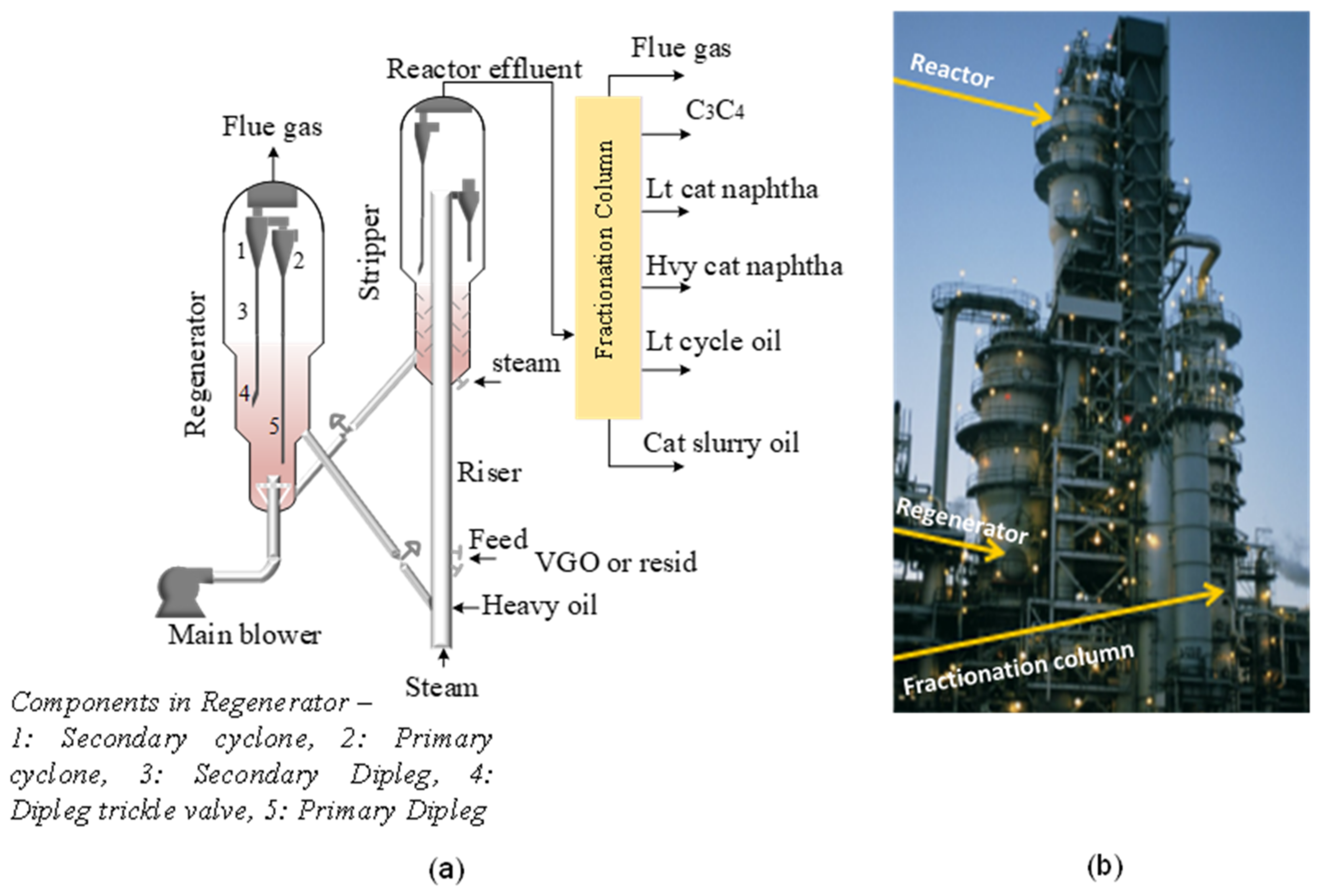
Figure 1. FCC unit. (a) Schematic diagram of a simplified set up; (b) industrial plant.
Five basic processes are involved in the FCC operation, including feed pretreatment, conversion, heat and pressure recovery, effluent separation, and product treatment [13]. The feedstocks (typically high-boiling-point petroleum fractions termed high-vacuum gas oil, HVGO, from the crude vacuum distillation unit) is preheated (149–400 °C) and charged into the riser inlet where it contacts hot regenerated catalysts stream en route from the regenerator, and the oil feed cracks as the mixture travels up the riser in a fluidized state into the reactor vessel where the effluent vapor is separated from the spent catalyst [14]. The cracked effluent vapor from the top outlet of the reactor is directed into the main fractionation unit for further treatment and recovery of high-value products while the residual slurry stream is sent back to the riser-reactor unit for recycling. As the feed cracks endothermically in the reactor section, a carbonaceous substance (i.e., coke) deposits on the catalyst, thereby resulting in its gradual deactivation and activity loss. Coked catalyst is drawn off the bottom of the reactor and transported by gravity to the regenerator, where the coke is combusted off in a fluidized state by injecting heat and air. The cleaned (regenerated) catalyst is then redirected back to the reactor section to continue the process loop [1].
Industrially, the catalyst travels at elevated velocities and completes the reactor and regenerator cycle in seconds. This is a precursor to surface erosion due to forceful solids impingements; hence, the internal surfaces of the riser, reactor and regenerator are equipped with an anchoring structure and thick internal refractory lining [15][16]. The exothermic coke combustion in the regenerator generates preponderance of heat, which produces the major thermal requirement for endothermic cracking reaction in the reactor/riser, necessitating a heat balance between the reactor and regenerator. The flue gas generated in the regenerator, which is rich in heat, is sent to the CO boiler and recovery gas compressor to regain some energy for other downstream applications before being emitted into the atmosphere together with catalyst fines. This makes FCC the highest polluter in the refinery [13].
1.2. Future Roles of FCC Process and the Importance of Process Intensification (PI) Technologies
In the future, FCCU must fulfill the following performance requirements to be both acceptable and profitable: high operation flexibility, minimal operating and maintenance cost, improved product selectivity, modularization, an increase in unit capacity and reliability, minimal energy consumption, and high compliance to stringent emission legislations. By implication, as depicted in Figure 2, FCCU must simultaneously accept more low-quality feedstocks (e.g., biomass) and produce high-quality fuels. With a decreasing trend in gasoline demand driven by electrification of the transportation sector, a switch to ultra-low sulfur diesel (ULSD) production will offer the maximum bottom upgrading advantage. The gasoline generated must be free of sulfur and nitrogen-based pollution gases (SO2, SO3, COS, H2S, N2, NO, N2O, NO2, NH3 and HCN). More so, flue CO emission will be eliminated and the CO2 generated will be upgraded for an economic incentive through the integration of carbon capture and utilization (CCU) technologies. On the flipside, to avoid supply and profitability downturn, FCCU will transition to maximum production of intermediate distillate petroleum fractions, especially the olefin product slates with longer turnaround periods. It will also accommodate the coprocessing of different types of biomass in its existing units with no compromise on device reliability and environmental requirements. Due to the energy market flipping, the FCC modular unit will equally be needed for a clean, safe, and modular supply of FCC products. These will attract the penalties of the alteration of combustion kinetics, cracking reaction and structural modification of the unit. A tradeoff for a more sophisticated design and operation than the present technologies may occur but will increase the investment cost. It is also worth stating that the current Houdry FCC process is highly arduous from lab, industrial and computational simulation standpoints, so a more sophisticated system will be an additional and unattractive burden.
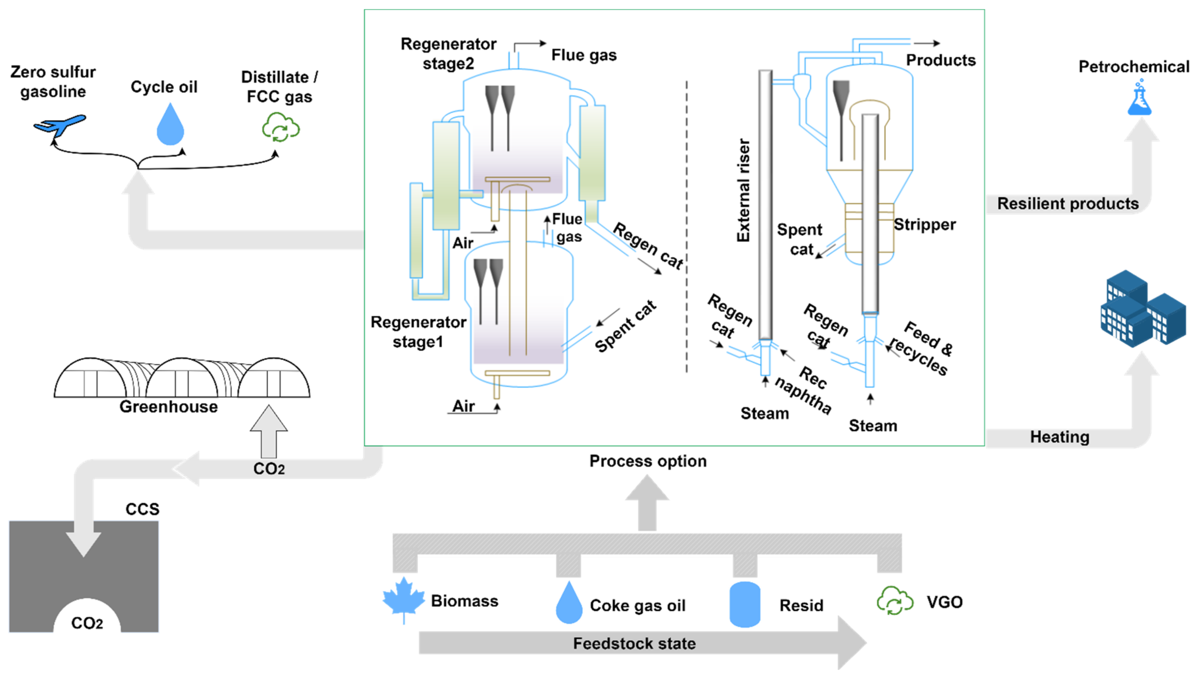
Figure 2. Illustration of future roles of FCC unit. Note: CCS: carbon capture and storage, VGO: vacuum gas oil, Rec: reactant (feed).
1.3. FCC Regenerator: Functions and Various Designs in Petroleum Refineries
The core functions of FCC regenerators are basically: catalyst activity restoration by eliminating the coke that builds up on the spent catalyst in the reactor without destroying the catalyst, providing heat balance for cracking reactions in the reactor and supplying hot fluidized regenerated catalysts to the feed nozzles [17][18]. The real distinctive processes and reaction mechanisms to achieve them under steady-state conditions are much more complex.
FCC regenerators are available industrially in different designs which are principally delineated by operating condition (bubbling, turbulent or fast fluidization), gas–solid contacting pattern (co-current or countercurrent), combustion level (partial or complete/fullburn), etc. Regardless of the design, commercial FCC regenerators are composed of common rugged structural devices, which are mainly:
-
Standpipes/slide valves: For building a hydraulic head by maintaining a column of fluidized particles. Spent catalyst standpipe transports coked cracking catalysts into the regenerator from the riser, while the regenerated catalyst standpipe allows the return of cleaned catalyst back into the reactor [19]. The embedded discrete slide valve controls the catalyst circulation rate (see Figure 1 and Figure 2).
-
Air/steam distributor: For even dispersion of feed gas into the regenerator bed cross section [22].
-
Cyclones: Usually in multiple pairs (primary and secondary) for separating entrained catalyst particles from flue gas and returning the solids back to the regenerator bed [13].
-
Plenum: A device positioned at the top of regenerator system, usually made of carbon steel for receiving flue gases from multiple pairs of cyclones before they are vented out. It also aids in minimizing catalyst loss [1].
-
Catalyst cooler: Auxiliary internal used to keep the unit temperature within the tolerance limit. It is one of the most flexible and reliable internals that functions optimally in the range of 100% design duty and can be safely shutdown or restarted during full operation [13].
-
Baffles: Auxiliary internal for inducing efficient gas–solid within the regenerator bed, among others [23].
2. Different Designs of FCC Regenerators
2.1. Full Regeneration Design
Regenerators are designed either as a single- or two-stage combustion regeneration systems (see Figure 3). This is one of the fastest-growing areas for regeneration intensification.
2.1.1. Single Stage Regenerators
In single-stage regenerators, the whole catalyst rejuvenation process takes place in one fluidized bed chamber [24]. Until the present, it has been the most commonly adopted mode due to the simplicity of the process and equipment design. Two process design approaches are widely explored in single-stage regenerators: complete combustion and partial combustion modes. A partial or incomplete burn allows mild countercurrent combustion (lower temperature between 620 and 675 °C and lean oxygen supply) of coke, generating a targeted large amount of CO which is further combusted to CO2 in a CO boiler (such as power for industry (PFI) boilers) or incinerator to reclaim energy in these gases [1]. Metals such as vanadium and nickel complexes are minimally oxidized and the coke hydrogen content is rapidly burned, with all deactivation precursors removed. Ideally, no O2 is present in its stack flue gas and temperature control is high but the coke on regenerated catalyst (CRC) is relatively high, usually about 0.1 wt.% or higher, which is typically the main performance indicator for regenerators. Flue gas emission is another serious issue in a partial burn regenerator; the efficiency of the boiler system is one important factor for meeting emission legislation. New advances for improving the boiler efficiency have evolved in the design of a CO boiler, resulting in enhanced CO burning and low supplementary fuel consumption; these include resizing the heat transfer surface and replacing the refractory furnace with a membrane water-walls furnace [14][25][26][27][28].
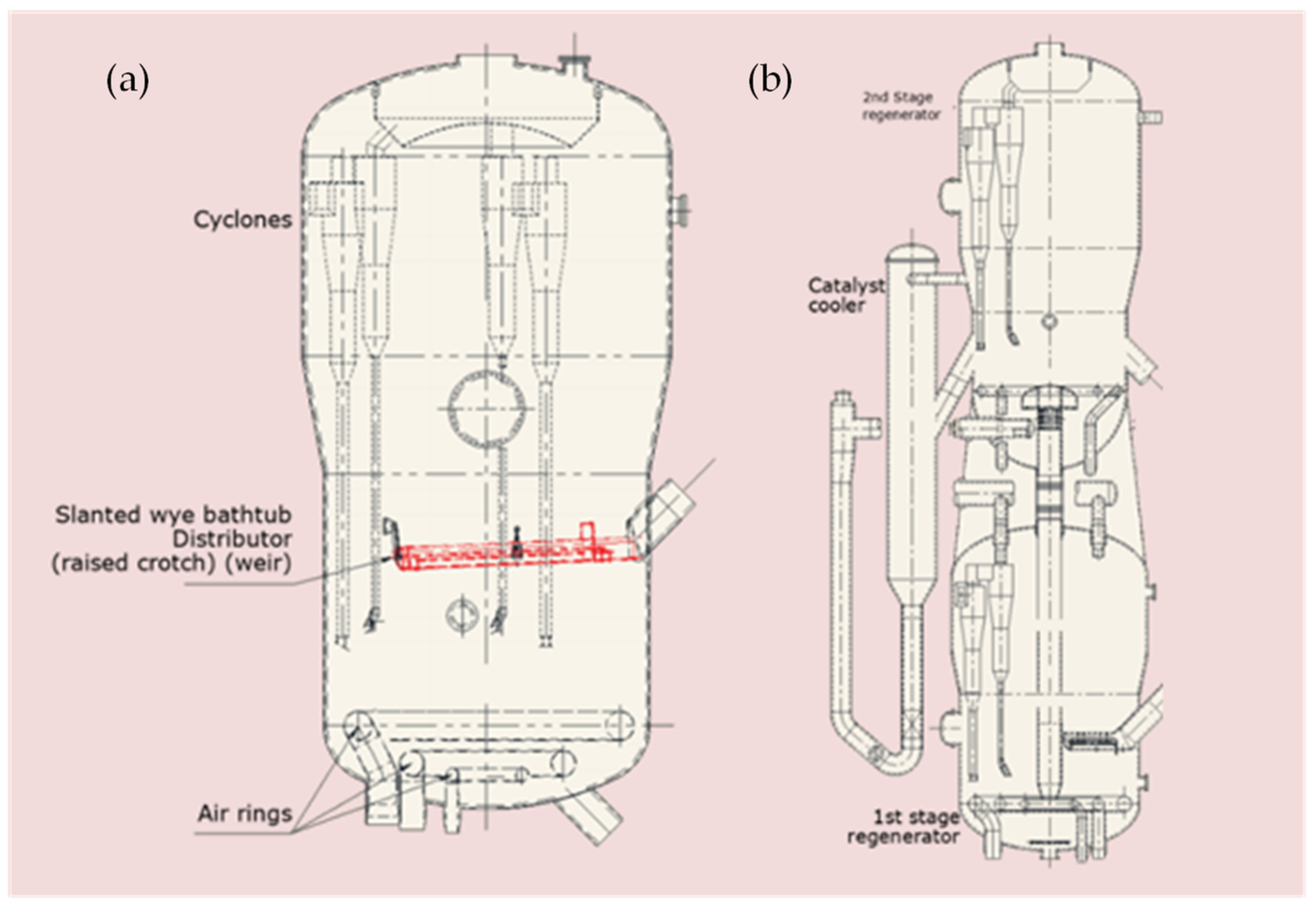
Figure 3. FCC regenerator full combustion designs: (a) single-stage regeneraator; (b) TechnipFMC two-stage regenerator (adapted from Singh and Gbordzoe [29]).
2.1.2. Two-Stage Full Burn Regenerator
In order to reduce the catalyst deactivation and thermal effect of single-burn systems, a multi-stage combustion mode has been designed [14][24][29][30][31]. In a two-stage regenerator system, coke combustion is compartmentalized into partial and full combustion zones: the partial combustion stage is a lean zone where at fairly low temperature (≤700 °C) all entrained hydrocarbons carried over from the stripper and about 60–80% of the adsorbed coke is combusted for efficient heat recovery and inhibition of hydrothermal deactivation of catalyst from hydrogen combustion. Hydrogen combustion is quicker than carbon and hence produces moisture, which is deleterious to zeolite catalyst but at the lean zone, all hydrogen components are combusted first with negligible steam formation [1]. The semi-regenerated catalyst is directed through an internal lift riser to the second stage characterized by surfeiting oxygen and a high temperature (usually above 800 °C) where it is fully regenerated, giving rise to low first- and second-stage regenerator temperatures [32]. This design results in a better regeneration process and a lower catalyst consumption in relation to catalyst loss and fresh catalyst addition rate. Typically, the regenerated catalyst contains less than 0.05 wt.% carbon, which is accomplished with an overall lower combustion heat [14][33]. Additionally, a two-stage design also offers flexible control in the manner of catalyst flow and air injection, but the cost implication is high and more complicated to operate.
2.2. Structural Regenerator Design and Synergistic Integration to Reactor
Maximizing positive interactions between the operations in the regenerator and reactor is necessary for achieving high process efficiency and safety. Efforts toward achieving this are evident in the reactor–regenerator proximity configuration and new advances in geometry technology of industrial regenerators.
2.2.1. Design Configuration with FCC Reactors
FCC regenerators are also commercially configured with the reactor either side by side or staked. The former is more selective towards gasoline yield but suffers more from nonuniform distribution of spent catalyst [34][35]; examples include ExxonMobil Model IV, Exxon Flexicracker, the Shaw and Axen design, and the UOP high-efficiency regenerator. The design of the FCC regenerator varies with technology licensors (The Shaw Group Inc. (Houston, TX, USA), ExxonMobil, Shell, Total, ABB/Lummus, Universal Oil Products (UOP), and Kellogg Brown and Root (KBR) but divided between the two regeneration configuration systems. They all considerably appreciate similar design philosophies and combustion principles, albeit with minor operating conditions and mechanical configuration differences.
2.2.2. New Advances in Automation Technology Adapted to Regenerators
New technologies to a reasonable degree generate the potential for new solutions. A current trend which is more likely to accelerate and expand is automation of the regeneration process, which was previously impossible as a result of synchronous parameters and constraints to be monitored and controlled. Several processes in the regenerator are manually or semi-manually regulated, for example, in full burn mode of catalyst regeneration, the desired excess O2 in the flue gas is often regulated from the total air injected; differential temperature is also frequently witnessed in the regenerator bed and is manually regulated through feed quality manipulation and preheating temperature while in partial combustion mode; the fluctuation in bed temperature and the carbon content on regenerated catalyst are controlled by adjusting air rate to the regenerator or by aiming at a specific CO concentration in the flue gas. More so, the catalyst inventory within the regenerator is controlled by intermittent removal of excess catalyst to a desirable level; the desired catalyst level is maintained through the slide or plug valve for regenerators that have one.
3. Measures to Improve Regeneration Performances
In spite of the laudable advances in FCC regenerator technology, the system is still far from reaching regeneration efficiency apogee. As previously mentioned, the potential to further reduce the carbon content of regenerated catalyst to less than 0.05% still remains. In addition, Kalota and Rahmim [36] X-rayed multiple operational and mechanical conundrums with partial or full regeneration systems that placed a dent on the device performance. Recent studies and proceedings from industrial meetings also indicate that issues raised by Kalota and Rahmim [36] still linger [12][34][37][38]. Strategies to enhance the regeneration efficiency are linked to the unique constraints of the different components of the regenerator.
3.1. Main Air Distributor
The main air/steam distributor (also termed gas distributor or a grid) is located in a lower portion of the regenerator chiefly for inducing and maintaining uniform fluidization with maximum coverage of the catalyst bed cross-sectional area. It discharges air or other oxygen-rich gas into the bed to contact the spent catalyst, thus inducing even mixing and coke combustion. The efficiency of regeneration is basically dependent on the optimization of air/steam distributor, which is contingent on its design and operating conditions [39][40].
Studies have shown that the gas distribution design directly affects the fluidization quality in relation to bed pressure drop, bubble formation, coalescing and bursting, which in turn influence the regeneration efficiency [41][42]. Without good feed gas distribution (i.e., air flow maldistribution), several issues erupt in the regenerator, including afterburn [33], increase in attrition of the bed material, buildup of stagnant solids (dead zones) [2][40], and insufficient or excess pressure drop issues [34]. Importantly, a relatively high-pressure drop is required to uniformly spread out air across the grid, but as it lowers, the tendency for the catalyst bed to weep into the plenum underneath the grid increases. Weepage is the bane of catalyst maldistribution, and without quick intervention, the grid would be destroyed [40][43].
3.2. Spent Catalyst Distributor
The weight of evidence also holds the spent catalyst distributor largely accountable for the obstacles faced in optimizing FCC regenerator efficiency; poor feed gas usage, afterburn, catalyst loss and high NOx emission [21][32][44][45]. Similar to the air/steam distribution issue, nonuniform distribution of catalysts over the dense bed is another leading cause of inefficient contact between air and spent catalyst, which limits the regenerator coke combustion performance. The poor dispersion of spent catalysts on the bed by the spent catalyst distributor results in slug formation and localized temperature distribution across the dense bed. Ideally, a uniform radial distribution of spent catalysts is required to forestall hot spots, zones of incomplete combustion and localization of high oxygen concentration, but more often than not, a substantial amount of large bubbles of air bypass the bed into the freeboard to promote CO combustion and afterburning [44].
3.3. Baffles and Other Internals
Baffles are fixed flow-guiding dead vanes or planes that are usually inserted in the dense phase of many fluidized beds. The key objective of the baffle in the regenerator is to improve the system overall performance at low-cost through (i) the enhancement of catalyst homogenous radial distribution profile, (ii) bursting or impeding large bubbles formation to gaining excellent gas-particle contact, (iii) minimizing catalyst entrainment flux, (iv) restraining the backmixing of gas-particle in the axial direction, and (v) promoting efficient heat and mass transfer by evacuating residual heat produced during coke combustion [23][46][47][48]. Baffles are multifarious and commercially available from simple to complex designs; the major types are horizontal baffles (mesh grid, shed trays, perforated plate, disk or donut, and louver baffle) and vertical baffle (planar plates, heat exchange tubes, external catalyst cooler and fixed packings) [49][50], but only a few of these have been adapted in the FCC regenerator due to their strong pliability to intrusive-catalyst bridging and eventual defluidization of the catalyst bed [23][51][52].
4. Measures to Improve Regenerator Reliability
The innovative improvements in the design of FCC regenerators have resulted in better metallurgy and apprehension of better operational features culminating in the unit extended on-stream availability and performance. Prior to 2013, an average FCCU turnaround (TAR) was within 2–3 years but has now extended to 3–5 years; nonetheless, the propensity to make all its components more reliable is still vast. The unit is still faced with several problems that compromised its optimum reliability leading to impromptu shutdowns or system damage [1]. A typical example is an explosion of the ExxonMobil refinery electrostatic precipitator (ESP) in 2015 leading to the shutdown of the whole refinery for over a year, which was partly due to the erosion of a spent catalyst slide valve, which promoted leakage of combustible hydrocarbons into the ESP en route from the regenerator unit [53]. Apart from erosion problems, afterburn is another serious challenge that destroys regenerator internals. Catalyst losses, attenuation of rotating equipment, high vibration and noise levels problems have also been flagged. These issues have attracted intense academic efforts and strategic solutions are being developed. Here, discussion on regenerator reliability improvement is delimited to afterburn, erosion and catalyst loss solutions as shown in Figure 4.
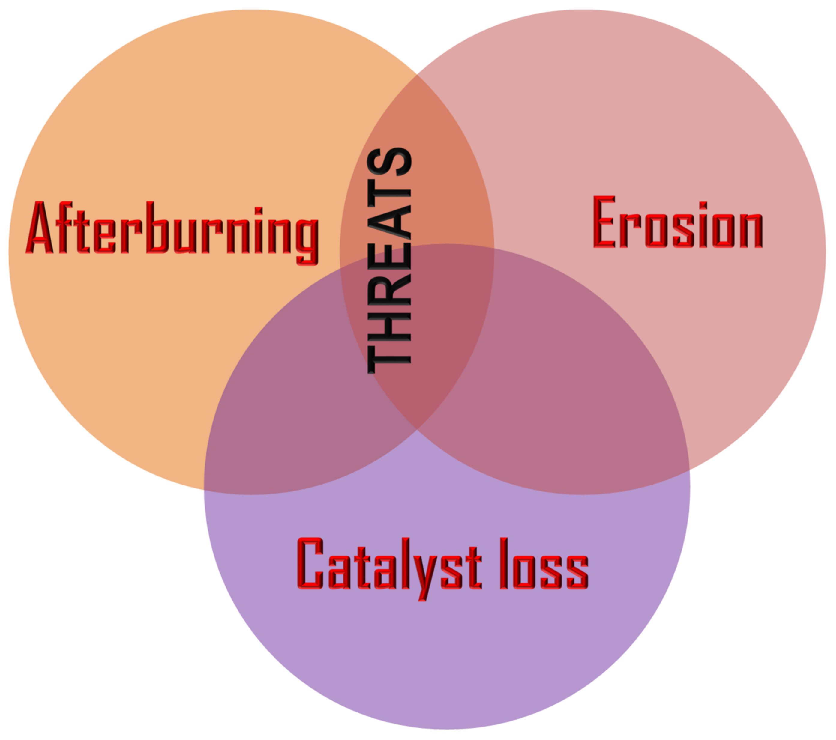
Figure 4. Major reliability issues in FCC regenerator.
4.1. After-Burn Control Measures
Afterburning (also called post-combustion) is a phenomenon associated with the localization of extremely high temperatures in the freeboard, usually as a result of post-combustion of carbon monoxide to produce carbon dioxide in the dilute phase, which can be intermittent or continuous. Entrained catalysts upon entering this zone by reason of prolong exposure to higher temperatures and overheating become incandescent and lose their activity or are completely damaged due to adverse alteration of their bulk density and porosity [54]; this holds true for every regenerator mode (either partial or full burn). Afterburning is mostly critical to the freeboard, thus affecting cyclones, plenum and overhead flue gas exit ducts. The dense bed, on the other hand, is immune because the heat of combustion liberated by regeneration is absorbed by the high catalyst inventory and holdup; therefore, extremely high temperature in the dense bed is uniformly distributed and ducked [34][54].
4.2. Anti-Erosion Measures
Continuous and rapid strike of gas and catalyst on the surface of the regenerator and the internals results in wear or material loss from the surfaces; this is otherwise termed erosion. Erosion due to particle strike is termed solid particle erosion (SPE); this is critical to basically cyclone, slide or plug valve, transfer lines, and expansion joint. Mechanical stresses induced by cavitation (implosion of gas bubbles) at high gas velocities are also critical, especially to the grid and air distributor nozzles.
4.3. Catalyst Losses and Countermeasures
Catalyst loss refers to the loss of catalyst particles (especially the finer and lighter solids (0–40 µm)) from the regenerator. Excess catalyst loss is a major problem facing refiners necessitating frequent device troubleshooting which not only reduces the unit profitability but also causes unscheduled shutdowns and elevated particulate emission [1]. High catalyst losses in the regenerator can be identified by: decrease in dense bed height, reduction in the amount of fine content, increase in the amount of large particle sizes (>80 µm) and the average particle size, and reduction in particle mixing stability and uniformity.
5. Environmental Issues
Increased knowledge of the environmental footprint of chemical processes has prompted the increasing demand for transformational change in refineries emissions. Irrespective of the design and size of FCC regenerators, the process of regenerating coked catalysts produces flue gases (including criteria particulates (0–20 µm size), CO, SOx, NOx and Ni compounds) and without an effective cleanup process available, they are emitted into the air at elevated levels. Nonetheless, in the face of the current pursuit of a net-zero emissions economy, ever-increasing stringent environmental requirements, and an influx of heavier crude oil, regenerator processes must be further intensified to increasingly reduce stack emissions.
5.1. Process Intensification for Particulate Matter (PM) Reduction
Catalyst dust is also known as fine dust or PM bound in the flue gas leaving the regenerator exit stack. They could also become obnoxious fugitive PM emissions during regenerator turnarounds and periodic withdrawal of aged catalysts or making up for losses [14]. They are carcinogenic due to the presence of nickel in the catalyst, making it a chemical health hazard. The regenerator is the highest emitter of PM in a refinery. Emission requirement for criterion small particulates (FCC fines, particularly PM10) depends on the governing regulating authorities and the refiners, but a common PM legislation is based on the amount of carbon combusted in the regenerator. In essence, for every 1000 lb coke combusted only 1 lb of PM or less (an equivalent of 95–125 and 80–500 mg/Nm3 for US and EU, respectively) can exit the FCC regenerator [55]. Stricter concentration of 50 mg/Nm3 has been reported elsewhere [55], and futuristically might further dip to 10 mg/Nm3 before 2050.
5.2. Process Intensification for SOx Reduction
Irrespective of the regeneration mode, spent catalysts must be de-oiled prior to regeneration to reject as many hydrocarbons as possible and to strip off sulfur compounds. This will forestall sulfate formation, which cannot be removed from the catalyst surface during regeneration with a deleterious effect on catalyst performance. However, small amounts of sulfur compounds still enter the regenerator and are converted to SOx flue gases.
Sulfur oxides (SOx) are made up of gaseous SO2 and SO3; the former is often used as the primary indicator due to its dominant proportion and toxicity. SOx is a precursor of secondary inorganic aerosol, acid rain and photochemical haze formation, which constitute environmental hazard [13].
5.3. Process Intensification for FCC Regenerator Flue Gas NOx Emission Reduction
Nitrogen oxides, generally referred to as NOx (NO + NO2 + N2O), are a leading ozone precursor and play a role in acid rain, smog and the formation of PM10 and PM2.5. FCC regenerator is the biggest single NOx emitter in the refinery in range of 100–500+ ppm, which is mainly NO. FCC feed often contains 0.05–0.5% organic nitrogen compounds, and about 50% of this is bounded into coke on catalyst.
This entry is adapted from the peer-reviewed paper 10.3390/en15062061
References
- Letzsch, W. Fluid Catalytic Cracking (FCC) in Petroleum Refining. In Handbook of Petroleum Processing; Treese, A., Pujadó, P.R., Jones, S.J.D., Eds.; Springer: London, UK, 2015; pp. 261–316.
- Grace, J.R.; Bi, X.; Ellis, N. Essentials of Fluidization Technology; KGaA: Boschstr. 12, 69469; Wiley-VCH Verlag GmbH & Co.: Weinheim, Germany, 2020.
- Li, J.; Ge, W.; Wang, W.; Yang, N.; Liu, X.; Wang, L.; He, X.; Wang, X.; Wang, J.; Kwauk, M. From Multiscale Modeling to Meso-Science; Hong Kong University of Science and Technology: Berlin-Heidelberg, Germany, 2013.
- Sabahi, A.; Loebl, A.J.; Galvada, S.; Francis, J.A.; Iyyamperumal, E. FCC Catalyst with More than One Silica, Its Preparation and Use. U.S. Patent 16/322,779, 4 July 2019.
- Hosseinpour, N.; Mortazavi, Y.; Khodadadi, A.A. Cumene cracking activity and enhanced regeneration of FCC catalysts comprising HY-zeolite and LaBO3 (B = Co, Mn, and Fe) perovskites. Appl. Catal. A Gen. 2014, 487, 26–35.
- Li, Z.; Lu, C.-X. FCC riser quick separation system: A review. Pet. Sci. Technol. 2016, 13, 776–781.
- Xie, J.; Zhong, W.; Yu, A. MP-PIC modeling of CFB risers with homogeneous and heterogeneous drag models. Adv. Powder Technol. 2018, 29, 2859–2871.
- Myers, D.N.; Palmas, P.; Johnson, D.R.; van Opdorp, P.J. Advanced Elevated Feed Distribution System for Very Large Diameter RCC Reactor Risers. U.S. Patent Application No. 11/541,052, 3 April 2008.
- Yang, C.; Chen, X.; Zhang, J.; Li, C.; Shan, H. Advances of two-stage riser catalytic cracking of heavy oil for maximizing propylene yield (TMP) process. Appl. Petrochem. Res. 2014, 4, 435–439.
- Hsu, C.S.; Robinson, P.R. Gasoline Production. In Petroleum Science and Technology; Springer: Berlin/Heidelberg, Germany, 2019; pp. 189–210.
- He, L.J.; Zheng, S.Q.; Dai, Y.L. An FCC catalyst for maximizing gasoline yield. J. Chem. Chem. Eng. 2017, 66, 9–15.
- Dean, C.; Letzsch, W.S. How to make anything with a catalytic cracker. In Hydrocarbon Processing; Gulf Publishing Co.: Houston, TX, USA, 2014.
- Sadeghbeigi, R. Fluid catalytic cracking handbook. In An Expert Guide to the Practical Operation, Design, and Optimization of FCC Units, 4th ed.; Butterworth-Heinemann: Oxford, UK, 2020.
- Jones, D.S.J.; Treese, S.A. Environmental Control and Engineering in Petroleum Processing. In Handbook of Petroleum Processing; Springer: Cham, Switzerland, 2015; pp. 1219–1308.
- Lesage, R.; Simon, H. Anchoring Structure for an Anti-Erosion Coating, in Particular for Protecting a Wall of an FCC Unit. U.S. Patent 10,799,846, 13 October 2020.
- Sadeghbeigi, R. Fluid Catalytic Cracking Handbook: An Expert Guide to the Practical Operation, Design, and Optimization of FCC Units; Elsevier: Amsterdam, The Netherlands, 2012.
- Dong, Q.; Bai, S.; Liu, Y.; Li, N.; Zhao, L.; Liu, S. Research progress of regenerator in FCC unit. J. Chem. Ind. Eng. 2013, 34, 1–4.
- Du, Y.; Sun, L.; Berrouk, A.S.; Zhang, C.; Chen, X.; Fang, D.; Ren, W. Novel integrated reactor-regenerator model for the fluidized catalytic cracking unit based on an equivalent reactor network. Energy Fuels 2019, 33, 7265–7275.
- Knowlton, T.M.; Karri, S.B.R. Standpipes and return systems, separation sevices, and feeders. In Essentials of Fluidization Technology; Wiley-VCH: Weinhard, Germany, 2020; pp. 203–237.
- Zhang, Y.; Zha, C.; Yu, S. Experimental study on a new FCC spent catalyst distributor. In Fluidization XV; Chaouki, J., Bi, X., Cocco, R., Eds.; SEMANTIC SCHOLAR: Seattle, WA, USA, 2016.
- Chen, Y.-M.; Patel, M.S. Spent Catalyst Distributor. U.S. Patent 6,797,239, 28 August 2004.
- Mirek, P. Air distributor pressure drop analysis in a circulating fluidized-bed boiler for non-reference operating conditions. Chem. Eng. Technol. 2020, 43, 2233–2246.
- Zhang, Y. Baffles and Aids to Fluidization. In Essentials of Fluidization Technology; Wiley-VCH: Weinhard, Germany, 2020; pp. 431–455.
- Miller, R.; Johnson, T.; Santner, C.; Avidan, A.; Beech, J. Comparison between Single and Two-Stage FCC Regenerators; National Petroleum Refiners Association: Washington, DC, USA, 1996.
- Pan, J.; Wu, G.; Yang, D. Thermal-hydraulic calculation and analysis on water wall system of 600 MW supercritical CFB boiler. Appl. Therm. Eng. 2015, 82, 225–236.
- Chinsuwan, A.; Dutta, A.; Janlasad, N. Prediction of the heat flux profile on the furnace wall of circulating fluidized bed boilers. J. Energy Inst. 2014, 87, 314–320.
- Ganapathy, V. Steam Generators and Waste Heat Boilers: For Process and Plant Engineers; CRC Press: Boca Raton, FL, USA, 2014.
- Kakac, S.; Liu, H.; Pramuanjaroenkij, A. Heat Exchangers: Selection, Rating, and Thermal Design; CRC Press: Boca Raton, FL, USA, 2020.
- Singh, R.; Gbordzoe, E. Modeling FCC spent catalyst regeneration with computational fluid dynamics. Powder Technol. 2017, 316, 560–568.
- Hedrick, B.W. Three-Stage Counter-Current FCC Regenerator. U.S. Patent 7,915,191, 29 March 2011.
- Miller, R.; Yang, Y.; Johnson, T. RegenMaxTM Technology, Staged Combustion in a Single Regenerator. In Proceedings of the 1999 NPRA Annual Meeting, San Antonio, TX, USA, 21–23 March 1999. AM-99-14.
- Raterman, M.F. Two-Stage Fluid Bed Regeneration of Catalyst with Shared Dilute Phase. U.S. Patent 5,198,397, 30 March 1993.
- Amblard, B.; Singh, R.; Gbordzoe, E.; Raynal, L. CFD modeling of the coke combustion in an industrial FCC regenerator. Chem. Eng. Sci. 2017, 170, 731–742.
- Sadeghbeigi, R. Process Description. In Fluid Catalytic Cracking Handbook; Butterworth-Heinemann: Oxford, UK, 2012.
- Letzsch, W. Fluid catalytic cracking (FCC). In Handbook of Petroleum Processing; Springer: Berlin/Heidelberg, Germany, 2008; pp. 239–286.
- Kalota, S.A.; Rahmim, I.I. Solve the five most common FCC problems. In Proceedings of the Advances in Fluid Catalytic Cracking I, New Orleans, LA, USA, 30 March–3 April 2003.
- Sexton, J.A. FCC cyclone using acoustic detectors. U.S. Patent 10,239,034, 26 March 2019.
- Chen, Y.M. Evolution of FCC-past present and guture and the challenges of operating a high temperature CFB system. In Proceedings of the 10th International Conferences on Circulating Fluidized Beds and Fluidization Technology, ECI Symposium Series, Sun River, OR, USA, 1–5 May 2013; p. 29.
- Li, G.; Yang, X.; Dai, G. CFD simulation of effects of the configuration of gas distributors on gas–liquid flow and mixing in a bubble column. Chem. Eng. Sci. 2009, 64, 5104–5116.
- Karri, S.R.; Werther, J. Gas distributor and plenum design in fluidized beds. In Handbook of Fluidization and Fluid-Particle Systems; Yang, W.-C., Ed.; Marcel Dekker: New York, NY, USA, 2003; pp. 155–170.
- Windows-Yule, C.R.K.; Gibson, S.; Werner, D.; Parker, D.J.; Kokalova, T.Z.; Seville, J.P.K. Effect of distributor design on particle distribution in a binary fluidised bed. Powder Technol. 2020, 367, 1–9.
- Sánchez-Delgado, S.; Marugán-Cruz, C.; Serrano, D.; Briongos, J.V. Distributor performance in a bubbling fluidized bed: Effects of multiple gas inlet jet and bubble generation. Chem. Eng. Sci. 2019, 195, 367–380.
- Cocco, R.; Shaffer, F.; Karri, S.R.; Hays, R.; Knowlton, T. Particle Clusters in Fluidized Beds. Proc. Int. Conf. Fluidization XIII—New Paradigm in Fluidization Engineering; ECI: Westover, MD, USA, 16–21 May 2010; pp. 45–48.
- Myers, D.N.; Tretyak, M.; Pittman, R.M.; Niewiedzial, S. FCC Spent Catalyst Distributor. U.S. Patent 7,368,090 B2, 6 May 2008.
- Bussey, B.K.; Glasgow, P.E.; Kalota, S.A.; Niccum, P.K. Spent Catalyst Distribution. U.S. Patent 5,773,378A, 30 June 1998.
- Zhang, Y.; Lu, C. Experimental study and modeling on effects of a new multilayer baffle in a turbulent fluid catalytic cracking regenerator. Ind. Eng. Chem. Res. 2014, 53, 2062–2066.
- Shah, M.T.; Pareek, V.K.; Evans, G.M.; Utikar, R.P. Effect of baffles on performance of fluid catalytic cracking riser. Particuology 2018, 38, 18–30.
- Harrison, D.; Grace, J.R. Fluidized beds with internal baffles. In Fluidization; Academic Press: Cambridge, UK, 1971.
- Miller, R.B.; Yang, Y.-L. Staged Catalyst Regeneration in a Baffled Fluidized Bed. U.S. Patent 6,503,460, 7 July 2003.
- Markham, C.L.; Muldowney, G.P. Baffled FCC Regeneration Process and Apparatus. U.S. Patent 5,288,397A, 22 February 1994.
- Veluswamy, G.K.; Upadhyay, R.K.; Utikar, R.P.; Evans, G.M.; Tade, M.O.; Glenny, M.E.; Roy, S.; Pareek, V.K. Hydrodynamics of a fluid catalytic cracking stripper using γ-ray densitometry. Ind. Eng. Chem. Res. 2011, 50, 5933–5941.
- Grace, J.R. Hydrodynamics of Bubbling Fluidization. In Essentials of Fluidization Technology; Wiley-VCH: Weinheim, Germany, 2020; pp. 131–152.
- Zhang, Z.; Wu, Z.; Rincon, D.; Christofides, P.D. Operational safety via model predictive control: The Torrance refinery accident revisited. Chem. Eng. Res. Des. 2019, 149, 138–146.
- Kassel, L.S. Prevention of Afterburning in Fluidized Catalytic Cracking Processes. U.S. Patent 2,436,927A, 2 March 1948.
- Sechrist, P.A.; Hedrick, B.W. Apparatus and Process for Separating Fine Solid Particulates from a Gas Stream. U.S. Patent 6,797,026, 28 September 2004.
This entry is offline, you can click here to edit this entry!