Glass technologies for 3D printing can be divided into several categories according to the printing method and the form of pre-treatment for the raw materials. These categories include powder-based, photopolymerization-based, and material extrusion-based 3D printing technology. Among them, fused deposition modeling (FDM), based on material extrusion (MEX), and selective laser sintering/melting (SLS/SLM), based on powder, usually require strict processing conditions and are therefore less suitable for laboratory processing. The most promising processing technologies are stereolithography (SLA), digital light processing (DLP), two-photon polymerization (TPP), sheet lamination (SL), which is based on photopolymerization, and DIW, based on MEX.
- 3D printing
- silica glass
- additive manufacturing
1. Introduction
| Categories | Glass 3D Printing Technology Type | Abbreviation |
|---|---|---|
| Powder based | Selective laser sintering | SLS |
| Selective laser melting | SLM | |
| Photopolymerization based | Stereolithography | SLA |
| Two-photon polymerization | TPP | |
| Digital light processing | DLP | |
| Sheet lamination | SL | |
| Material extrusion based | Direct ink writing | DIW |
| Fused deposition modeling | FDM |
2. Classification of 3D Printing Glass Technologies
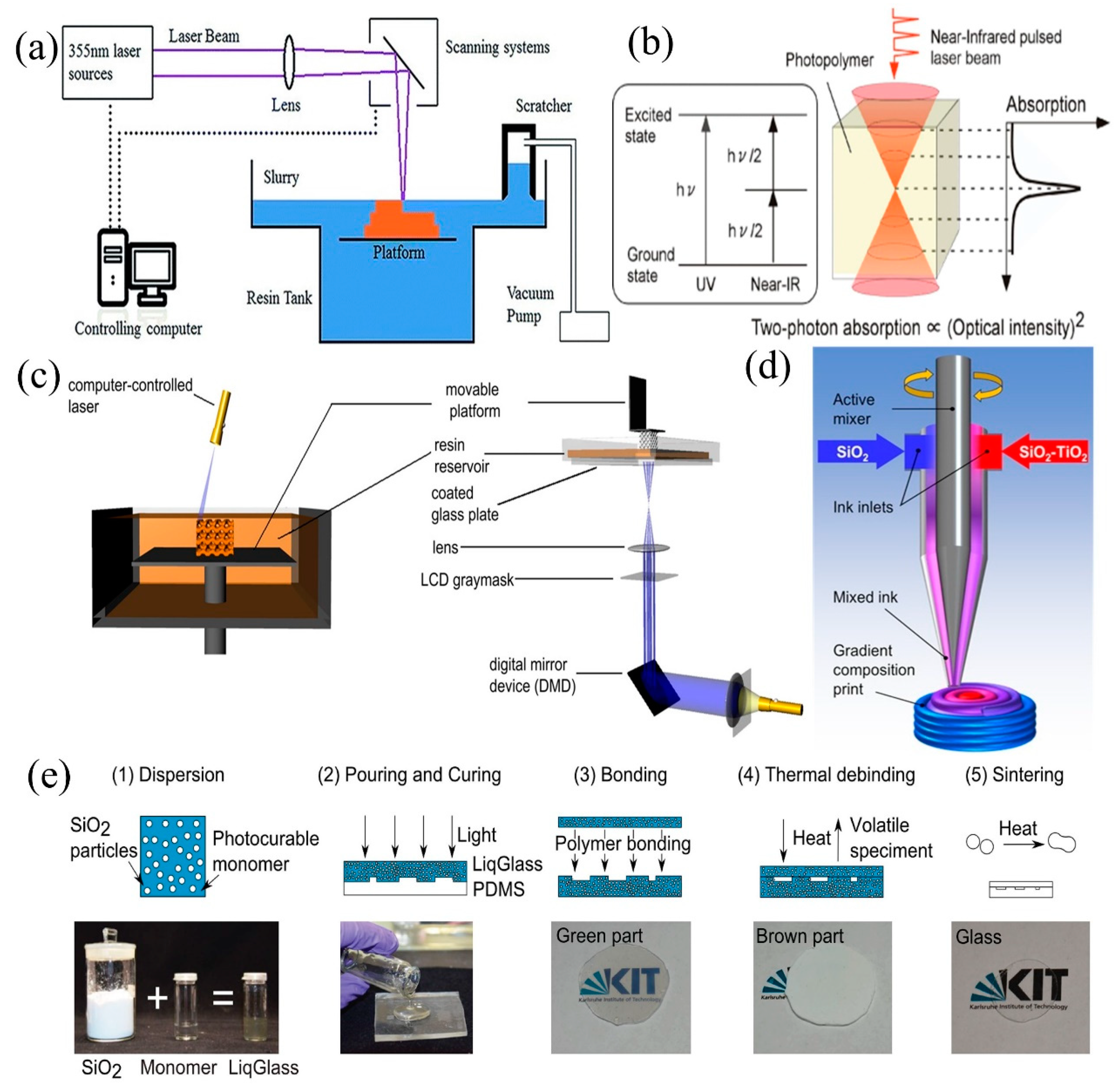
2.1. Micro-Stereolithography (μ-SLA)
2.1.1. Stereolithography (SLA)
2.1.2. Two-Photon Polymerization (TPP)
2.1.3. Digital Light Processing (DLP)
2.2. Direct Ink Writing (DIW)
2.3. Sheet Lamination (SL)
3. Applications of 3D Printing Glass Technologies
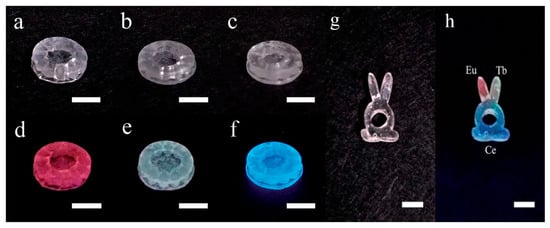
3.1. Applications of SLA Technology for Printing Glass
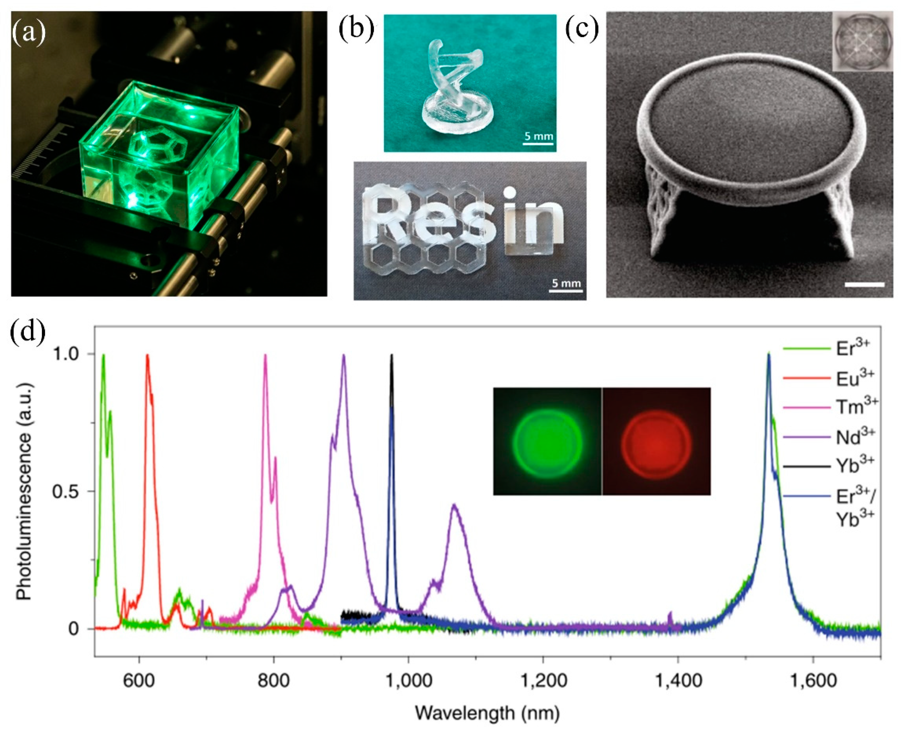
3.2. Applications of TPP Technology for Printing Glass
3.3. Applications of DLP Technology for Printing Glass
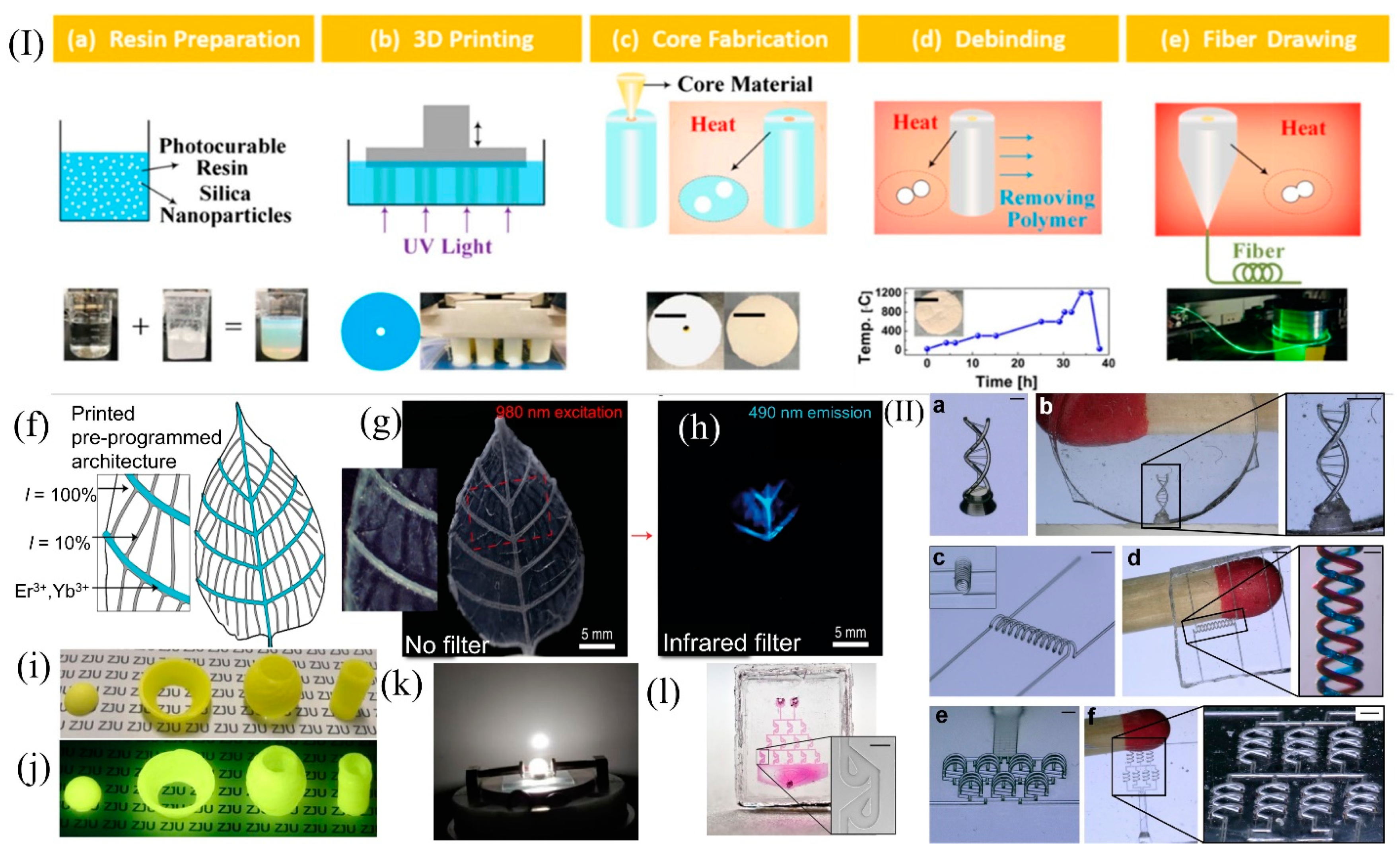
3.4. Applications of DIW Technology for Printing Glass
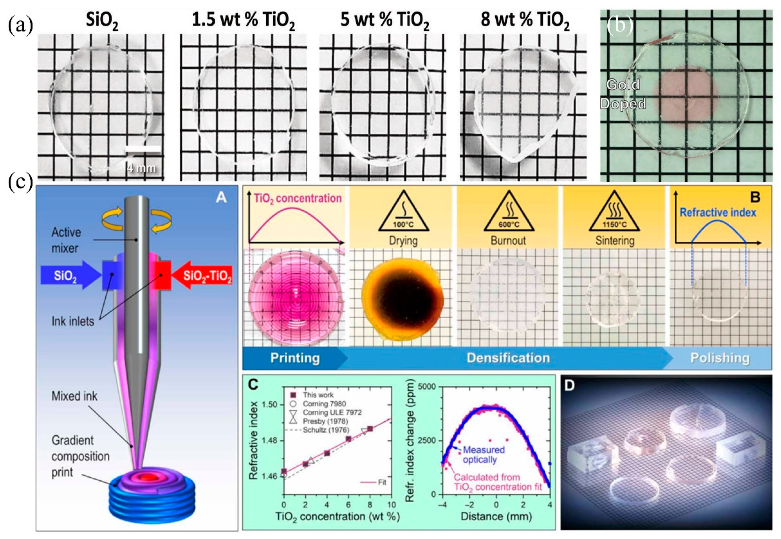
3.5. Applications of SL Technology for Printing Glass
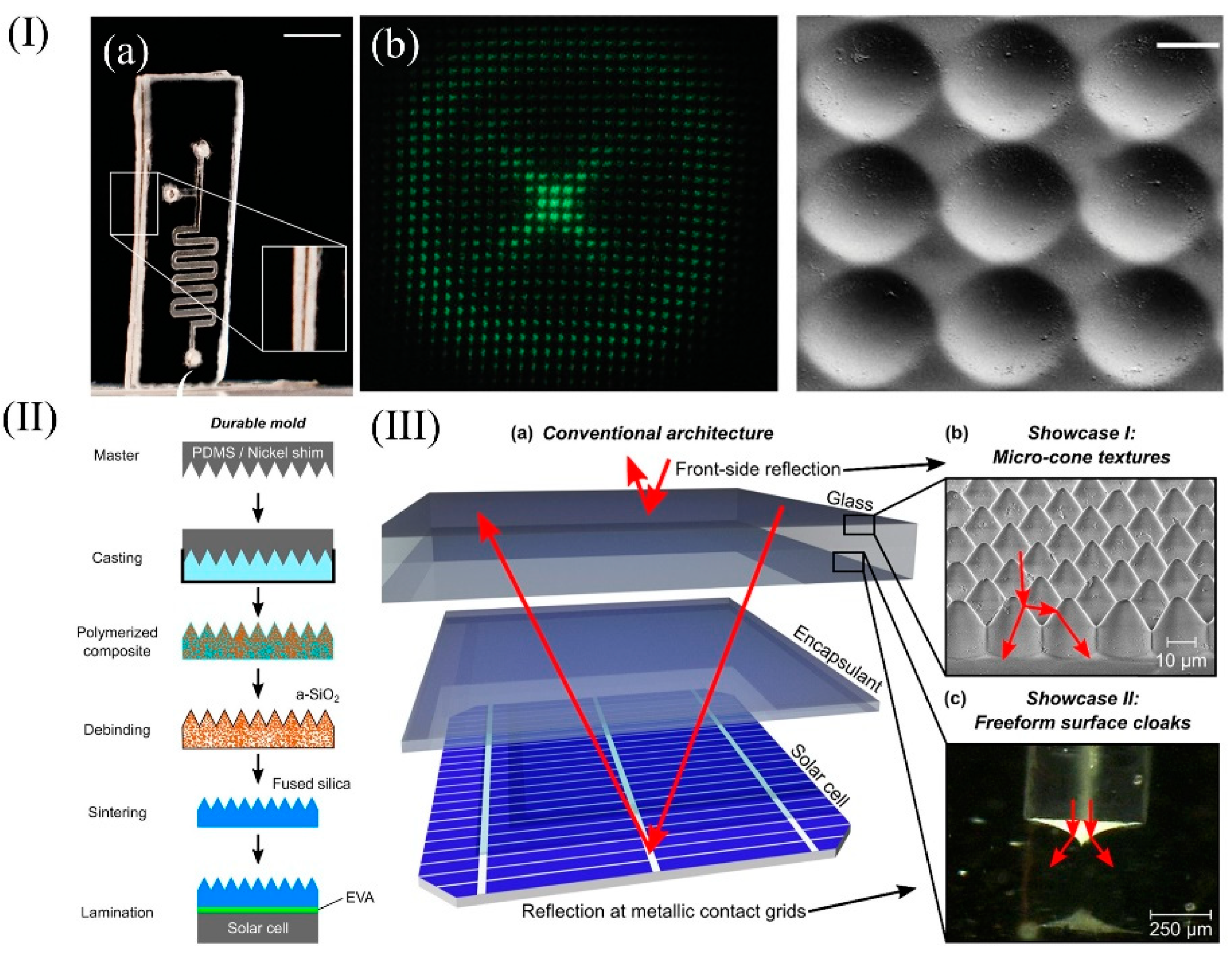
| Technology | Polymerization of Monomer | Dispersant | Photoinitiator | Stabilizer | Absorber | SiO2 | References |
|---|---|---|---|---|---|---|---|
| SLA | 29.5 wt%HEMA 1+ 3.7 wt% PEGDA 2 |
— | 0.4 wt% DMPA 3 |
13.1 wt% DEDB 4+ 0.4wt%MEHQ 5 |
0.3 wt% Tinuvin 1130 |
53.7 wt% Aerosil OX50 | [39] |
| 28.1 wt%HEMA+3.7 wt% PEGDA | — | 0.4 wt% DMPA |
14.5 wt% DEDB |
0.02 wt% Sudan red G |
53.7 wt% Aerosil OX50 | [76] | |
| DLP | 36.9 wt%HEMA+ 6.36 wt% TEGDA 6 |
19.0 wt% POE 7 |
0.2 wt% DPO 8 |
0.1 wt % hydroquinone |
— | 37.5wt% Aerosil OX50 | [34] |
| 60 vol%HEMA+ 10 vol%TEGDA |
30 vol% POE |
0.2 wt% Omnirad 819 9 |
0.1 wt% hydroquinone |
0.05 wt% Sudan Orange G |
37.5 vol% Aerosil OX50 | [35] | |
| 65 vol%HEMA+ 35 vol% TMPTA 10 |
— | 0.5 wt% Omnirad 819 |
0.5 wt% hydroquinone |
0.45 wt% Tinuvin 384-2 | 35 vol% Aerosil OX50 | [35] | |
| TPP | 80 wt%HEMA | 20 wt% POE |
1 wt% BDK 11 |
— | — | 50 wt% Aerosil OX50 | [56] |
| 333 mg ETPTA 12+ 666 mgPEGDA |
— | 10 mg EMK 13 |
5mg hydroquinone |
— | 1600 mg colloidal silica solution | [57] | |
| DIW | 79 wt%Tetraglyme | — | — | 1wt% PDMS | — | 21 wt%CAB-O-SIL EH-5 | [13] |
| 76 wt%Tetraglyme | — | — | 1wt% PDMS | — | 23 wt%CAB-O-SIL EH-5 | [13] | |
| SL | 68 vol%HEMA+ 7 vol%TEGDA |
25 vol% POE |
0.5 wt% DMPA |
— | — | 40 vol% Aerosil OX50 | [33] |
| 68 vol%HEMA+ 7 vol%TEGDA |
25 vol% POE |
0.5 wt% DMPA |
— | — | 50 vol% silica nanopowder (Zandosil) |
[90] |
This entry is adapted from the peer-reviewed paper 10.3390/mi13010081
References
- Frazier, W.E. Metal additive manufacturing: A review. J. Mater. Eng. Preform. 2014, 23, 1917–1928.
- Chen, Z.; Li, Z.; Li, J.; Liu, C.; Fu, Y.; Liu, C.; Li, Y.; Wang, P.; He, Y.; Lao, C. 3D printing of ceramics: A review. J. Eur. Ceram. Soc. 2019, 23, 661–687.
- Huang, S.H.; Liu, P.; Mokasdar, A.; Hou, L. Additive manufacturing and its societal impact: A literature review. Int. J. Adv. Manuf. Technol. 2013, 67, 1191–1203.
- Ligon, S.C.; Liska, R.; Stampfl, J.; Gurr, M.; Mülhaupt, R. Polymers for 3D printing and customized additive manufacturing. Chem. Rev. 2017, 117, 10212–10290.
- Martin, J.H.; Yahata, B.D.; Hundley, J.M.; Mayer, A.J.; Schaedler, T.A.; Pollock, T.M. 3D printing of high-strength aluminium alloys. Nature 2017, 549, 365–369.
- Hirt, L.; Reiser, A.; Spolenak, R.; Zambelli, T. Additive manufacturing of metal structures at the micrometer scale. Adv. Mater. 2017, 29, 1604211.
- Truby, R.L.; Lewis, J.A. Printing soft matter in three dimensions. Nature 2016, 540, 371.
- Wang, D.; Zhang, J.; Liu, Q.; Chen, B.; Liang, Y.; Hu, L.; Jiang, G. 3D printing challenges in enabling rapid response to public health emergencies. Innovation 2020, 1, 100056.
- Wang, X.; Jiang, M.; Zhou, Z.; Gou, J.; Hui, D. 3D printing of polymer matrix composites: A review and prospective. Compos. Part B-Eng. 2017, 110, 442–458.
- Yap, C.Y.; Chua, C.K.; Dong, Z.L.; Liu, Z.H.; Zhang, D.Q.; Loh, L.E.; Sing, S.L. Review of selective laser melting: Materials and applications. Appl. Phys. Rev. 2015, 2, 041101.
- Thiele, S.; Arzenbacher, K.; Gissibl, T.; Giessen, H.; Herkommer, A. 3D-printed eagle eye: Compound microlens system for foveated imaging. Sci. Adv. 2017, 3, e1602655.
- Thomas, R.; Li, J.; Ladak, S.; Barrow, D.; Smowton, P.M. In situ fabricated 3D micro-lenses for photonic integrated circuits. Opt. Express 2018, 26, 13436–13442.
- Nguyen, D.T.; Meyers, C.; Yee, T.D.; Dudukovic, N.A.; Destino, J.F.; Zhu, C.; Duoss, E.B.; Baumann, T.F.; Suratwala, T.; Smay, J.E.; et al. 3D-printed transparent glass. Adv. Mater. 2017, 29, 1701181.
- Dylla-Spears, R.; Yee, T.D.; Sasan, K.; Nguyen, D.T.; Dudukovic, N.A.; Ortega, J.M.; Johnson, M.A.; Herrera, O.D.; Ryerson, F.J.; Wong, L.L. 3D printed gradient index glass optics. Sci. Adv. 2020, 6, eabc7429.
- Sasan, K.; Lange, A.; Yee, T.D.; Dudukovic, N.; Nguyen, D.T.; Johnson, M.A.; Herrera, O.D.; Yoo, J.H.; Sawvel, A.M.; Ellis, M.E.; et al. Additive manufacturing of optical quality germania–silica glasses. Acs. Appl. Mater. Interfaces 2020, 12, 6736–6741.
- Zhang, D.; Xiao, W.; Liu, C.; Liu, X.; Ren, J.; Xu, B.; Qiu, J. Highly efficient phosphor-glass composites by pressureless sintering. Nat. Commun. 2020, 11, 2805.
- Wang, J.; Zheng, B.; Wang, P. 3D printed Er3+/Yb3+ co-doped phosphosilicate glass based on sol-gel technology. J. Non-Cryst. Solids 2020, 550, 120362.
- Wang, P.; Chu, W.; Li, W.; Tan, Y.; Liu, F.; Wang, M.; Qi, J.; Lin, J.; Zhang, F.; Cheng, Y. Three-Dimensional Laser Printing of Macro-Scale Glass Objects at a Micro-Scale Resolution. Micromachines 2019, 10, 565.
- Hong, Z.; Ye, P.; Loy, D.A.; Liang, R. Three-dimensional printing of glass micro-optics. Optica 2021, 8, 904–910.
- Zhang, Q.; Lei, J.; Chen, Y.; Wu, Y. 3D Printing of All-Glass Fiber-Optic Pressure Sensor for High Temperature Applications. IEEE Sens. J. 2019, 19, 11242–11246.
- Shao, G.; Hai, R.; Sun, C. 3D printing customized optical lens in minutes. Adv. Opt. Mater. 2020, 8, 1901646.
- Wong, K.V.; Hernandez, A. A review of additive manufacturing. ISRN Mech. Eng. 2012, 2012, 208760.
- Huang, J.; Qin, Q.; Wang, J. A review of stereolithography: Processes and systems. Processes 2020, 8, 1138.
- Zhou, L.Y.; Fu, J.; He, Y. A review of 3D printing technologies for soft polymer materials. Adv. Funct. Mater. 2020, 30, 2000187.
- Wang, Y.; John, G.; Pawlowski, M.E.; Tkaczyk, T.S. 3D printed fiber optic faceplates by custom controlled fused deposition modeling. Opt. Express 2018, 26, 15362–15376.
- Klein, J.; Stern, M.; Franchin, G.; Kayser, M.; Inamura, C.; Dave, S.; Weaver, J.; Houk, P.; Colombo, P.; Yang, M.; et al. Additive manufacturing of optically transparent glass. 3D Print. Addit. Manuf. 2015, 2, 92–105.
- Baudet, E.; Ledemi, Y.; Larochelle, P.; Morency, S.; Messaddeq, Y. 3D-printing of arsenic sulfide chalcogenide glasses. Opt. Mater. Express 2019, 9, 2307–2317.
- Luo, J.; Edward, H.P.; Kinzel, C. Additive manufacturing of glass. J. Manuf. Sci. Eng. 2014, 136, 061024.
- Luo, J.; Hostetler, J.M.; Gilbert, L.; Goldstein, J.T.; Urbas, A.M.; Bristow, D.A.; Landers, R.G.; Kinzel, E.C. Additive manufacturing of transparent fused quartz. Opt. Eng. 2018, 57, 041408.
- Luo, J.; Gilbert, L.J.; Qu, C.; Robert, G.L.; Douglas, A.B.; Edward, C.K. Additive manufacturing of optically transparent soda-lime glass using a filament-fed process. J. Manuf. Sci. Eng. 2017, 139, 061006.
- Kotz, F.; Schneider, N.; Striegel, A.; Wolfschläger, A.; Keller, N.; Worgull, M.; Bauer, W.; Schild, D.; Milich, M.; Greiner, C.; et al. Glassomer—processing fused silica glass like a polymer. Adv. Mater. 2018, 30, 1707100.
- Layani, M.; Wang, X.; Magdassi, S. Novel materials for 3D printing by photopolymerization. Adv. Mater. 2018, 30, 1706344.
- Kotz, F.; Plewa, K.; Bauer, W.; Schneider, N.; Keller, N.; Nargang, T.; Helmer, D.; Sachsenheimer, K.; Schäfer, M.; Worgull, M.; et al. Liquid glass: A facile soft replication method for structuring glass. Adv. Mater. 2016, 28, 4646–4650.
- Chu, Y.; Fu, X.; Luo, Y.; Canning, J.; Tian, Y.; Cook, K.; Zhang, J.; Peng, G. Silica optical fiber drawn from 3D printed preforms. Opt. Lett. 2019, 44, 5358–5361.
- Kotz, F.; Arnold, K.; Bauer, W.; Schild, D.; Keller, N.; Sachsenheimer, K.; Nargang, T.M.; Richter, C.; Helmer, D.; Rapp, B.E. Three-dimensional printing of transparent fused silica glass. Nature 2017, 544, 337–339.
- Cai, P.; Guo, L.; Wang, H.; Li, J.; Li, J.; Qiu, Y.; Zhang, Q.; Lue, Q. Effects of slurry mixing methods and solid loading on 3D printed silica glass parts based on DLP stereolithography. Ceram. Int. 2020, 46, 16833–16841.
- Cooperstein, I.; Shukrun, E.; Press, O.; Kamyshny, A.; Magdassi, S. Additive manufacturing of transparent silica glass from solutions. ACS Appl. Mater. Interfaces 2018, 10, 18879–18885.
- Gal-Or, E.; Gershoni, Y.; Scotti, G.; Nilsson, S.M.E.; Saarinen, J.; Jokinen, V.; Strachan, C.J.; Gennäs, G.B.; Yli-Kauhaluoma, J.; Kotiaho, T. Chemical analysis using 3D printed glass microfluidics. Anal. Methods 2019, 11, 1802–1810.
- Liu, C.; Qian, B.; Liu, X.; Tong, L.; Qiu, J. Additive manufacturing of silica glass using laser stereolithography with a top-down approach and fast debinding. RSC Adv. 2018, 8, 16344–16348.
- Maruo, S.; Fourkas, J.T. Recent progress in multiphoton microfabrication. Laser Photonics Rev. 2008, 2, 100–111.
- Melchels, F.P.W.; Feijen, J.; Grijpma, D.W. A review on stereolithography and its applications in biomedical engineering. Biomaterials 2010, 31, 6121–6130.
- Jariwala, S.H.; Lewis, G.S.; Bushman, Z.J.; Adair, J.H.; Donahue, H.J. 3D printing of personalized artificial bone scaffolds. 3D Print Addit. Manuf. 2015, 2, 56–64.
- Pham, D.T.; Gault, R.S. A comparison of rapid prototyping technologies. Int. J. Mach. Tools Manuf. 1998, 38, 1257–1287.
- Oropallo, W.; Piegl, L.A. Ten challenges in 3D printing. Eng. Comput. 2016, 32, 135–148.
- Rengier, F.; Mehndiratta, A.; Tengg-Kobligk, H.V.; Zechmann, C.M.; Unterhinninghofen, R.; Kauczor, H.U.; Giesel, F.L. 3D printing based on imaging data: Review of medical applications. Int. J. Comput. Assisted Radiol. Surg. 2010, 5, 335–341.
- Griffith, M.L.; Halloran, J.W. Freeform fabrication of ceramics via stereolithography. J. Am. Ceram. Soc. 1996, 79, 2601–2608.
- Eckel, Z.C.; Zhou, C.; Martin, J.H.; Jacobsen, A.J.; Carter, W.B.; Schaedler, T.A. Additive manufacturing of polymer-derived ceramics. Science 2016, 351, 58–62.
- Brady, G.A.; Halloran, J.W. Stereolithography of ceramic suspensions. Rapid Prototyp. J. 1997, 3, 61–65.
- Halloran, J.W.; Tomeckova, V.; Gentry, S.; Das, S.; Cilino, P.; Yuan, D.; Guo, R.; Rudraraju, A.; Shao, P.; Wu, T.; et al. Photopolymerization of powder suspensions for shaping ceramics. J. Eur. Ceram. Soc. 2011, 31, 2613–2619.
- Bae, C.J.; Ramachandran, A.; Halloran, J.W. Quantifying particle segregation in sequential layers fabricated by additive manufacturing. J. Eur. Ceram. Soc. 2018, 38, 4082–4088.
- Maruo, S.; Nakamura, O.; Kawata, S. Three-dimensional microfabrication with two-photon-absorbed photopolymerization. Opt. Lett. 1997, 22, 132–134.
- Schizas, C.; Melissinaki, V.; Gaidukeviciute, A.; Reinhardt, C.; Ohrt, C.; Dedossis, V.; Chichkov, B.N.; Fotakis, C.; Farsari, M.; Karalekas, D. On the design and fabrication by two-photon polymerization of a readily assembled micro-valve. Int. J. Adv. Manuf. Technol. 2010, 48, 435–441.
- Seet, K.K.; Mizeikis, V.; Matsuo, S.; Juodkazis, S.; Misawa, H. Three-dimensional spiral-architecture photonic crystals obtained by direct laser writing. Adv. Mater. 2005, 17, 541–545.
- Kawata, S.; Sun, H.B.; Tanaka, T.; Takada, K. Finer features for functional microdevices. Nature 2001, 412, 697–698.
- Gan, Z.; Cao, Y.; Evans, R.A.; Gu, M. Three-dimensional deep sub-diffraction optical beam lithography with 9 nm feature size. Nat. Commun. 2012, 4, 2061.
- Doualle, T.; André, J.C.; Gallais, L. 3D printing of silica glass through a multiphoton polymerization process. Opt. Lett. 2021, 46, 364–367.
- Wen, X.; Zhang, B.; Wang, W.; Ye, F.; Yue, S.; Guo, H.; Gao, G.; Zhao, Y.; Fang, Q.; Nguyen, C.; et al. 3D-printed silica with nanoscale resolution. Nat. Mater. 2021, 20, 1506–1511.
- Wu, D.; Zhao, Z.; Zhang, Q.; Qi, H.J.; Fang, D. Mechanics of shape distortion of DLP 3D printed structures during UV post-curing. Soft Matter 2019, 15, 6151–6159.
- Komissarenko, D.A.; Sokolov, P.S.; Evstigneeva, A.D.; Shmeleva, I.A.; Dosovitsky, A.E. Rheological and curing behavior of acrylate-based suspensions for the DLP 3D printing of complex zirconia parts. Materials 2018, 11, 2350.
- Nakamoto, T.; Yamaguchi, K. Consideration on the producing of high aspect ratio micro parts using UV sensitive photopolymer. In Proceedings of the 7th International Symposium on Micro Machine and Human Science, Nagoya, Japan, 2–4 October 1996; pp. 53–58.
- Son, J.Y.; Lee, B.R.; Chernyshov, O.O.; Moon, K.A.; Lee, H. Holographic display based on a spatial DMD array. Opt. Lett. 2013, 38, 3173–3176.
- Ri, S.; Fujigaki, M.; Matui, T.; Morimoto, Y. Pixel-to-pixel correspondence adjustment in DMD camera by moiré methodology. Exp. Mech. 2006, 46, 67–75.
- Sun, C.; Fang, N.; Wu, D.; Zhang, X. Projection micro-stereolithography using digital micro-mirror dynamic mask. Sens. Actuators A Phys. 2005, 121, 113–120.
- Sadeqi, A.; Nejad, R.H.; Owyeung, R.E.; Sonkusale, S. Three dimensional priting of metamaterial embedded geometrical optics (MEGO). Microsyst. Nanoeng. 2019, 5, 16.
- Waheed, S.; Cabot, J.M.; Macdonald, N.P.; Lewis, T.; Guijt, R.M.; Paull, B.; Breadmore, M.C. 3D printed microfluidic devices: Enablers and barriers. Lab Chip 2016, 16, 1993–2013.
- Manapat, J.Z.; Chen, Q.; Ye, P.; Advincula, R.C. 3D printing of polymer nanocomposites via stereolithography. Macromol. Mater. Eng. 2017, 302, 1600553.
- Sharafeldin, M.; Kadimisetty, K.; Bhalerao, K.S.; Chen, T.; Rusling, J.F. 3D-printed Immunosensor arrays for cancer diagnostics. Sensors 2020, 20, 4514.
- Nan, B.; Galindo-Rosales, F.J.; Ferreira, J.M.F. 3D printing vertically: Direct ink writing free-standing pillar arrays. Mater. Today 2020, 35, 16–24.
- Zhu, J.; Zhang, Q.; Yang, T.; Liu, Y.; Liu, R. 3D printing of multi-scalable structures via high penetration near-infrared photopolymerization. Nat. Commun. 2020, 11, 3462.
- Kim, Y.; Yuk, H.; Zhao, R.; Chester, S.A.; Zhao, X. Printing ferromagnetic domains for untethered fast-transforming soft materials. Nature 2018, 558, 274–279.
- Hardin, J.O.; Ober, T.J.; Valentine, A.D.; Lewis, J.A. Microfluidic printheads for multimaterial 3D printing of viscoelastic inks. Adv. Mater. 2015, 27, 3279–3284.
- Kowsari, K.; Akbari, S.; Wang, D.; Fang, N.X.; Ge, Q. High-efficiency high-resolution multimaterial fabrication for digital light processing-based three-dimensional printing. 3D Print. Addit. Manuf. 2018, 5, 185–193.
- Ma, X.; Qu, X.; Zhu, W.; Li, Y.-S.; Yuan, S.; Zhang, H.; Liu, J.; Wang, P.; Lai, C.S.E.; Zanella, F.; et al. Deterministically patterned biomimetic human iPSC-derived hepatic model via rapid 3D bioprinting. Proc. Natl. Acad. Sci. USA 2016, 113, 2206–2211.
- Destino, J.F.; Dudukovic, N.A.; Johnson, M.A.; Nguyen, D.T.; Yee, T.D.; Egan, G.C.; Sawvel, A.M.; Steele, W.A.; Baumann, T.F.; Duoss, E.B.; et al. 3D printed optical quality silica and silica-titania glasses from sol-gel feedstocks. Adv. Mater. Technol. 2018, 3, 1700323.
- Beh, W.S.; Kim, I.T.; Qin, D.; Xia, Y.; Whitesides, G.M. Formation of patterned microstructures of conducting polymers by soft lithography, and applications in microelectronic device fabrication. Adv. Mater. 1999, 11, 1038–1041.
- Liu, C.; Qian, B.; Ni, R.; Liu, X.; Qiu, J. 3D printing of multicolor luminescent glass. RSC Adv. 2018, 8, 31564–31567.
- Zhang, A.P.; Qu, X.; Soman, P.; Hribar, K.C.; Lee, J.W.; Chen, S.; He, S. Rapid fabrication of complex 3D extracellular microenvironments by dynamic optical projection stereolithography. Adv. Mater. 2012, 24, 4266–4270.
- Lee, M.P.; Cooper, G.J.; Hinkley, T.; Gibson, G.M.; Padgett, M.J.; Cronin, L. Development of a 3D printer using scanning projection stereolithography. Sci. Rep. 2015, 5, 9875.
- Zhang, D.; Liu, X.; Qiu, J. 3D printing of glass by additive manufacturing techniques: A review. Front. Optoelectron. 2021, 14, 263–277.
- Kotz, F.; Risch, P.; Arnold, K.; Sevim, S.; Puigmartí-Luis, J.; Quick, A.; Thiel, M.; Hrynevich, A.; Dalton, P.D.; Helmer, D.; et al. Fabrication of arbitrary three-dimensional suspended hollow microstructures in transparent fused silica glass. Nat. Commun. 2019, 10, 1439.
- Moore, D.G.; Barbera, L.; Masania, K.; Studart, A.R. Three-dimensional printing of multicomponent glasses using phase-separating resins. Nat. Mater. 2020, 19, 212–217.
- Helmer, D.; Voigt, A.; Wagner, S.; Keller, N.; Sachsenheimer, K.; Kotz, F.; Nargang, T.M.; Rapp, B.E. Suspended liquid subtractive lithography: One-step generation of 3D channel geometries in viscous curable polymer matrices. Sci. Rep. 2017, 7, 7387.
- Saggiomo, V.; Velders, A.H. Simple 3D printed scaffold-removal method for the fabrication of intricate microfluidic devices. Adv. Sci. 2015, 2, 1500125.
- Patrick, J.F.; Krull, B.P.; Garg, M.; Mangun, C.L.; Moore, J.S.; Sottos, N.R.; White, S.R. Robust sacrificial polymer templates for 3D interconnected microvasculature in fiber-reinforced composites. Compos. Part A Appl. Sci. Manuf. 2017, 100, 361–370.
- Hedayat, N.; Du, Y.; Ilkhani, H. Review on fabrication techniques for porous electrodes of solid oxide fuel cells by sacrificial template methods. Renew. Sustain. Energy Rev. 2017, 77, 1221–1239.
- Gong, H.; Bickham, B.P.; Woolley, A.T.; Nordin, G.P. Custom 3D printer and resin for 18 μm × 20 μm microfluidic flow channels. Lab Chip 2017, 17, 2899–2909.
- Wang, W.; Tafti, G.; Ding, M.; Luo, Y.; Tian, Y.; Wang, S.; Karpisz, T.; Canning, J.; Cook, K.; Peng, G.D. Structure formation dynamics in drawing silica photonic crystal fibres. Front. Optoelectron. 2018, 11, 69–76.
- Waldbaur, A.; Carneiro, B.; Hettich, P.; Wilhelm, E.; Rapp, B.E. Computer-aided microfluidics (CAMF): From digital 3D-CAD models to physical structures within a day. Microfluid. Nanofluid. 2013, 15, 625–635.
- Martelli, C.; Canning, J. Fresnel fibres with omnidirectional zone cross-sections. Opt. Express 2007, 15, 4281–4286.
- Langenhorst, M.; Ritzer, D.; Kotz, F.; Risch, P.; Dottermusch, S.; Roslizar, A.; Schmager, R.; Richards, B.S.; Rapp, B.E. Liquid Glass for Photovoltaics: Multifunctional Front Cover Glass for Solar Modules. ACS Appl. Mater. Interfaces 2019, 11, 35015–35022.
- Li, X.M.; Reinhoudt, D.; Crego-Calama, M. What Do We Need for a Superhydrophobic Surface? A Review on the Recent Progress in the Preparation of Superhydrophobic Surfaces. Chem. Soc. Rev. 2007, 36, 1350–1368.
- Wang, R.; Hashimoto, K.; Fujishima, A.; Chikuni, M.M.; Kojima, E.; Kitamura, A.; Shimohigoshi, M.; Watanabe, T.; Wilbur, J.L.; Biebuyck, H.A.; et al. Light-Induced Amphiphilic Surfaces. Nature 1997, 388, 431–432.
- Roslizar, A.; Dottermusch, S.; Vüllers, F.; Kavalenka, M.N.; Guttmann, M.; Schneider, M.; Paetzold, U.W.; Hölscher, H.; Richards, B.S.; Klampaftis, E. Self-Cleaning Performance of Superhydrophobic Hot-Embossed Fluoropolymer Films for Photo-voltaic Modules. Sol. Energy Mater. Sol. Cells 2019, 189, 188–196.
