Your browser does not fully support modern features. Please upgrade for a smoother experience.
Please note this is an old version of this entry, which may differ significantly from the current revision.
Subjects:
Materials Science, Biomaterials
Lanthanide-doped nanoparticles exhibit unique luminescent properties, including tunable luminescence emission, narrow emission width, excellent optical stability, and long lifetimes from microseconds to milliseconds. Lanthanide-doped nanomaterials with long lifetimes are independent with background fluorescence interference and biological tissue depth.
- luminescence lifetime
- lanthanide-doped nanoparticles
- lifetime regulation
- bioimaging
1. Introduction
A central goal in biology and medicine is to develop excellent imaging and detection technology [1]. Researchers have devoted massive efforts to developing fluorescence imaging technology through fluorescent nanomaterials, including quantum dots (QDs) [2], upconversion nanomaterials (UCNPs) [3], carbon-based nanomaterials [4], stoichiometric metal oxides [5], perovskite [6], metal nanomaterials [7] and other materials [8]. In addition, biological images were obtained in a non-invasive manner under laser excitation [9], which has great labeling ability, high signal strength, fast imaging speed and a wide range of applications [10,11,12,13]. However, there are numerous limitations based on conventional fluorescence imaging technology, including low sensitivity, shallow detective depth and substantial interference caused by background autofluorescence [14,15]. Among the large number of nanomaterials, lanthanide-doped nanoparticles feature a longer lifetime than other fluorescence materials, whose emission could last for milliseconds [16].
Unsusceptible to the concentration of nanoparticles [19], laser intensity [20] and biological tissue thickness [21], the quality of luminescence lifetime imaging is better than traditional luminescence imaging in the cell or tissue microenvironment [22]. Moreover, the sensitivity of time-gated imaging with an optical chopper offers more than one order of magnitude than that of the traditional method using optical band-pass filters [23].
Researchers focus on the recent advances in the regulating lifetime of lanthanide for biosensing and imaging (Figure 1).
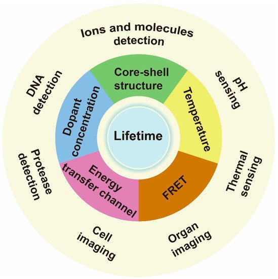
Figure 1. Schematic illustrations of lanthanide-doped nanoparticle lifetime regulation for biosensing. The approaches to regulating lifetime include varying core–shell structure, dopant concentration, energy transfer channel, temperature and setting a fluorescence resonance energy transfer (FRET) system. The relevant applications include ions, molecules, DNA, protease, thermal and pH sensing, as well as cell labeling and organ imaging.
2. Lifetime Regulation
Luminescence lifetime refers to the average time the molecule spends in the excited state returning to the ground state [26]. The lifetime of a phosphor, τ, refers to the time at which the intensity decays to 1/e of its maximum [27]. The decay of one emitting state in an upconversion energy transfer process is determined by its intrinsic decay and the intermediate states [28]. Susceptive to their intrinsic properties and local environment, the lifetime of lanthanide-doped nanoparticles could be tuned by adjusting core–shell structure, the content of sensitizer and emitter, internal energy transfer channel, FRET system and temperature. Nanocrystals with a controllable lifetime have been widely used in biosensing to eliminate background autofluorescence and light scattering interference. However, the reported methods allow only a limited range of lifetime adjustments.
2.1. Variation of Core–Shell Structures
Core–shell engineering is generally utilized to reduce surface quenching effects [29]. Shell passivation could promote the upconversion process by promoting the occurrence of energy hopping in higher-lying excited states [30]. Therefore, lifetime is affected by the shell layers, including the shell thickness and shell composition.
2.1.1. Core Size
The defect density of core nanoparticles doped with sensitizers and emitters decreases as the nanoparticle’s size increases. Jin et al. found an increase in the lifetime of Yb, Er-doped UCNPs with the increase of their size by comparing the lifetime of these nanoparticles ranging from 6 nm to 45 nm (Figure 2a). With the assistance of a mathematical model, it was verified that the decay time was related to surface-to-volume ratio and shell thickness. In addition, the lifetime of β-phase particles has significant relationships with surface defect, solvent and vibration energy of surface ligands, while defect density only matters for α-phase nanocrystals [31]. Liu et al. compared the decay curves of different sizes of NaYF4: 20%Yb,2%Er ranging from 15.3 nm to 27.2 nm, exhibiting the increase in the lifetime of both Er3+ and Yb3+ at 540 nm and 985 nm, respectively, as the nanoparticle dimension expanded [32].
2.1.2. Inert Shell Passivation
The epitaxial shell could protect the excitation energy from trapping by surface ligands or solvent molecules, leading to a long-lived lifetime. Su et al. designed a core–shell–shell heterostructure to prolong the lifetime of upconversion emitters. An optically inert NaYF4 shell on the surface of NaGdF4@NaGdF4 core–shell nanoparticle could efficiently block the energy transfer from Gd3+ to surface quenchers, thereby promoting efficient upconversion emission and long lifetimes of Gd3+ [33]. Mao et al. successively compared the decay curves of NaYF4: Yb/Er/Mn (Cd), NaYF4@NaYF4: Yb/Er/Mn (C/Sd), NaYF4: Yb/Er/Mn@NaYF4 (Cd/S) and NaYF4@NaYF4: Yb/Er/Mn@NaYF4 (C/Sd/S), finding the lifetime became longer. Amongst them, the C/Sd/S structure has two layers of NaYF4 interface contacting the active shell, which reduced surface defects and thus enhanced the upconversion process. Therefore, the lifetime can be prolonged by reducing energy defects and increasing the energy transfer rate [34].
CaF2 is a biocompatible and fluoride-rich matrix that is well used as a shell in upconversion nanomaterials, which can simultaneously suppress the interfacial diffusion of Ln3+ and surface quenching [35]. After heterogenous CaF2 layer was coated on the NaGdF4: Yb,Er, the lifetime of Er3+ at 532 nm prolonged from 89 μs to 162 μs, accompanied by the green (2H11/2, 4S3/2→4I15/2) and red (4I15/2→4I15/2) emissions of Er3+ enhanced 24.2 and 55.5 times, respectively [36]. When CaF2 grew on the core of NaYF4: 10%Yb,30% Nd, the lifetime of Yb3+ at 1000 nm increased from 51 μs up to 833 μs, indicating the surface lattice defects were minimized [37].
Interestingly, Su et al. provided an upconverted excitation lock-in (UCEL) mode to block the energy consumption of Gd3+ caused by lattice defects and impurities. NaYF4-based interlayer can effectively suppress the energy loss within the nanoparticles induced by inner lattice defects and promote energy recycling in the core domain. Therefore, the lifetime and the emission intensity of the heterogeneous structure significantly increased compared with the homogeneous counterparts (Figure 2b) [38].
Increasing shell thickness could suppress the non-radiative effect and cross-relaxation. Liu et al. synthesized NaYF4: Yb3+,Er3+@mNaYF4 (m = 0, 1, 2, 3, 4, 5) core–shell nanoparticles with different shell thicknesses (7.5 nm, 9 nm, 10 nm, 11 nm, 11.8 nm and 16.5 nm). The corresponding lifetimes of these nanoparticles were measured to be 10.10 μs, 11.57 μs, 15.78 μs, 19.77 μs, 23.51 μs and 26.52 μs due to the protection of shell [39]. Furthermore, increasing heterogenous shell thickness could minimize surface quenching. Coating a CaF2 shell with a range of thickness from 0 nm to 5.3 nm on the NaYbF4, the lifetime of Yb3+ of 980 nm increased from 33 μs to 2.18 ms, excited at 920 nm measured by an optical parametric oscillator (OPO) laser. Therein, when the CaF2 shell thickness reached 2.6 nm, the luminescence lifetime value was approximate to the radiative lifetime of Yb3+ [40].
2.1.3. Active Shell
With regard to the active shell, Liu et al. proved that increasing the concentration of sensitizer in the shell had adverse impacts on the luminescence intensity and lifetime enhancement. In a NaYF4: 20%Yb,2%Er@NaYF4: m%Yb (m = 0, 10, 20) nanoparticle, the lifetime of Er3+ and Yb3+ at 540 nm and 985 nm decreased when the concentration of Yb3+ in the shell increased. This can be attributed to the fact that more sensitizers in the shell increased the possibility of energy trapped by the surface defect. In addition, a lower energy transfer efficiency was observed due to the longer distance between sensitizer and emitter compared with that in the counterpart consisting of inner sensitizers [32].
A longer migration distance imparted by thicker energy migration layers or an increased number of migration steps may prolong luminescence lifetime. In a core/multishell NaYF4@NaYbF4@NaYF4: Yb3+/Tm3+@NaYF4 nanoparticle, the thickness of the energy migration layer (NaYbF4) increased from 0, 1.5, 3.0, 5.0 to 8.0 nm gradually, and the lifetime at 808 nm increased from 867, 1027, 1162, 1201 to 1282 µs, respectively [41]. When the thickness of the shell doped with sensitizers (i.e., Yb3+) increased, the lifetime of activators was longer in the core due to Yb energy migration. Increasing the thickness of the second layer in the β-NaGdF4: 25%Yb,1%Tm@NaYF4: 10%Yb@ NaNdF4: 10%Yb@NaYF4 from 1.5 nm to 5.4 nm, the lifetime at 475 nm prolonged from 632 μs to 836 μs [42]. In addition, with NaGdF4@NaGdF4: Yb,Er@NaYF4: Yb@NaNdF4: Yb used as an experimental model, the lifetime at 1525 nm was enhanced when increasing the thickness of the energy relay layer (NaYF4: Yb), which was attributed to the enlarged distance from sensitizers to emitters. A similar trend was also observed in Ho3+-doped nanoparticles (Figure 2c). Meanwhile, a certain Yb3+-doped shell thickness corresponded to the determined capacity of Yb3+ sublattice. Therefore, increasing the concentration of emitters could accelerate the stored energy into luminescence emission, resulting in a shortened lifetime. As the proportion of Er3+ rose from 0.5% up to 32%, the lifetime at 540 nm decreased from 101 μs to 13 μs [43].
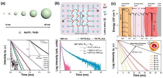
Figure 2. (a) The schematic description for the size of NaYF4: Yb,Er nanoparticles and lifetime decay curves of green emission in these nanoparticles. Reproduced with permission from [31]. Copyright 2013, Royal Society of Chemistry. (b) The diagram of energy transfer mechanism in NaGdF4: 49%Yb,1%Tm coated with heterogeneous shell nanoparticle, and corresponding lifetimes of Gd3+ in homogenerous and heterogeneous nanoparticles at 310 nm under 808 nm excitation. Reproduced with permission from [38]. Copyright 2021, Nature Publishing Group. (c) The diagrammatic drawing of energy transfer process in the core–multishell nanoparticles and luminescence decay curves at 1525 nm with the energy relay shell thickness ranging from 0 nm to 7 nm. Reproduced with permission from [43]. Copyright 2018, Nature Publishing Group.
2.2. Changing Concentration of Sensitizer and Emitter
Excessive emitters would increase the probability of cross-relaxation, leading to concentration quenching. For a Yb3+-Er3+-Ho3+ tri-doped nanoparticle, higher content of Ho3+ could shorten the interionic distances of Yb3+-Er3+/Ho3+, Er3+-Ho3+ and Ho3+-Ho3+, which could enhance the non-radiative process and energy transfer (ET) sensitization. A decrease in the lifetime of Ho3+ (643 nm, 750 nm, 895 nm), Er3+(525 nm, 545 nm, 655 nm, 810 nm, 845 nm) and Yb3+ (1020 nm) was observed when increasing the concentration of Ho3+ [44]. Similarly, as the mole content of Tm3+ rose from 0.2% to 8% in NaYF4: 20%Yb,x%Tm (40 nm), the lifetime of the blue emission was reduced from 662.4 µs to 25.6 µs (Figure 3a). Meanwhile, as the mole percentage of Yb3+ rose from 10% to 30% in NaYF4: x%Yb,1%Tm, the lifetime of the same blue emission decreased from 206.7 µs to 120.2 µs [20]. The higher concentration of part of emitters would likely cause self-aggregation and cross relaxation, resulting in a shortened lifetime. When the Er3+ concentration was varying from 1% to 70% in the β-NaYbF4@NaY0.8−xErxGd0.2F4@ NaY0.8Gd0.2F4, the lifetime of Er3+ at the level of 4S3/2 (540 nm) decreased sequentially. The shorter lifetime was attributed to the noneffective passivation on the surface when dopant with a higher concentration of emitters. Due to the greater energy from Yb3+ (2F5/2) being transferred to Er3+ (4S3/2, 4S9/2), the lifetime of Yb3+ was shortened. With the lack of cross-relaxation pathways for the 4S9/2 level of Er3+, the lifetime rarely has significant changes with the Er3+ concentration variation. Interestingly, the lifetime of Er3+ at 654 nm in the β-NaYbF4@NaY0.8−xErxGd0.2F4 structure had a long lifetime due to more incredible energy transferring to the surface [45].
Simultaneous excitation of two Yb3+ ions can produce Yb3+ dimers with higher excitation energy, which could upconvert photons to Tb3+. To study the composition-dependent emission lifetimes and the effect on the energy transfer efficiency, Yan et al. employed the Tb3+-Yb3+-Nd3+ co-doped NaGdF4: 80%Yb,10%Tb@NaGdF4: 50%Nd,10%Yb nanoparticles with varied doping concentrations as the study model. The lifetime of Tb3+ reached 1.76 ms when the content of Yb3+ rose from 20% to 80% because more Yb3+ facilitated the formation of Yb3+ dimer. The lifetime at 542 nm is slightly prolonged by 0.06 ms when the proportion of Tb3+ increased from 5% to 10% due to promoted energy transfer from Yb3+ dimer to Tb3+. In addition, when the content of Nd3+ increased from 10% to 50%, near-infrared absorption intensity improved, the lifetime of Tb3+ at 542 nm and Yb3+ at 1000 nm both increased, indicating more energy was transferred to Tb3+ and Yb3+ [46].
A constant lifetime can be obtained when the doping content of the sensitizer is changed. To investigate the relationship between lifetime decay behavior and luminescence emission intensity, core–shell structure of NaYF4@NaYF4: x%Yb,1%Tm@ NaYF4: y%Yb@NaYF4 nanoparticles was developed by Zhang et al. Changing the mole content of Yb3+ in the first shell from 20% up to 80%, the emissive intensity changed while the luminescence lifetime at 475 nm kept constant, suggesting a constant lifetime with different emissive intensity could be obtained. When the concentration of Yb3+ in the first and second shell layers was changed, the varied lifetime (1256 ms to 310 ms) was obtained with a constant emission intensity (Figure 3b) [47]. For the mentioned nanoparticles, the declined Yb3+ concentration increased the mean value of the distance between Yb3+ and Tm3+ ions, leading to a longer lifetime due to the weakened back energy transfer process. The Yb3+ concentration in the energy transfer upconversion layers was decreased from 99%, 70%, 50%, 40%, 20% to 10%, resulting in the lifetime at 808 nm being increased from 1282, 1315, 1481, 1618, 1721 to 2157 μs, respectively [41]. Besides, the Tm3+ could be served as sensitizers and transfer energy to Yb3+, Ho3+ and Er3+ when excited at 808 nm and 1208 nm, respectively. The lifetime of Yb3+ (980 nm), Ho3+ (1180 nm) and Er3+ (1525 nm) decreased with the increase of the Tm3+ molar ratio [48].
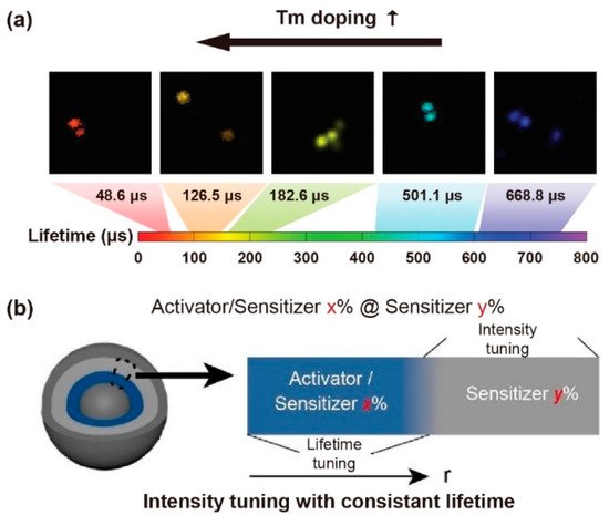
Figure 3. (a) The time-resolved confocal images of NaYF4: Yb,Tm nanoparticles and the lifetime tuning scheme by changing Tm3+ doping concentrations. Reproduced with permission from [20]. Copyright 2014, Nature Publishing Group. (b) Diagrammatic illustration of consistent lifetime with tunable intensity by doping various sensitive gradients in the shell. Reproduced with permission from [47]. Copyright 2021, WILEY-VCH.
2.3. Adjusting the Energy Transfer Channel
The decay process of an excited state is inversely proportional to the energy transfer rate and the radiative and non-radiative transition rates. Tri-doped nanoparticles of NaYF4@NaYF4: Er3+/Yb3+/Mn2+@NaYF4 were synthesized by Mao et al., exhibiting the new energy transfer process between Mn2+ and Er3+. With a non-radiative energy transfer channel created between the level of Mn2+ (4T1) and Er3+ (2H11/2 and 4S3/2), the overall transition rate increased owing to the resonance energy transfer, leading to a reduced lifetime of Er3+ at 550 nm. The presence of Mn2+ ions promoted the relaxation of the 4S3/2 energy level, and the red emission of Er3+ increased with the shortening of the decay time. Therefore, the increased population density of Mn2+ caused the decreased radiative transition rate of Er3+ (4S3/2 and 2H11/2) turning down to ground state, resulting in an enhancement of red emission due to energy transfer from Mn2+ (4T1) to Er3+ (4F9/2) (Figure 4a). Meanwhile, the increased lifetime of Er3+ at 650 nm also verified the role of Mn2+ in energy transfer trace according to the decay curves of various content of Mn2+(0%, 10%, 20%, 30%) (Figure 4b) [34].
Introducing transition metal ions with a long lifetime into conventional UCNPs is particularly attractive. The lifetime of Mn2+ ions could be modulated by crystal-site engineering. Liu et al. tuned the luminescence properties of Mn2+ in core–multishell nanoparticles by doping Ca2+ or Mg2+, changing the output color from green to yellow and prolonging its lifetime [49]. The spin-forbidden transition of Mn2+ occurs between 4T1→6A1, allowing a longer fluorescence lifetime than lanthanide emitters. Because of the larger energy mismatch between Yb3+ and Mn2+, the Yb3+-Mn2+ dimer is difficult to form. However, Zhang et al. reported the successful preparation of Yb3+-Mn2+ dimers, obtaining a substantial long lifetime of Eu3+ (91 ms), while the normal UC lifetime of Eu3+ is only about 7 ms. In addition, there is a dynamic population balance between the energy state |2F7/2,4T1(4G)⟩(Yb3+–Mn2+ dimers) and 5D0 (Eu3+), causing the sustained energy transferring from Yb3+–Mn2+ dimers to Eu3+ [50].
The long-lived Mn2+ integrated with the short-lived lanthanide particle platform could establish a new energy transfer pathway, and then affect the whole decay process. In a NaGdF4: 30%Mn@NaGdF4: 49%Yb,1%Tm@NaYF4 nanoparticle, Gd sublattice-mediated energy migration facilitates Mn2+ upconversion luminescence, leading to a decrease in the lifetime of Gd3+ at 311 nm (6P7/2→8S7/2) from 6.5 to 4 ms (Figure 4c) [51]. As a result, the lifetime of lanthanide ions may be affected when the external ions introduced and interfered with the energy transfer channels.
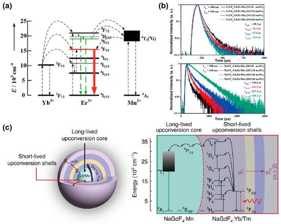
Figure 4. (a) The diagram for energy transfer mechanism among Yb3+, Er3+ and Mn2+ under 980 nm excitation. (b) Luminescence decay curves of Er3+ at 550 nm and 650 nm in NaYF4: Yb3+/Er3+ nanoparticles with different Mn2+ concentrations (0, 10, 20 and 30 mol%). Reproduced with permission from [34]. Copyright 2016, Royal Society of Chemistry. (c) Structural design of core–multishell nanoparticle and the energy transfer pathway among the Yb3+, Tm3+, Gd3+ and Mn2+ ions for the short- and long-lived upconversion luminescence under 980 nm excitation. Reproduced with permission from [51]. Copyright 2017, Nature Publishing Group.
Doping various amounts of Gd3+ into the NaYF4 host nanocrystals could regulate the upconversion photoluminescence lifetimes. Xie et al. prolonged the lifetime of Er3+ (4S3/2→4I15/2, 4F9/2→4I15/2) by utilizing the Gd3+, substituting for Y3+ and Yb3+ in the crystal lattice of NaYF4 host, which attributed to the energy transfer rate decrease caused by the average sensitizer-activator separation increasing [52].
2.4. Fluorescence Resonance Energy Transfer
An efficient energy transfer pathway could be established in fluorescence dye-loaded rare-earth nanocrystals, which enables luminescence lifetime tuning [53]. In contrast to conventional molecular donor–acceptor pairs, the energy transfer efficiency is related to the distances between lanthanide-doped nanoparticles, and thus significantly depends on the nanoparticle diameter. Hirsch et al. synthesized NaYF4: 20%Yb,2%Er with the precisely controlled size spanning from 10 to 43 nm, and coated with sulforhodamine B and rose bengal by ligand exchange. The nanoparticles with a mean diameter ranging from 20 to 25 nm possessed an optimum efficiency of 50–60%. The lifetime of Er3+ at 600 nm decreased primarily due to the competition of non-radiative surface deactivation at the smaller surface-to-volume ratios (Figure 5a) [54]. Li et al. loaded the IR-820 on NaYF4: Tm to construct a FRET system. Luminescence decay from 3H6→3H4 transition was used as a detection signal. When the energy accepter (IR-820) was attached to the donor (Tm3+: 3H4) under 785 nm excitation, the lifetime of Tm3+ at 800 nm decreased because of luminescence resonance energy transfer (Figure 5b) [55]. Su et al. loaded the IR-806 on the NaGdF4: 49%Yb,1%Tm@NaYF4: 20%Yb@NaGdF4: 50%Nd,10%Yb@NaGdF4 nanoparticles to improve the ultraviolet luminescence intensity. With the back energy transferred from the nanoparticles to dye molecules, the decreased lifetimes of Gd3+ and Tm3+ ions were observed at 253, 276, 290, 310, 360 and 475 nm [56]. An organic fluorescent dye as an antenna could be used to broaden and increase absorption for UCNPs, allowing the energy to flow to dye molecules. Meanwhile, the hybrid system between dye molecules and UCNPs creates a new energy diffusion pathway, increasing the radiative transition process. Li et al. added the Cy3-SO3 into a NaYF4: 20%Yb,2%Er@CaF2 solution to construct an energy dissipation channel, which could transfer energy to the dye by the radiative transition. As a result, the luminescence lifetime of Er3+ at 488 nm decreased with the concentration of Cy3-SO3 increase (0.67, 2, 4, and 5.33 μM). The reduced lifetime value verified the non-radiative energy transfer process between Er3+ and Cy3-SO3 [57].
The triplet excitons could be trapped by inter- or intra-molecular interactions and prolong organic phosphorescence. For example, Yb3+ luminescence could be generated by organic Yb3+ complexes and hybrid organic-conjugated Yb3+-doped nanoparticles. Ye et al. prepared a composite thin film, in which the Yb3+ ions are incorporated with tetrakis-(pentafluorophenyl)imidodiphosphinate to form the Yb(F-TPIP)3 chelate, while zinc salt of 2-(tetrafluoro-2-hydroxyphenyl)tetrafluorobenzothiazole (Zn(F-BTZ)2) served as the organic chromophore. The Zn(F-BTZ)2 possessed the emission ranging from 450 nm to 900 nm under 405 nm excitation, and gave rise of the Yb3+ emission centered at 975 nm from the transition of Yb3+: 2F5/2→2F7/2. Note that the intrinsic lifetime of Yb3+ at 1 μm is about ~1 ms. The lifetime of sensitized organic Yb3+ compounds could prolong up to ~0.3 s. The prolonged emission lifetime was demonstrated by dynamic equilibrium due to the energy transfer process from long-lived organic triplet excitons [58].
The surface ligand coordination could reconstruct the crystal-field splitting and orbital hybridization, and narrow the gap of the 4d orbitals between inner and surface lanthanide sensitizers. For example, after the bidentate picolinic acid (2PA) molecules coordinated to NaGdF4: Yb nanoparticles, a longer lifetime (289 μs) at 980 nm was observed. The results confirmed that 2PA molecules could activate the dark surface layers and facilitate energy migration in the Yb3+ sublattices. The Yb3+-2PA coupling facilitated energy migration by 4f-orbital energy resonance within the ytterbium sublattice, which can reduce surface defects to hinder energy diffusion. Density functional theory (DFT) verified that 2PA coating could narrow the gap between the superficial and inner Yb3+ by lowering the empty 4f levels. Rigid ligands also stabilized the excited state of superficial Yb3+, prevented the superficial lanthanide ions from the solvent and fluoride vacancy-induced quenching, and thus significantly suppressing multiphonon non-radiative decay (Figure 5c) [59].
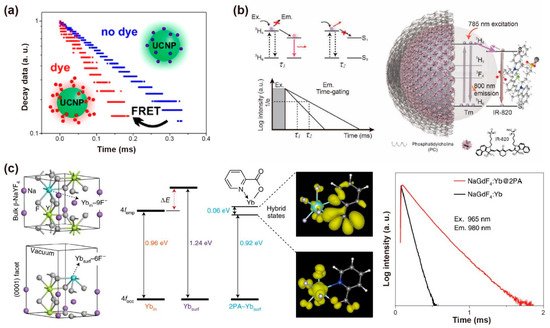
Figure 5. (a) Schematic diagram of the lifetime changing due to the existence of FRET process from UCNPs to dye molecules. Reproduced with permission from [54]. Copyright 2017, American Chemical Society. (b) Schematic representation of the structure of the NaYF4: Tm@PC-IR-820 nanocomposites, the absorbance and emission in the same transition (3H6–3H4) of NaYF4: Tm nanoparticles and the variation of lifetime affected by the amount of IR-820 dye molecules. Reproduced with permission from [55]. Copyright 2019, WILEY-VCH. (c) The optimized structure shows ytterbium atoms located in the interior (Ybin) and exterior (Ybsurf) position, the simulated 4f energy levels of ytterbium atoms, the spatial distribution of the charge densities for coupling states and the lifetime decay curves of Yb3+ at 980 nm with and without 2PA capping on the NaGdF4: 5%Yb nanoparticles (10 nm) excited at 965 nm. Reproduced with permission from [59]. Copyright 2021, Nature Publishing Group.
2.5. Changing Temperature
The synthesized process would affect the crystallinity, phase state and volume of nanoparticles and thus influence the decay behaviors. Vatsa et al. studied the decay process of GdVO4: Dy3+ nanoparticles after heat treatment. When heated from 500 °C to 900 °C, the lifetime of Dy3+ (4F9/2 level) extended from 114 μs to 260 μs due to the reduction of the non-radiative process by surface inhomogeneities. This increase in lifetime can also be ascribed to the decrease in the surface defects with the particle size increases in the heat treatment process (Figure 6a) [60]. For YVO4: Ln3+ (Ln3+ = Dy3+, Eu3+) nanoparticles, the increase in covalent bond interaction caused by heat treatment led to a red shift in V–O charge transfer (CT). Similarly, the lifetimes of Dy3+ at 4F9/2 and Eu3+ at 5D0 increase with temperature from 500 °C to 900 °C due to the reduction of the non-radiative process on the surface of the particles [61].
As is well known, the decay time constant is inversely proportional to the radiative and non-radiative transition rates in the cross-relaxation process. The luminescence lifetime decreases with the increase of ambient temperature in most cases. The decay time with specific emissions produced by radiative transition rarely varies with temperature, while the non-radiative decay rate changes significantly with temperature [62]. For example, the lifetime of Yb3+ at 1000 nm reduced from 470 ± 11 μs to 390 ± 12 μs in NaYF4: Nd3+, Yb3+ nanoparticles as the temperature rose from 25 °C to 45 °C. While the thermal coefficient ατ calculated by the TGI system was almost unchanged (−0.0092~−0.010 °C−1) (Figure 6b,e) [63]. Moreover, cross-relaxation between Tm3+ (1G4) usually occurs when raising the emitter concentration or temperature. Yu et al. compared the sensitivity of β-PbF2: Tm3+/Yb3+ with different Tm3+ doping concentrations. They found that the relative sensitivity maximum values of 1G4 state lifetime in 0.0005Tm, 0.01Tm and 0.05Tm nanoparticles are 0.16%K−1, 0.26%K−1 and 0.46%K−1 at 488K, respectively, indicating the potential ability as an indicator of upconversion luminescence lifetime-based thermometer [64].
In addition, the host matrix has a significant effect on thermal sensitivity. Díaz et al. found that oxide materials are more sensitive than fluoride ones by comparing the decay curves of NaYF4: Er,Yb and NaY2F5O: Er,Yb nanoparticles at room temperature and 60 °C. [65]. The temperature dependency of Yb3+ emission lifetime in NaYF4@NaYF4: Yb3+,Nd3+@CaF2 nanoparticles was determined by the energy transfer and back energy transfer rate, the energy migration process (among Yb3+), as well as radiative and non-radiative transition. Both the concentration of Nd3+ and Yb3+ affected the temperature sensitivity by changing the distance of Yb3+-Yb3+ and Yb3+-Nd3+, which in turn affected the back energy transfer processes from Yb3+ to Nd3+ and energy migration between Yb3+ ions. NaYF4@NaYF4: 20%Yb3+,60%Nd3+@CaF2 as the nanoprobe possessed optimum thermal sensitivity through varying doping concentrations of Yb3+ and Nd3+, in which the lifetime of Yb3+ at 980 nm descended from 898 μs to 450 μs when the temperature increased from 10 °C to 64 °C. (Figure 6c,f) [66].
Interestingly, Li et al. demonstrate the lifetime compensation with temperature in NaErF4@NaGdF4 core–shell nanoparticles. The temperature-independent lifetime is attributed to the balance between lattice expansion (prolonging the lifetime) and thermal quenching (shortening the lifetime). A considerable energy migration process occurs in the high-doping concentration of Er3+, and the efficiency is proportional inversely to the average donor-acceptor distance with sixth order of magnitude. As a consequence, elevated temperature induces the lattice to expand, leading to a longer transfer distance, and ultimately prolonging the lifetime of Er3+. However, the prolonged lifetime caused by lattice expansion compensated for the difference value of the shorter lifetime aroused by thermal quenching, resulting in the temperature-independent lifetime (Figure 6d) [67].
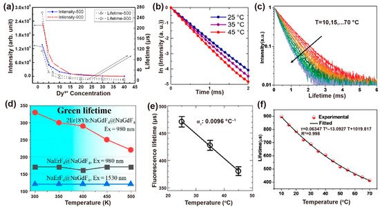
Figure 6. (a) Intensity (left) and the corresponding decay lifetime of Dy3+ at 4F9/2 states (right) with the dependent variable of Dy3+ concentration when excited at 310 nm. Reproduced with permission from [60]. Copyright 2009, AIP Publishing. (b) Luminescence decay curves of NaYF4: Nd3+,Yb3+ at different experimental temperatures and (e) the corresponding calibration curve of temperature vs. luminescence lifetime. Reproduced with permission from [63]. Copyright 2019, Nature Publishing Group. (c) The decay curves of the measured NaYF4@NaYF4: 20%Yb3+,60%Nd3+@CaF2 nanoprobe at various temperatures and (f) corresponding nonlinear fitted curves between measured lifetime and temperature ranging from 10 °C to 70 °C. Reproduced with permission from [66]. Copyright 2020, WILEY-VCH. (d) Negative correlation curves of the lifetime of Er3+ at 4S3/2 versus ambient temperature for NaErF4@NaGdF4 and NaErF4: 18%Yb,2%Er@NaGdF4 nanoparticles. Reproduced with permission from [67]. Copyright 2020, MDPI.
This entry is adapted from the peer-reviewed paper 10.3390/bios12020131
This entry is offline, you can click here to edit this entry!