One of the prominent problems faced with hydro-dominant power system is ultra-low-frequency oscillation (ULFO) with a frequency deviation of 0.1 Hz lower, which is caused by the negative damping of hydro generators. ULFO might lead to an oscillation of all generators with the same oscillation frequency, restricting consumption of hydropower renewable energy.
- Ultra-Low-Frequency Oscillation (ULFO)
Dear author, the following contents are excerpts from your papers. They are editable.
(Due to the lack of relevant professional knowledge, our editors cannot complete a complete entry by summarizing your paper, so if you are interested in this work. you may need to write some contents by yourself. A good entry will better present your ideas, research and results to other scholars. Readers will also be able to access your paper directly through entries.)
1. Introduction
The ULFO phenomenon has been observed in power systems all over the world. In a Turkish power system, oscillations with frequency deviation of about 0.05 Hz were observed [5]. In 2008, the ULFO occurred in Colombia power grid when the proportion of hydropower was increased [6], and the oscillation lasts about 20 s. In 2012, there was an abnormal frequency fluctuation in JinSu DC Island test in China, with a period of about 14 s and an amplitude of ±0.26 Hz [7]. On 23 January 2015, there was an ULFO with an oscillation period of 13 s and an oscillation frequency of about 0.08 Hz, lasting for about 4 min. After the trip of the Tibetan Wooden unit, the frequency of the Tibetan middle power grid exceeded the low-frequency load-shedding limit [8]. In the 2016 asynchronous networking test of Yunnan power grid (YNPG), long-term and large-amplitude ULFO also occurred with an oscillation period of about 20 s and an amplitude of ±0.1 Hz lasting for nearly half an hour. It posed a major threat to the safe and stable operation of YNPG after asynchronization [9]. The asynchronous operation of the Southwest China Power Grid (SCPG) faced with an obvious risk of ULFO according to the simulation. The governor parameters optimization [10] and the DC frequency limit control (FLC) are adopted to suppress it. The asynchronous operation test of SCPG verifies the effectiveness of the strategy.
In fact, the ULFO is not a new problem in the power system. In the early stage of the power system development, there are cases of ULFO in the local power grid with isolated load or dominated by hydropower. P Kundur discovered this problem as early as the 1970s and 1980s and analyzed it. It was pointed out that an over-fast adjustment of the speed control system will produce negative damping within the ultra-low-frequency band, so it is necessary to carefully adjust the governor parameters [11,12]. However, with the development of thermal power and the synchronous interconnection of power grid, the ULFO has not been the focus of academic and industrial circles for a long time. No research or technical reserve has been built. When the ULFO occured in the asynchronous operation test of YNPG, the dispatchers had no clear means to quell the oscillation, so they could only try to find the effective control method by trial and error [13].
With the continuous occurrence of ULFO events, the mechanism, characteristics and control strategy of ULFO have become a research hotspot. In terms of mechanism and characteristics, the relevant research mainly analyzes the causes and main influencing factors from the aspects of eigenvalue analysis [14], parameter sensitivity [15,16] and damping torque coefficient [17,18]. In terms of control strategy, the research mainly focuses on the means of governor parameter optimization and adjustment [7,19,20], introduction of frequency limit control (FLC) of HVDC [21,22], and the means of optimizing PSS parameters or using governor additional control [23,24] to suppress ULFO, but it has not yet been applied.
For the hydropower grid that SCPG and YNPG represent, there is no clear standard or requirement for the level to which the ULFO damping needs to be raised when formulating the ULFO suppression strategy. As the ULFO period is distinctly longer than the low-frequency oscillation, the existing low-frequency oscillation dynamic damping control index can not be directly adopted as the guide of the ULFO control. The lack of guiding foundation for the oscillation analysis in the operation of a practical power system requires for a specific index, based on which the control strategy and the damping control are designed. Simulation analysis has shown that the range and strategy of governor parameter optimization and adjustment are significantly different according to different damping control indexs.
2. Mechanism and Control Strategy of ULFO in Hydropower Dominant Power Grid
2.1. The Inevitability of the ULFO in Hydropower Dominant Power Grid
The open-loop system model of a governor and a turbine can be expressed in Figure 1. The model of the most commonly used governor and turbine are detailed in the Appendix A.
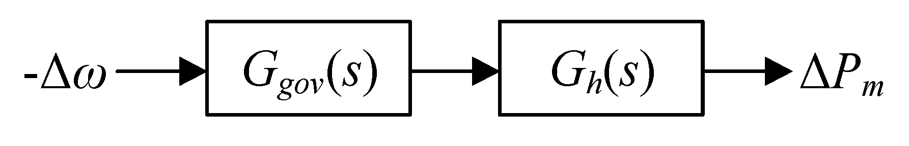
The open-loop transfer function of the governor and turbine system in Figure 1 can be expressed as:

Decomposing (3) in the Δδ–Δω coordinate system, mechanical power deviations of a governor can be expressed in terms of its speed ω and angle δ deviations, known as damping and synchronizing torque, respectively [25].
where (p.u./rad/sec) and (p.u.) are damping and synchronizing coefficients, respectively.
With the open-loop transfer function of hydro turbine governor, the damping coefficient at frequency f is obtained by substituting the Lagrange operator into (6). The physical meaning of is that it is the projection of mechanical torque on the axis, indicating the magnitude of the damping torque. When > 0, the turbine governing system provides positive damping to the system.
With the typical parameters, the governing system of the hydropower unit provides negative damping in the ultra-low-frequency range, as shown in Figure 2.
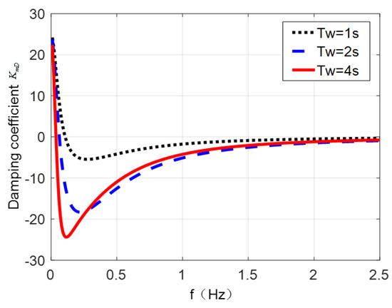
Figure 2 illustrates that as the water starting time Tw increases, the damping coefficient is of large negative values in the ultra-low-frequency band of [0–0.1] Hz. The water starting time Tw usually varies with different load, penstock and hydraulic head. However, regardless of Tw values, the damping coefficients are always negative, which means the damping of whole system increases with the primary frequency regulation system being taken out [26].
2.2. Analysis of Influencing Factors
The influence of key parameters such as time constant of water hammer effect and PID parameter of governor on ULFO has been analyzed in detail by root locus, parameter sensitivity and other methods [9,10,11,12,13]. The simulation text further shows that the damping and amplitude of the ULFO are closely related to the disturbance form, unit parameters and operation mode of the power grid. This section takes an actual power system of sending plant as an example to build a single power plant with load model, as shown in Figure 3. The generator G1–G4 adopts a typical 8-type governor model and parameters according to field tests. The N-1 fault at transmission line can excites ULFO. This section analyzes the generator inertia time constant, the governor frequency input limit in the governor model and the output limit of water turbine to further clarify their influence on amplitude of ULFO.
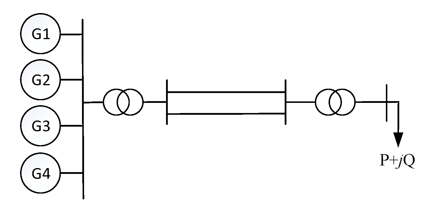
Figure 3. Single power plant with load system.
2.2.1. Inertia Time Constant
Set the inertia time constant Tj to be two times and a half of the original value respectively. Simulation results considering different Tjs are shown in Figure 4. It can be seen that at the beginning of the fault, the oscillation is of negative damping. After that, it becomes to equal amplitude oscillation. The larger Tj is, the smaller the amplitude of ULFO becomes.
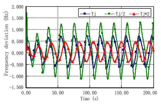
Figure 4. Frequency oscillations under different Tj values.
2.2.2. Governor frequency input limiting
The frequency input limitation shown in Figure A1 is used to restrict the input frequency deviation and ensure the safety of turbine unit. Set the governor frequency input limiting Max/Min to be ± 0.1, ± 0.15, and ± 0.2 Hz, respectively; the simulation results are shown in Figure 5. It can be seen that at the beginning of the fault, the amplitude oscillation still appears, and then it turns to equal amplitude oscillation, and the higher the frequency input limit, the greater the amplitude of ULFO.
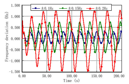
Figure 5. Frequency oscillations under different MAX/MIN values.
2.2.3. Mechanical Power Output Limiting
The output limitation shown in Figure A2 is used to restrict the output of hydroturbine. Set the water turbine output limiting Pmax (unit value) to be 1.01, 1.05 and 1.1, respectively; the simulation results are shown in Figure 6. It can be seen that the higher the frequency output limiting, the higher the governor’s participation in the ULFO, and the greater the amplitude of the ULFO.
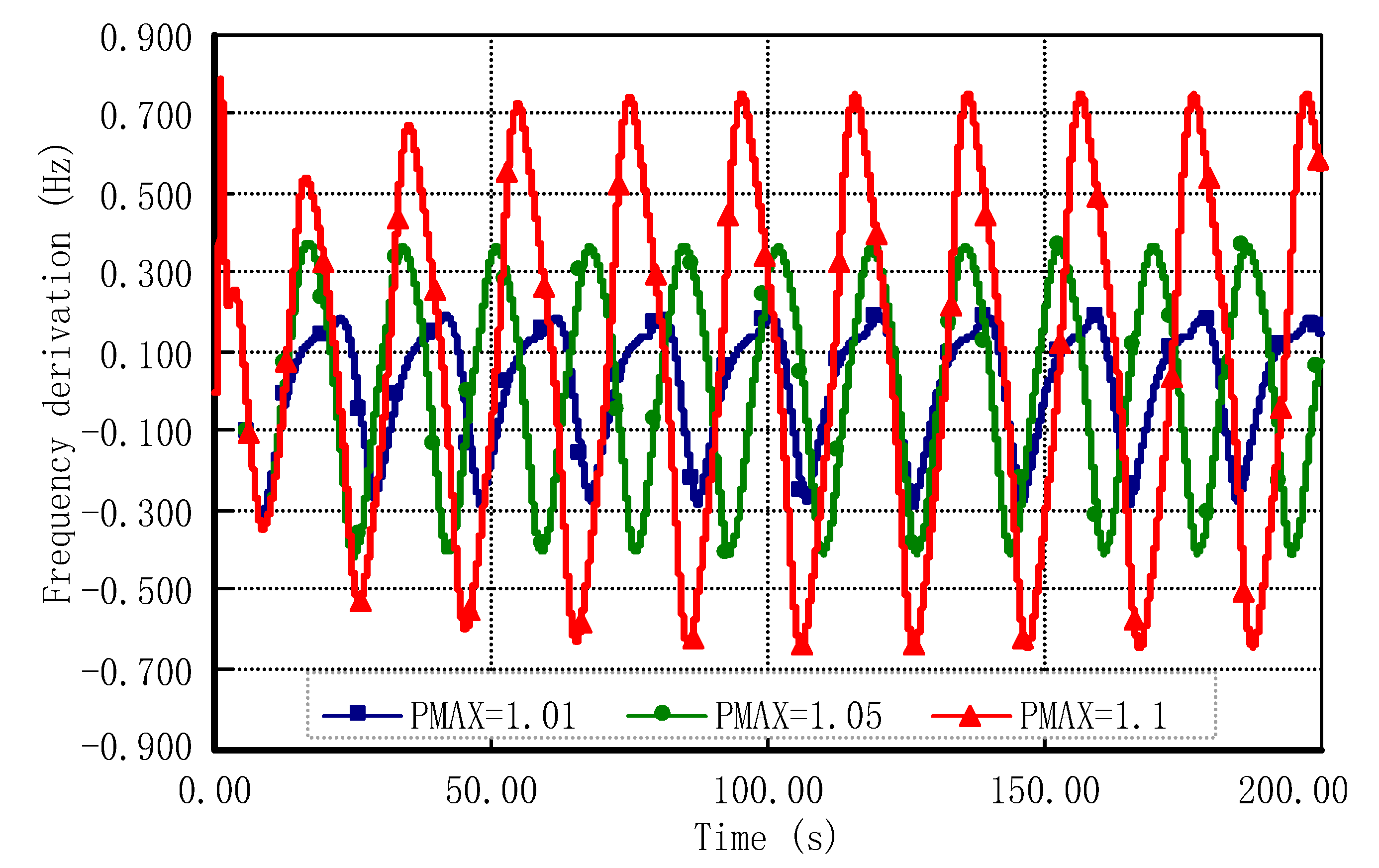
Figure 6. Frequency oscillations under different Pmax values.
2.3. Control Measures of ULFOs in Hydro-Dominant Power Systems
There are three ways to control the ULFO in hydro-dominant power systems:
(1) From a perspective of increasing the positive damping level of the system, adjusting the operation mode and increasing the capacity of the thermal power, which provies positive damping on ULFOs, can be adopted. The advantage is that it does not affect the frequency regulation capacity of the power grid. However, increasing the thermal power is not conducive to the consumption of sustainability hydropower energy. The feasibility is relatively low under the current situation, which requires energy conservation, emission reduction and a large amount of clean energy.
(2) From a perspective of reducing the negative damping provided by the hydropower unit, the PID parameters optimization of the governor of hydro unitcan be adopted. The advantage of this method is that the ULFO can be damped without affecting the operation mode of power system. However, the optimization of governor parameters usually leads to weaken the system frequency regulation ability. Therefore, it is necessary to achieve a balance between suppressing the ULFO and maintaining the frequency regulation ability.
(3) In addition, the positive damping also can be increased by using HVDC modulation, such as FLC. The advantage by using FLC is that it canstrengthen the frequency modulation ability of system. However, due to the limited number of HVDC, the control measures will be greatly weakend when HVDC maintenance or shutdown because of contingency.
In general, the parameter optimization of governors is the most common and effective method in a practical power system. For regional or provincial power grids dominated by hydropower, such as the SCPG and YNPG, there are many types of hydropower units in the grid so that it is impossible and unnecessary to optimize and adjust the governor parameters for all. However, it requires for a clear control index or damping ratio standard to follow in the formulation of the ULFO suppression strategy. The appropriate range of governor parameter optimization should be verifiable.
This entry is adapted from the peer-reviewed paper 10.3390/su12187316