There are significant levels of concern about both the safety assessment and financial evaluation of the whole hydropower system, especially at early project stages. In addition, there is a variety of reliable and accurate methods for analysis, design, and optimization of steel pressure liners in hydropower plants. Several countries have developed specific regulations and codes for the design, installation, and safety evaluation of under-pressure piping, as well as estimates of the potential risks associated with failure. This article reviews the current methodologies and codes available for design and safety assessment of either unstiffened or stiffened pressure steel liners in hydropower plants.
- steel liner
- penstock design
- buckling failure
- liner instability
- pressure pipelines
1. Introduction
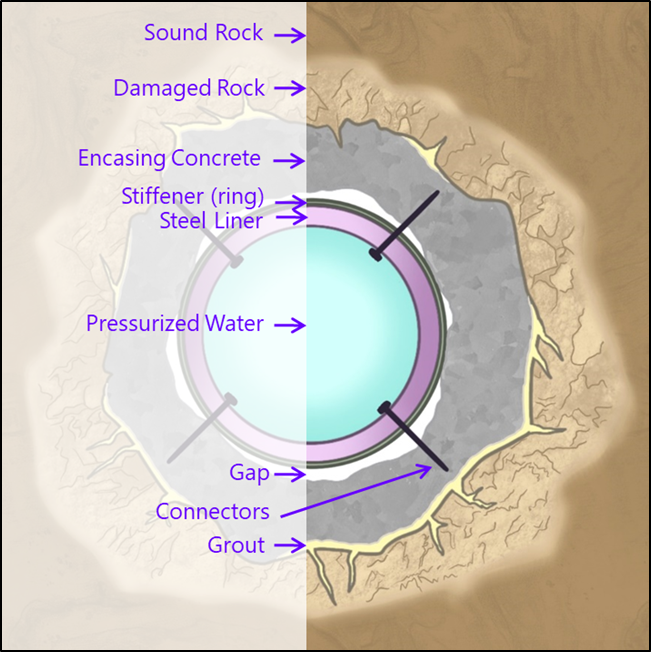
-
Steel pressure liner that conveys water under pressure.
-
Reinforced or mass-concrete backfill that encases the steel liner.
-
An existing gap between the steel liner and the surrounding concrete.
-
Grouted rock (if any) for either waterproofing or improvement of the terrain.
-
Damaged rock that remains in place after blasting or excavation. The values of the outer radius of such zone may range between one and five times that of the piping. An estimate of the thickness of fissured rock may be from 0.3 to 1 m with the use of a tunnel borer and 1–2 m with blasting [4].
-
Sound rock, usually assumed to be uniform, isotropic and elastic with a deformation modulus Er.
-
Stiffeners that are attached to increase the moment of inertia of the pipe wall.
-
Steel connectors anchored in concrete.
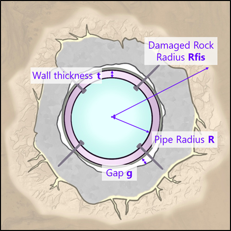 (a)
(a)
|
Main variables |
||
|
R |
Liner Radius1 |
Average value between the external and internal radius |
|
D |
Diameter |
D = 2·R |
|
t |
Wall thickness of the liner |
|
|
I |
Moment of inertia of the stiffeners |
|
|
g |
Gap |
|
|
L |
Span length between stiffeners |
|
|
Rfis |
Radius of the fissured rock |
|
|
Ec |
Moduli of elasticity of the concrete backfill |
|
|
Es |
Moduli of elasticity of the steel |
|
|
E’ |
Moduli of elasticity of the steel under plane strain assumption |
|
|
fsy |
Yield stress of the steel |
|
|
Ps |
Internal pressure absorbed by the steel liner |
|
|
Pcr |
Critical Buckling Pressure |
|
|
ν |
Poisson's ratio |
|
|
n |
Number of lobes formed in a stiffened liner. It also indicates the buckling failure mode |
|
1 Also expressed as Rs by many authors.
|
Parameter |
Range |
|
D/t |
100 – 400 |
|
L/t |
60 – 240 |
|
g/R |
0.0003– 0.001 |
3. Types of Steel Liners
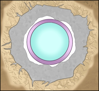
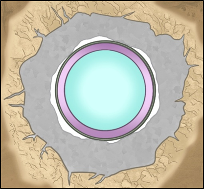
3. Unstiffened Liners
-
Its outer diameter is smaller than that of a steel casing with stiffeners, by which the tunnel excavation diameter will be smaller.
-
Implementation is simpler, especially for wall thicknesses less than 30 mm. For greater values, welds may be more complex and entail a higher financial cost.
4. Stiffened Liners
-
They provide the steel cylinder with greater rigidity and, depending on their shape, may bind the sheet steel to the concrete (thus behaving as connectors).
-
Due to their greater moment of inertia, they are lighter than a liner with the same resistance capacity.
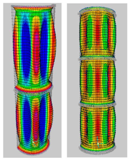
5. Regulations and Codes regarding Steel Liners Design
The most known codes are:
- The CECT issued a regulation[8] that explicitly makes reference to calculation of steel liners. It includes equations and nomograms derived from the Amstutz formulation and requires a safety factor greater than 1.6.
- The USACE Code [10] recommends the methods provided by Amstutz, Jacobsen and Vaughan with regard to overall instability. For analysis of local buckling of the span between stiffeners it recommends the formulations of von Mises and Donnell. Indeed, design is considered to be acceptable when the calculated stresses do not exceed 80% of the yield stress.
Other related codes are the following:
- The Boiler and Pressure Vessel Code (2001), provided by the American Society of Mechanical Engineers (ASME).
- The Technical Guide on Pipelines for the Transport of Pressurised Water, provided by the Centre for Studies and Experimentation in Public Works: (Centro de Estudios y Experimentación de Obras Públicas, CEDEX, Spain), that gathers an extensive range of Standards associated with calculation methods in pressurised water tunnels (based on the American Water Works Association Manual M11).
- ASTM F1216 (1998), published by the American Society for Testing and Materials (ASTM). [11]
- The Recommended Practice DNV-RP-C202 for the Buckling Strength of Shells, published by Det Norske Veritas. [12]
- Buckling of Steel Shells: European Recommendations, provided by the European Convention for Constructional Steelwork (ECCS).[13]
- Design Guidelines for Pressure Tunnels and Shafts AP-5273, provided by the Electric Power Research Institute (EPRI). [4]
However, design guidelines for the application of high-strength steel for steel liners are still missing [14]. For that Pachaud et al. [15] [16][17] have proposed methodology for safety assessment of the steel liners of pressure tunnels and shafts, specially motivated for the weakness that welding imperfections may affect the liners.
This entry is adapted from the peer-reviewed paper 10.3390/app12031072
References
- Brekke, T. L.; Ripley, B. D. Design Guidelines for Pressure Tunnels and Shafts; Berkeley, 1987
- Araceli Martin-Candilejo; José L. G. Valdeolivas; Alfredo Granados; Juan C. Mosquera Feijoo; A Comparative Review of the Current Methods of Analysis and Design of Stiffened and Unstiffened Steel Liners. Applied Sciences 2022, 12, 1072, 10.3390/app12031072.
- J. L. G. Valdeolivas; J. C. Mosquera; A Full 3D Finite Element Model for Buckling Analysis of Stiffened Steel Liners in Hydroelectric Pressure Tunnels. Journal of Pressure Vessel Technology 2013, 135, 061205, 10.1115/1.4024445.
- Brekke, T.L.; Ripley, B.D. Design Guidelines for Pressure Tunnels and Shafts; University of California: Berkeley, CA, USA, 1987
- Wang, Z.; Du, K.; Xie, Y.; Su, X.; Shi, Y.; Li, X.; Liu, T. Buckling Analysis of an Innovative Type of Steel-Concrete Composite Support in Tunnels. J. Constr. Steel Res. 2021, 179, 106503.
- Gao, B.; Yin, Z.; Zhao, F.; Shang, C. A Temporary Local Rigid Clamping Structure to Improve Antibuckling Ability of the Thin-Walled Cylinder under External Pressure. J. Press. Vessel Technol. Trans. ASME 2018, 140, 4
- Berti, D.; Stutzman, R.; Lindquist, E.; Eshghipour, M. Buckling of Steel Tunnel Liner under External Pressure. J. Energy Eng. 1998, 124, 55–89
- Comité Européen de la Chaudronnerie et de la Tolerie (C.E.C.T.). Recommendations for the Design, Manufacture and Erection of Steel Penstocks of Welded Construction for Hydro Electric Installations; European Committee of Boiler, Vessel and Pipe Work Manufacturers: Paris, France, 1979.
- Omara, A.M.; Guice, L.K.; Straughan, W.T.; Akl, F.A. Buckling Models of Thin Circular Pipes Encased in Rigid Cavity. J. Eng. Mech. 1997, 123, 1294–1301
- U.S. Army Corps of Engineers (USACE). Engineering and Design. Tunnels and Shafts in Rock; U.S. Army Corps of Engineers (USACE): Washington, DC, USA, 1997.
- American Society for Testing and Materials (ASTM). Standard Practice for Rehabilitation of Existing Pipelines and Conduits by the Inversion and Curing of a Resin-Impregnated Tube (F1216-16); Appendix X1; ASTM: West Conshohocken, PA, USA, 2016.
- Det Norske Veritas (DNV). Buckling Strength of Shells. Recommended practice DNV-RPC202; Det Norske Veritas (DNV): Høvik, Norway, 2002
- Rotter, J.M.; Schmidt, H. (Eds.) Buckling of Steel Shells European Design Recommendations, 5th ed.; European Convention for Constructional Steelwork (ECCS): Edinburgh, UK, 2013.
- Schleiss, A.; Pachoud, A.J. Influence of Geometrical Imperfections and Flaws at Welds of Steel Liners on Fatigue Behavior of Pressure Tunnels and Shafts in Anisotropic Rock; EPFL-LCH: Lausanne, Switzerland, 2017.
- Pachoud, A.J.; Manso, P.A.; Schleiss, A.J. New Methodology for Safety Assessment of Steel-Lined Pressure Shafts Using High-Strength Steel. Int. J. Hydropower Dams 2017, 24, 80–88.
- Pachoud, A.J.; Manso, P.A.; Schleiss, A.J. New Parametric Equations to Estimate Notch Stress Concentration Factors at Butt Welded Joints Modeling the Weld Profile with Splines. Eng. Fail. Anal. 2017, 72, 11–24
- Pachoud, A.J.; Berthod, R.; Manso, P.; Schleiss, A. Advanced Models for Stress Evaluation and Safety Assessment in Steel-Lined Pressure Tunnels. Hydropower Dams 2018, 25, 77–82
