Your browser does not fully support modern features. Please upgrade for a smoother experience.
Please note this is an old version of this entry, which may differ significantly from the current revision.
Subjects:
Engineering, Electrical & Electronic
Unmanned aerial vehicles (UAVs) have become an essential component in many wireless communication systems because of their rapid deployment, mobility, and flexibility.
- UAV network
- tethered UAVs
- placement algorithms
1. Introduction
Unmanned aerial vehicles (UAVs) have become an essential component in many wireless communication systems because of their rapid deployment, mobility, and flexibility [1]. In cellular communication networks, UAVs can act as aerial base stations by mounting mobile base stations on them [2]. However, the practical limitations of UAVs prevented them from being used as a replacement for the cellular base station. These limitations include available UAV payload, endurance, and onboard available processing energy. In order to use the UAV as an aerial base station, it is required to equip the UAV with processing units and antennas. The currently UAV-available payloads are very limited. In order to increase the payload of a UAV, a stable source of energy is required, which is not available in UAVs. UAV’s limited flying time is one of the obstacles to utilizing UAVs’ BS. The UAV needs to be grounded to recharge or change the battery, which reduces the performance of the communication network. In addition, providing the required power for processing and communication using the UAV battery is a challenge. Therefore, a permanent power source for UAV is required to achieve a reliable aerial base station that can be provided using tethered UAVs (TUAVs) [3]. A TUAV is a UAV supplied by both power and data over a cable from a ground station (GS), as shown in Figure 1. The specifications of TUAVs implemented by many companies are summarized in [4]. It shows that TUAVs can fly from 10 h to an unlimited amount of time. On the other hand, TUAV has a main drawback, the limited tether length, which restricts their mobility and placement flexibility. Comparing TUAVs with cellular BSs and UAVs, TUAVs can achieve the main requirements of a reliable cellular BS in terms of endurance, backhaul link quality, and the advantage of the UAV’s high altitude, as shown in Figure 2. Recently, AT&T deployed the first TUAV to provide cellular coverage in Puerto Rico for the affected regions after Hurricane Maria [5], which means that, TUAV can be a realistic alternative to a cellular BS. To this end, we introduce TUAV as a viable alternative to replace BS. Then, we propose a new relay system that uses a UAV as a relay station between a TUAV and a ground user (TU2U2G) TU2U2G system. Then, the 3D placement of the UAV as a relay station is presented. We formulate the optimization problem to maximize UAV relay station coverage under the power budget and maximum UAV height constraints.
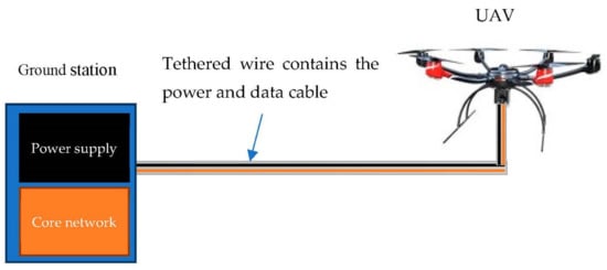
Figure 1. TUAV station components.
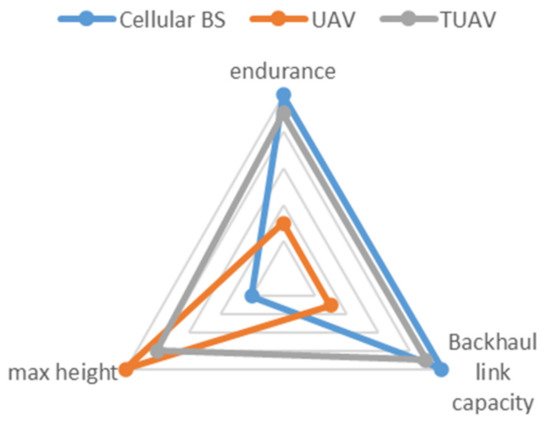
Figure 2. Cellular BS versus UAV versus TUAV.
1.1. Related Work
Several pieces of research were presented on the placement of UAVs. In [6,7,8,9,10], the placement of UAVs for coverage maximization was proposed. Authors in [6] proposed an algorithm that jointly optimizes the 3D UAV placement and path loss compensation factor to maximize the user coverage in the uplink transmission. An approach to minimize the total transmit power required to provide wireless coverage for indoor users was presented in [7]. A placement algorithm that maximizes the number of covered users with minimum transmission power was proposed in [8]. The UAV placement that maximizes the number of served users with different quality-of-service requirements was proposed in [9]. In Reference [10], an analytical approach was used to find the optimum altitude of a UAV for maximum coverage. In References [11,12,13,14], UAV placement for throughput maximization was proposed. A joint trajectory and resource allocation algorithm for the maximization of the system sum throughput was introduced in [11]. A joint transmit power and trajectory optimization algorithm to maximize the minimum average throughput was proposed in [12]. In Reference [13], the minimum throughput of overall ground users was maximized in the downlink communication by optimizing the scheduling of multi-user communication and association jointly with the trajectory of UAVs and power control. Trajectory and resource allocation are jointly optimized for maximizing the system energy efficiency in [14]. An algorithm to maximize the downlink sum-rate of the network was proposed in [15]. An algorithm for UAV placement based on sparse recovery was presented in [16]. However, all these works consider only the power constraints of the communication link between a UAV and the ground user mobile station (MS) and don’t consider the power constraints of the communication link between a UAV and the BS. Otherwise, researchers that consider both links were presented in [17,18,19,20,21,22,23,24,25]. References [17,18,19,20,21] were proposed for throughput maximization. The 3D placement of UAV as a relay station for maximizing the average achievable rate through the one-dimensional linear search was proposed in [17]. In Reference [18], the optimization problem was formulated to maximize the system throughput. An algorithm to find the UAV’s optimal position based on LOS information to maximize the end-to-end throughput was proposed in [19]. Reference [20] explored the relationship between system throughput and the placement of a UAV acting as a communication relay. An approach to jointly optimize throughput and the UAV’s trajectory was presented in [21]. References [22,23] were proposed for data rate maximization. In Reference [22], an algorithm to find the 3D locations of UAVs besides the user-BS associations and bandwidth allocations of the wireless backhaul to maximize the sum logarithmic rate of the users was proposed. Deployment algorithms for deploying a multi-relay network to maximize the end-to-end achievable rate were presented in [23]. An approach to find the optimum altitude of a UAV that minimizes power loss, outage probability, and BER was presented in [24], while an approach to optimize the overall network delays was proposed in [25]. All these works were proposed for UAVs to assist a cellular network. However, the antenna down-tilting and low height of the cellular base station (BS) limits the ability of the UAV relay station to reach high altitudes due to the power constraint on the path between a UAV and a BS [26]. In other words, using the UAV as a relay station in the cellular system makes the UAV lose the advantage of deployment at optimum altitude, which reflects directly on the coverage [10]. Table 1 summarized the pros and cons of related work on UAV placement.
Table 1. Related work on UAV placement pros and cons.
| Ref No. | UAV Placement for | Pros | Cons |
|---|---|---|---|
| [6] | Coverage maximization | Jointly optimizes the 3D UAV placement and path loss compensation factor | References [6,7,8,9,10,11,12,13,14,15,16] consider only the power constraints of the communication link between UAV and the ground user mobile station (MS) but do not consider the power constraints of the communication link between a UAV and the BS |
| [7] | Minimizes the total transmit power required to provide wireless coverage for indoor users | ||
| [8] | Maximizes the number of covered users with minimum transmission power | ||
| [9] | Maximizes the number of served users with different quality-of-service requirements | ||
| [10] | finds the optimum UAV altitude | ||
| [11] | Throughput maximization | A joint trajectory and resource allocation algorithm | |
| [12] | A joint transmit power and trajectory optimization algorithm | ||
| [13] | Optimizing the scheduling of multi-user communication and association jointly with the trajectory of UAVs and power control | ||
| [14] | Joint optimization of Trajectory and resource allocation | ||
| [15] | Algorithm for downlink sum-rate maximization | ||
| [16] | Algorithm for UAV placement based on sparse recovery | ||
| [17] | Throughput maximization | Maximizes the average achievable rate through the one-dimensional linear search | References [17,18,19,20,21,22,23,24,25] are proposed for UAVs to assist the cellular network. However, the antenna down-tilting and low height of the cellular base station (BS) limits the ability of the UAV relay station to reach high altitudes due to the power constraint on the path between a UAV and a BS. |
| [18] | The optimization problem is formulated to maximize the system throughput. | ||
| [19] | An algorithm to find the UAV optimal position based on LOS information | ||
| [20] | Explores the relationship between system throughput and placement of a UAV | ||
| [21] | Jointly optimizes throughput and the UAV’s trajectory | ||
| [22] | Sum logarithmic rate of the users maximize | An algorithm to find the 3D locations of UAVs besides the user-BS associations and bandwidth allocations of the wireless backhaul | |
| [23] | Data rate maximization | Algorithms for deploying a multi-relay network to maximize the end-to-end achievable rate | |
| [24] | Power loss, outage probability, and BER minimization | An approach to find the optimum altitude of UAV | |
| [25] | Optimizing the overall network delays | An approach to optimize the overall network delays | |
2. Results
The UAV placement in the TU2U2G system is compared with the UAV placement in [10]. The placement in [10] uses the same method as in [6,7,8,9,10] to maximize coverage by finding the optimum UAV height. Also, the power constraints of the communication link between UAV and the cellular BS are applied by using the cellular to UAV (C2U) path loss model in [26]. Then, the Simulations are performed at different allowable path losses. Figure 6 shows that, at the same allowable path loss, the distance between TUAV and UAV in the TU2U2G system is greater than the distance between BS and UAV in the cellular system which can be explained by the following. In the case of the cellular system, the channel between cellular BS and the UAV will be affected by excess path loss due to the low height of the cellular BS and antenna down tilting [26]. However, the channel between TUAV and UAV will have better LOS condition due to TUAV high altitude. Also, the coverage radius of the UAV in the TU2U2G system is greater than the cellular system as shown in Figure 7 which can be explained by the following. In the TU2U2G, the TUAV high altitude enables the relay UAV to achieve the optimum attitude which maximizes the UAV coverage. Therefore, the TU2U2G system can extend the coverage better than the cellular system.
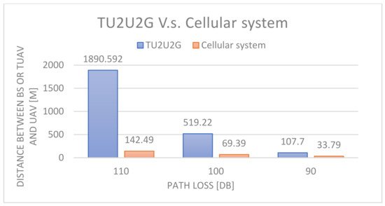
Figure 6. Distance between BS and UAV and distance between TUAV and UAV at different path loss values.
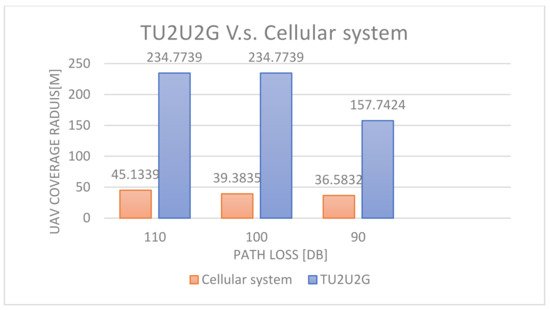
Figure 7. Coverage radius of the UAV for a TU2U2G’s and a cellular system’s different path loss values.
Figure 8 and Figure 9 show the 3D placement for the TU2U2G system and the cellular system respectively. The simulation is done at The A2G path loss = 100 dB. While TU2U is set to different Path loss values 110 dB, 115 dB, 120 dB, and 125 dB. The optimum altitude of the A2G link for PL = 100 dB is 225.9 m and the coverage radius is 208.7 m. In the TU2U2G system, using TUAV allows the UAV to reach the optimum altitude of the A2G link. However, in the cellular system, the maximum coverage of the UAV is 70 m. Figure 10 shows the increase of UAV height and coverage with the increase of the TUAV height. On the other hand, the antenna down tilting and the low height of the Base station limit the UAV height to a max of 70 m which reduces the coverage radius of the UAV.
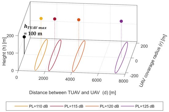
Figure 8. 3D placement of a UAV for TU2U2G system at different path losses.
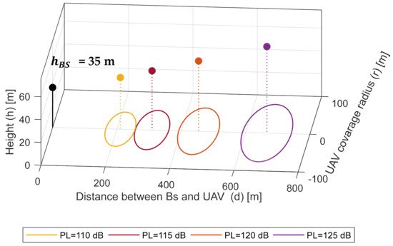
Figure 9. 3D placement of a UAV for cellular system at different path losses.
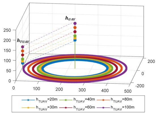
Figure 10. TUAV height versus UAV height and coverage.
This entry is adapted from the peer-reviewed paper 10.3390/electronics11030385
This entry is offline, you can click here to edit this entry!