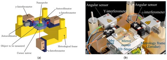
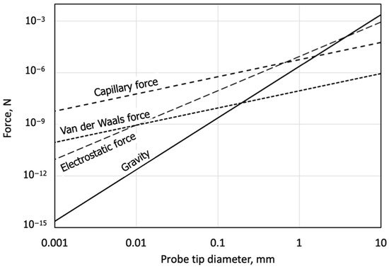
A coordinate measuring machine (CMM) is a measuring instrument that can measure three-dimensional (3D) shapes of an object, including a probing system to detect an object’s surface, a positioning stage system to move either the probing system or the object, length scales to determine the coordinate of detected points by the probing system, as well as software to control the entire measurement. Micro-coordinate measuring machines (micro-CMMs) for measuring microcomponents require a probe system with a probe tip diameter of several tens to several hundreds of micrometers. Scale effects work for such a small probe tip, i.e., the probe tip tends to stick on the measurement surface via surface adhesion forces. These surface adhesion forces significantly deteriorate probing resolution or repeatability.
- micro-CMM
- microprobe system
- coordinate metrology
- surface detection
- dimensional metrology
1. Introduction
|
Conventional CMM |
micro-CMM |
|
|---|---|---|
|
Measuring range |
(1 m)3 |
(10 mm)3 |
|
Resolution |
1 μm |
10 nm |
|
Accuracy |
5 μm |
50 nm |
|
Probe tip size |
5 mm |
50 μm |
|
Measuring force |
10−1 N |
10−3 N |
2. Overview of Microprobe System for Coordinate Metrology
2.1. Issues for Microprobe System
2.2. Contact Probing System with Hinge Structure
|
Sensing Principle |
Probe Tip Diameter |
Shaft Length |
Probing Force |
Probe Tip Material |
|
|---|---|---|---|---|---|
|
Panasonic, UA3P-AFP |
Contact, Hinge-type probe |
30, 80 μm |
300, 500 μm |
0.3 mN |
Ruby, Tungsten carbide |
|
Xpress PE, GANNEN XP |
Contact, Hinge-type Vibration probe |
50–120 μm |
6.8 mm |
0.4 mN |
Ruby |
|
IBS P.E. Trislelion |
Contact, Hinge-type probe |
80–250 μm |
6–8.5 mm |
0.3 mN |
Ruby |
|
3D Werth Fiber Probe |
Contact, Fiber probe |
40–250 μm |
20 mm |
1–100 μN |
Glass |
|
Werth Fiber Probe, WFP/S |
Contact, Fiber probe |
down to 25 μm |
150 mm |
1–100 μN |
Glass |
|
Mitutoyo, UMAP |
Vibration probe |
15–300 μm |
0.2–16 mm |
1–25 μN |
Glass |
|
Zeiss, F25 probe |
Contact, Hinge-type probe |
100–700 μm |
up to 4 mm |
0.5 mN |
Ruby |
2.3. Review the Specification of the Proposed Microprobe System
This entry is adapted from the peer-reviewed paper 10.3390/metrology2010004
References
- ISO10360-1Geometrical Product Specifications (GPS)—Acceptance and Reverification Test for Coordinate Measuring Machines (CMM)—Part 1: Vocabulary, ISO, 2000. Available online: https://www.iso.org/standard/18418.html(accessed on 9 January 2022).
- De Chiffre, L.; Carmignato, S.; Kruth, J.-P.; Schmitt, R.; Weckenmann, A. Industrial applications of computed tomography. CIRP Ann. 2014, 63, 655–677.
- Villarraga-Gómez, H.; Herazo, E.L.; Smith, S.T. X-ray computed tomography: From medical imaging to dimensional metrology. Precis. Eng. 2019, 60, 544–569.
- Hocken, R.J.; Pereira, P.H. Coordinate Measuring Machines and Systems; CRC Press: London, UK, 1995.
- Dornfeld, D.; Min, S.; Takeuchi, Y. Recent advances in mechanical micromachining. CIRP Ann. 2006, 55, 745–768.
- Vaezi, M.; Seitz, H.; Yang, S. A review on 3D micro-additive manufacturing technologies. Int. J. Adv. Manuf. Technol. 2013, 67, 1721–1754.
- Giboz, J.; Copponnex, T.; Mele, P. Microinjection molding of thermoplastic polymers: A review. J. Micromech. Microeng. 2007, 17, R96–R109.
- Kunieda, M.; Lauwers, B.; Rajurkar, K.P.; Schumacher, B.M. Advancing EDM through Fundamental Insight into the Process. CIRP Ann. 2005, 54, 64–87.
- Hansen, H.N.; Carneiro, K.; Haitjema, H.; De Chiffre, L. Dimensional Micro and Nano Metrology. CIRP Ann. 2006, 55, 721–743.
- Takamasu, K.; Ozawa, S.; Asano, T.; Suzuki, A.; Furutani, R.; Ozono, S. Basic concepts of nano-CMM-Coordinate Measuring Machine with Nanometer Resolution. In Proceedings of the 1996 Japan-China Bilateral Symposium on Advanced Manufacturing Engineering, Tokyo, Japan; 1996; pp. 155–158. Available online: http://www.nanolab.t.u-tokyo.ac.jp/pdffiles/nichu-nano09.pdf (accessed on 9 January 2022).
- Cao, S.; Brand, U.; Kleine-Besten, T.; Hoffmann, W.; Schwenke, H.; Bütefisch, S.; Büttgenbach, S. Recent developments in dimensional metrology for microsystem components. Microsyst. Technol. 2002, 8, 3–6.
- Brand, U.; Kirchhoff, J. A micro-CMM with metrology frame for low uncertainty measurements. Meas. Sci. Technol. 2005, 16, 2489–2497.
- Peggs, G.; Lewis, A.; Oldfield, S. Design for a Compact High-Accuracy CMM. CIRP Ann. 1999, 48, 417–420.
- Liang, S.Y. Mechanical machining and metrology at micro/nano scale. In Proceedings of the SPIE 6280, Third International Symposium on Precision Mechanical Measurements, Xinjiang, China, 2–6 August 2006.
- Okabe, K. Development of an ultra-precision CMM for 3D measurement of large parts. In Proceeding of the JSPE Spring Meeting, Tokyo, Japan, 16–18 August 2006; pp. 1163–1164. (In Japanese).
- Tsutsumi, H.; Yoshizumi, K.; Takeuchi, H. Ultrahighly accurate 3D profilometer. In Proceedings of the SPIE 5638, Optical Design and Testing II; SPIE: Bellingham, DC, USA, 2005.
- Fan, K.C.; Fei, Y.T.; Yu, X.F.; Chen, Y.J.; Wang, W.L.; Chen, F.; Liu, Y.S. Development of a low-cost micro-CMM for 3D micro/nano measurements. Meas. Sci. Technol. 2006, 17, 524–532.
- Donker, R.L.; Widdershoven, I.; Spaan, H.A.M. Isara 400: Enabling Ultra-precision Coordinate Metrology for Large Parts. In Proceedings of the 10th Euspen International Conference, Delft, The Netherlands, 31 May–4 June 2010; Volume 1, pp. 204–208.
- Claverley, J.; Leach, R. A review of the existing performance verification infrastructure for micro-CMMs. Precis. Eng. 2015, 39, 1–15.
- Vermeulen, M.; Rosielle, P.; Schellekens, P. Design of a High-Precision 3D-Coordinate Measuring Machine. CIRP Ann. 1998, 47, 447–450.
- Jäger, G. Three-dimensional nanopositioning and nanomeasuring machine with a resolution of 0.1 nm. Optoelectron. Instrum. Data Process. 2010, 46, 318–323.
- Leach, R.; Haycocks, J.; Jackson, K.; Lewis, A.; Oldfield, S.; Yacoot, A. Advances in traceable nanometrology at the National Physical Laboratory. Nanotechnology 2000, 12, R1–R6.
- Widdershoven, I.; Donker, R.L.; Spaan, H.A.M. Realization and calibration of the “Isara 400” ultra-precision CMM. J. Phys. Conf. Ser. 2011, 311, 012002.
- Moers, A.J.M.; van Riel, M.C.J.M. Design and verification of the Trinano ultra precision CMM. In Proceedings of the 56th International Scientific Colloquium, Ilmenau, Germany, 12–16 September 2011; pp. 12–16.
- Manske, E.; Jäger, G.; Hausotte, T.; Füßl, R. Recent developments and challenges of nanopositioning and nanomeasuring technology. Meas. Sci. Technol. 2012, 23, 074001.
- Jäger, G.; Manske, E.; Hausotte, T.; Müller, A.; Balzer, F. Nanopositioning and nanomeasuring machine NPMM-200—A new powerful tool for large-range micro- and nanotechnology. Surf. Topogr. Metrol. Prop. 2016, 4, 034004.
- Schwenke, H.; Hartig, F.; Wendt, K.; Waldele, F. Future challenges in Co-ordinate metrology: Addressing metrological problems for very small and very large parts. In Proceedings of the IDW Conference, Knoxville, TN, USA, 7–10 May 2001; pp. 1–12.
- Weckenmann, A.; Estler, T.; Peggs, G.; McMurtry, D. Probing Systems in Dimensional Metrology. CIRP Ann. 2004, 53, 657–684.
- Weckenmann, A.; Peggs, G.; Hoffmann, J. Probing systems for dimensional micro- and nano-metrology. Meas. Sci. Technol. 2006, 17, 504–509.
- Fan, K.-C.; Li, R.-J.; Xu, P. Design and Verification of Micro/Nano-Probes for Coordinate Measuring Machines. Nanomanuf. Metrol. 2018, 2, 1–15.
- Claverley, J.D.; Leach, R. A vibrating micro-scale CMM probe for measuring high aspect ratio structures. Microsyst. Technol. 2009, 16, 1507–1512.
- Michihata, M.; Yoshikane, T.; Hayashi, T.; Takaya, Y. New technique for single-beam gradient-force optical trapping in air. Int. J. Optomechatronics 2013, 7, 46–59.
- Murakami, H.; Katsuki, A.; Sajima, T.; Fukuda, M. Reduction of Liquid Bridge Force for 3D Microstructure Measurements. Appl. Sci. 2016, 6, 153.
- Bos, E. Aspects of tactile probing on the micro scale. Precis. Eng. 2011, 35, 228–240.
- Dai, G.; Neugebauer, M.; Stein, M.; Bütefisch, S.; Neuschaefer-Rube, U. Overview of 3D Micro- and Nanocoordinate Metrology at PTB. Appl. Sci. 2016, 6, 257.
- Kinnell, P.; Habeb, R.R. An evaluation of cleaning methods for micro-CMM probes. Meas. Sci. Technol. 2013, 24, 085603.
- Murakami, H.; Katsuki, A.; Onikura, H.; Sajima, T.; Kawagoishi, N.; Kondo, E. Development of a System for Measuring Micro Hole Accuracy Using an Optical Fiber Probe. J. Adv. Mech. Des. Syst. Manuf. 2010, 4, 995–1004.
- Meli, F.; Küng, A. AFM investigation on surface damage caused by mechanical probing with small ruby spheres. Meas. Sci. Technol. 2007, 18, 496–502.
- Nicolet, A.; Küng, A.; Meli, F. Study of sapphire probe tip wear when scanning on different materials. Meas. Sci. Technol. 2012, 23, 094016.
- Küng, A.; Nicolet, A.; Meli, F. Study of wear of diamond-coated probe tips when scanning on different materials. Meas. Sci. Technol. 2015, 26, 084005.
- Van Vliet, W.; Schellekens, P. Accuracy Limitations of Fast Mechanical Probing. CIRP Ann. 1996, 45, 483–487.
- Claverley, J.D.; Burisch, A.; Leach, R.; Raatz, A. Semi-automated Assembly of a MEMS-Based Micro-scale CMM Probe and Future Optimization of the Process Chain with a View to Desktop Factory Automation. In Precision Assembly Technologies and Systems. IPAS 2012. IFIP Advances in Information and Communication Technology; Ratchev, S., Ed.; Springer: Berlin/Heidelberg, Germany, 2012; Volume 371.
- Dai, G.; Wolff, H.; Weimann, T.; Xu, M.; Pohlenz, F.; Danzebrink, H.-U. Nanoscale surface measurements at sidewalls of nano- and micro-structures. Meas. Sci. Technol. 2007, 18, 334–341.
- Li, R.; Chen, C.; Li, D.; Fan, K.-C.; Cheng, Z.; Huang, Q.; Dang, X. Ball Tips of Micro/Nano Probing Systems: A Review. Chin. J. Mech. Eng. 2017, 30, 222–230.
- Murakami, H.; Katsuki, A.; Sajima, T.; Uchiyama, K. Fabrication of Ultra-Small-Diameter Optical-Fiber Probe Using Acid-Etch Technique and CO2 Laser for 3D-Micro Metrology. Int. J. Autom. Technol. 2017, 11, 699–706.
- Sheu, D.-Y. Study on an evaluation method of micro CMM spherical stylus tips by µ-EDM on-machine measurement. J. Micromech. Microeng. 2010, 20, 075003.
- Muralikrishnan, B.; Stone, J.; Stoup, J. Fiber deflection probe for small hole metrology. Precis. Eng. 2006, 30, 154–164.
- Ito, S. Micro-dimensional Measurement by a Micro-probing System. In Metrology. Precision Manufacturing; Gao, W., Ed.; Springer: Singapore, 2019.
- Yu, H.; Huang, Q.; Zhao, J. Fabrication of an Optical Fiber Micro-Sphere with a Diameter of Several Tens of Micrometers. Materials 2014, 7, 4878–4895.
- Sheu, D.-Y. Micro-spherical probes machining by EDM. J. Micromech. Microeng. 2005, 15, 185–189.
- Li, R.; Chen, C.; Fan, K.; Wang, Z.; Liu, F.; Huang, Q. Fabrication and Study of Micro Monolithic Tungsten Ball Tips for Micro/Nano-CMM Probes. Micromachines 2018, 9, 133.
- Chen, L.-C. Automatic 3D surface reconstruction and sphericity measurement of micro spherical balls of miniaturized coordinate measuring probes. Meas. Sci. Technol. 2007, 18, 1748.
- Fan, K.-C.; Wang, N.; Wang, Z.-W.; Zhang, H. Development of a roundness measuring system for microspheres. Meas. Sci. Technol. 2014, 25, 064009.
- Medicus, K.M.; Jansen, M. Diameter measurement of small spheres on a white light interferometer including uncertainty analysis. In Proceedings of the 10th Euspen International Conference, Delft, The Netherlands, 31 May–4 June 2010; p. 75.
- Michihata, M.; Hayashi, T.; Adachi, A.; Takaya, Y. Measurement of probe-stylus sphere diameter for micro-CMM based on spectral fingerprint of whispering gallery modes. CIRP Ann. 2014, 63, 469–472.
- Kobayashi, Y.; Michihata, M.; Zheng, Z.; Chu, B.; Takamasu, K.; Takahashi, S. Radial mode number identification on whis-pering gallery mode resonances for diameter measurement of microsphere. Meas. Sci. Technol. 2019, 30, 065201.
- Spaan, H.A.M.; Widdershoven, I.; Morel, M.A.A. Novel calibration techniques and applications for touch probes with na-nometre accuracy. In Proceedings of the Euspen International Conference, Vienna, Austria, 28 May–1 June 2006; p. 386.
- Fang, C.-Z.; Huang, Q.-X.; Ding, X.-M.; Cheng, R.-J.; Zhang, L.; Wang, C.-Q.; Mei, J.; Li, H.-L. Measurement and uncertainty evaluation of the microsphere used for micro-CMM probe. Meas. Sci. Technol. 2020, 31, 025004.
- Kung, A.; Meli, F.; Thalmann, R. Ultraprecision micro-CMM using a low force 3D touch probe. Meas. Sci. Technol. 2007, 18, 319–327.
- Thalmann, R.; Meli, F.; Küng, A. State of the Art of Tactile Micro Coordinate Metrology. Appl. Sci. 2016, 6, 150.
- Ito, S.; Tsutsumi, D.; Kamiya, K.; Matsumoto, K.; Kawasegi, N. Measurement of form error of a probe tip ball for coordinate measuring machine (CMM) using a rotating reference sphere. Precis. Eng. 2020, 61, 41–47.
- Schaude, J.; Baumgärtner, B.; Hausotte, T. Bidirectional confocal measurement of a microsphere. Appl. Opt. 2021, 60, 8890–8895.
- Haitjema, H.; Pril, W.; Schellekens, P. Development of a Silicon-based Nanoprobe System for 3-D Measurements. CIRP Ann. 2001, 50, 365–368.
- Pornnoppadol, P.; Cao, S.; Schmidt, M.; Wilke, R.; Bütefisch, S.; Nesterov, V.; Brand, U. Three-dimensional microprobe with reduced probing forces. In Proceedings of the Euspen International Conference, Eindhoven, The Netherlands, 26–30 May 2002; pp. 737–740.
- Ogura, I.; Okazaki, Y. Development of microprobe for micro-CMM. In Proceedings of the 17th annual meeting of ASPE, St. Louis, MO, USA, 20–25 October 2002; pp. 349–352.
- Takamasu, K.; Chih-Che, K.; Suzuki, A.; Hiraki, M.; Furutani, R.; Ozono, S. Development of Pneumatic Ball Probe for Measuring Small Hole. In Proceedings of the ICPE’97, Taipei, Taiwan, 20–22 November 1997; pp. 767–771.
- Ruther, P.; Bartholomeyczik, J.; Trautmann, A.; Wandt, M.; Paul, O.; Dominicus, W.; Roth, R.; Seitz, K.; Strauss, W. Novel 3D Piezoresistive Silicon Force Sensor for Dimensional Metrology of Micro Components. In Proceedings of the IEEE Sensors 2005, Irvine, CA, USA, 30 October–3 November 2005; p. 4.
- Takaya, Y.; Shimizu, H.; Takahashi, S.; Miyoshi, T. Fundamental study on the new probe technique for the nano-CMM based on the laser trapping and Mirau interferometer. Measurement 1999, 25, 9–18.
- Hidaka, K.; Schellekens, P. Study of a Small-sized Ultrasonic Probe. CIRP Ann. 2006, 55, 567–570.
- Wang, W.-L.; Fan, K.-C.; Chen, Y.-J. Development of a touch trigger probe for micro/nano CMM. In Proceedings of the Fourth International Symposium on Precision Mechanical Measurements; SPIE: Bellingham, DC, USA, 2008; Volume 7130, p. 71300.
- Dai, G.; Bütefisch, S.; Pohlenz, F.; Danzebrink, H.-U. A high precision micro/nano CMM using piezoresistive tactile probes. Meas. Sci. Technol. 2009, 20, 084001.
- Fan, K.-C.; Cheng, F.; Pan, W.-T.; Li, R. Analysis of the Contact Probe Mechanism for Micro-Coordinate Measuring Machines, Optoelectronics. Instrum. Data Process. 2010, 46, 340–346.
- He, M.; Liu, R.; Li, Y.; Wang, H.; Lu, X.; Ding, G.; Wu, J.; Zhang, T.; Zhao, X. Tactile probing system based on micro-fabricated capacitive sensor. Sens. Actuators A Phys. 2013, 194, 128–134.
- Cui, J.; Bian, X.; He, Z.; Li, L.; Sun, T. A 3D nano-resolution scanning probe for measurement of small structures with high aspect ratio. Sensors Actuators A Phys. 2015, 235, 187–193.
- Li, J.; Cui, J.; Tan, J. Design of Three-dimensional Isotropic Microprobe Based on Three-Flexible-Hinge Suspension for Measurement of Microstructures. IEEE/ASME Trans. Mechatron. 2020, 25, 2123–2133.
- Alblalaihid, K.; Kinnell, P.; Lawes, S. Fabrication and characterisation of a novel smart suspension for micro-CMM probes. Sens. Actuators A Phys. 2015, 232, 368–375.
- Chu, C.-L.; Chen, H.-C. Development of a surface scanning touch probe for micro-CMM. In Proceedings of the 2017 International Conference on Applied System Innovation (ICASI), Sapporo, Japan, 13–17 May 2017; pp. 1942–1945.
- Liu, F.; Wang, J.; Chen, L.; Li, R.; Xia, H.; Yu, L. Development and characterization of a high-sensitivity fiber Bragg grating-based vibrating nano-probe for 3D measurement. Sens. Rev. 2019, 39, 199–207.
- Lei, L.; Deng, L.; Fan, G.; Cai, X.; Li, Y.; Li, T. A 3D micro tactile sensor for dimensional metrology of micro structure with nanometer precision. Measurement 2014, 48, 155–161.
- Kao, S.-M.; Sheu, D.-Y. Developing a novel tri-switch tactile probing structure and its measurement characteristics on micro-CMM. Measurement 2013, 46, 3019–3025.
- Li, R.-J.; Xiang, M.; He, Y.-X.; Fan, K.-C.; Cheng, Z.-Y.; Huang, Q.-X.; Zhou, B. Development of a High-Precision Touch-Trigger Probe Using a Single Sensor. Appl. Sci. 2016, 6, 86.
- Development of Micro Contact Detection Probe for Microhole Quality Control. Int. J. Autom. Technol. 2011, 5, 102–108.
- Ogura, I.; Ashida, K. Development of on-machine measurement system for micro-factory–Contact and non-contact combined probe–. In Proceedings of the 9th International Workshop on Microfactories(IWMF2014), Honolulu, HI, USA, 5–8 October 2014; pp. 1–6.
- Metz, D.; Jantzen, S.; Wessel, D.; Mies, G.; Lüdenbach, J.; Stein, M.; Kniel, K.; Dietzel, A. Integration of an isotropic microprobe and a microenvironment into a conventional CMM. Meas. Sci. Technol. 2019, 30, 115007.
- Metz, D.; Dietzel, A. 3-D Isotropic Tactile Microprobe Based on a Silicon Parallelogram Kinematic: From Concept to Fabrication. J. Microelectromech. Syst. 2018, 28, 63–76.
- Nesterov, V.; Brand, U. Modelling and investigation of the silicon twin design 3D micro probe. J. Micromech. Microeng. 2004, 15, 514–520.
- Van Riel, M.C.J.M.; Bos, E.J.C. 3D Vibrating Probe For Measuring Microfeatures With Nanometer Un-Certainty. In Proceedings of the 56th International Scientific Colloquium, Ilmenau, Germany, 12–16 September 2011.
- Wiegmann, A.; Schulz, M.; Yoshizumi, K.; Kubo, K.; Ramm, D. Comparison of a Scanning Interferometric Profile Measurement Method and an Ultra-Precise Coordinate Measuring Machine. In Proceedings of the 10th IMEKO TC14 Symposium on Laser Metrology for Preci-sion Measurement and Inspection in Industry, Braunschweig, Germany, 12–14 September 2011.
- Spaan, H.A.M.; Widdershoven, I. Isara 400 ultra-precision CMM. In Proceedings of the SPIE Optical Systems Design; SPIE: Bellingham, DC, USA, 2011; Volume 8169, p. 81690.
- Habeb, R.R.; Kinnell, P. Evaluation Tip Cleaning for a Micro CMM Touch Trigger Stylus Sensor. Procedia Eng. 2012, 47, 306–309.
- Bergmans, R.H.; Nieuwenkamp, H.J.; van Veghel, M.G.A. Probing behavior of a micro CMM. In Proceedings of the 11th Euspen International Conference, Como, Italy, 23–26 May 2011; Volume 1, pp. 104–107.
- Nouira, H.; Bergmans, R.; Küng, A.; Pirée, H.; Henselmans, R.; Spaan, H. Ultra-high precision CMMs and their associated tactile or/and optical scanning probes. Int. J. Metrol. Qual. Eng. 2014, 5, 204.
- Lewis, A.; Oldfield, S.; Peggs, G.N. The NPL small CMM-3-D measurement of small features. In Laser Metrology and Machine Performance; WIT Press: Southampton, UK, 2001; pp. 197–207.
- Brand, U.; Kleine-Besten, T.; Schwenke, H. Development of a special CMM for dimensional metrology on microsystem components. ASPE 2000, 542, 15.
- Bos, E.J.C.; Delbressine, F.L.M.; Haitjema, H. High-Accuracy CMM Metrology for Micro Systems. In Proceedings of the 8th International Symposium on Measurement and Quality Control in Production, Erlangen, Germany, 12–15 October 2004; 2004; pp. 511–522.
- Meli, F.; Bieri, M.; Thalmann, R.; Fracheboud, M.; Breguet, J.; Clavel, R.; Bottinelli, S. Novel 3D analogue probe with a small sphere and low measurement force. In Proceedings of the ASPE Summer Topical Meeting, Charlotte, NC, USA, 25–26 June 2003.
- Claverley, J.D.; Leach, R. Development of a three-dimensional vibrating tactile probe for miniature CMMs. Precis. Eng. 2013, 37, 491–499.
- Stoyanov, S.; Bailey, C.; Leach, R.; Hughes, B.; Wilson, A.; O’Neill, W.; Dorey, R.A.; Shaw, C.; Underhill, D.; Almond, H.J. Modelling and prototyping the conceptual design of 3D CMM micro-probe. In Proceedings of the 2008 2nd Electronics Systemintegration Technology Conference, Greenwich, UK, 1–4 September 2008; pp. 193–198.
- Alblalaihid, K.; Kinnell, P.; Lawes, S.; Desgaches, D.; Leach, R. Performance Assessment of a New Variable Stiffness Probing System for Micro-CMMs. Sensors 2016, 16, 492.
- Goj, B.; Dressler, L.; Hoffmann, M. Design and characterization of a resonant triaxial microprobe. J. Micromech. Microeng. 2015, 25, 125011.
- Cui, J.; Li, J.; Feng, K.; Tan, J.; Zhang, J. A 3D fiber probe based on orthogonal micro focal-length collimation and fiber Bragg grating. Meas. Sci. Technol. 2016, 27, 074005.
- Ji, H.; Hsu, H.-Y.; Kong, L.X.; Wedding, A.B. Development of a contact probe incorporating a Bragg grating strain sensor for nano coordinate measuring machines. Meas. Sci. Technol. 2009, 20, 095304.
- Eom, S.I.; Takaya, Y.; Hayashi, T. Novel contact probing method using single fiber optical trapping probe. Precis. Eng. 2009, 33, 235–242.
- Cui, J.; Li, L.; Li, J.; Tan, J.B. Fiber probe for micro-hole measurement based on detection of returning light energy. Sens. Actuators A Phys. 2013, 190, 13–18.
- Murakami, H.; Katsuki, A.; Sajima, T. Development of Touch Probing System Using a Fiber Stylus. Fibers 2016, 4, 24.
- Muralikrishnan BStone JStoup, J.; Sahay, C. Micro-Feature Dimensional and Form Measurements with the NIST Fiber Probe on A CMM. Cal Lab Int. J. Metrol. 2010, 17, 25. Available online: https://tsapps.nist.gov/publication/get_pdf.cfm?pub_id=903944 (accessed on 24 September 2021).
- Neuschaefer-Rube, U.; Bremer, H.; Hopp, B.; Christoph, R. Recent developments of the 3d fiber probe. In Proceedings of the 11th Laser Metrology for Precision Measurement and Inspection in Industry 2014, Tsukuba, Japan, 2–5 September 2014.
- Cui, J.; Li, J.; Feng, K.; Tan, J. Three-dimensional fiber probe based on orthogonal micro focal-length collimation for the measurement of micro parts. Opt. Express 2015, 23, 26386–26398.
- Murakami, H.; Katsuki, A.; Sajima, T.; Uchiyama, K.; Yoshida, I.; Hamano, Y.; Honda, H. Development of measurement system for microstructures using an optical fiber probe: Improvement of measurable region and depth. Meas. Sci. Technol. 2020, 31, 075902.
- Petz, M.; Tutsch, R.; Christoph, R.; Andraes, M.; Hopp, B. Tactile—optical probes for three-dimensional microparts. Measurement 2012, 45, 2288–2298.
- Murakami, H.; Katsuki, A.; Sajima, T.; Suematsu, T. Study of a vibrating fiber probing system for 3-D micro-structures: Performance improvement. Meas. Sci. Technol. 2014, 25, 094010.
- Oiwa, T.; Nishitani, H. Three-dimensional touch probe using three fibre optic displacement sensors. Meas. Sci. Technol. 2003, 15, 84–90.
- Zou, L.; Ni, H.; Zhang, P.; Ding, X. Assembled Cantilever Fiber Touch Trigger Probe for Three-Dimensional Measurement of Microstructures. Sensors 2017, 17, 2652.
- Kubo, K. Laser Based Asphere And Freeform Measurement Technology By Ua3p. In Proceedings of the 11th Laser Metrology for Precision Measurement and Inspection in Industry 2014, Tsukuba, Japan, 2–5 September 2014.
- Ito, S.; Kodama, I.; Gao, W. Development of a probing system for a micro-coordinate measuring machine by utilizing shear-force detection. Meas. Sci. Technol. 2014, 25, 064011.
- Huang, Q.; Chen, C.; Wu, K.; Zhang, L.; Li, R.-J.; Fan, K.-C. A Three-Dimensional Resonant Triggering Probe for Micro-CMM. Appl. Sci. 2017, 7, 403.