Your browser does not fully support modern features. Please upgrade for a smoother experience.
Please note this is an old version of this entry, which may differ significantly from the current revision.
Subjects:
Engineering, Electrical & Electronic
The storage of enormous energies is a significant challenge for electrical generation. Researchers have studied energy storage methods and increased efficiency for many years. In recent years, researchers have been exploring new materials and techniques to store more significant amounts of energy more efficiently. In particular, renewable energy sources and electric vehicle technologies are triggering these scientific studies. Scientists and manufacturers recently proposed the supercapacitor (SC) as an alternating or hybrid storage device.
- supercapacitor
- materials
- application of supercapacitors
- modelling of supercapacitors
- performance of supercapacitors
1. Introduction
Repeated natural events and fossil fuels are primary energy sources. Storing and regulating energy is an immediate problem of these sources [1]. The energy must keep its immensely sized potential to be supplied uninterrupted [2]. Energy sources are converted into different forms and partially stored in the grid system for energy peak shaving [3]. Moreover, these sources can be stored for interruptible and temporal gaps between energy generation and end-user consumption [4]. The storage of water energy in dams [5], the storage of energy as hydrogen [6], and electrochemical storage devices [7] are the primary storage systems used today. The storage the energy as electrical energy directly is possible with electrochemical storage devices [3,8]. However, the lifespan of these conventional storage devices is less than half that of the supercapacitor (SC), most of them contain some contaminants that are harmful to nature, and they have some technical drawbacks [8,9]. Although iron-based flow batteries have a long life and are environmentally friendly, they have a lower energy density due to many aqueous solutions [8]. Thus, scientists have been researching storage devices with a large capacity and long life for many years [10,11].
Scientists have proposed SCs as an alternate solution for individual and hybrid applications with other storage devices [12]. In addition, as the power source for electric and hybrid vehicles, SCs are increasingly used as interim energy storage for regenerative braking [13]. The SCs have several advantages, including high power density, quick charge–discharge time, low input resistance, extended lifetime, and they are environmentally friendly [3,14]. Several hybridisation topologies have been proposed and applied during the last decade to increase the power density and cycle life of energy storage systems [15,16,17,18]. The latest technologies stimulate placing SCs into direct contest with rechargeable batteries [19]. Thus, the electrochemical activities of some materials and their composites have been investigated for possible methods to apply these materials in Li-ion batteries in the future [9,19]. The SC can store electrical energy as a solid-state device to overcome many of the shortcomings of batteries [13].
SCs were invented in the middle of the 19th century, and they have a new history. Firstly, General Electric (GE) corporation engineers designed capacitors in the early 1950s and 1957. The first SC was developed without a known double layer by Becker [20]. The SOHIO company expanded another version of the SC in 1966, and it was patented as an electrolytic capacitor [21,22]. The first SCs for military application were developed by the Pinnacle Research Institute (PRI) in 1982, called PRI ultra-capacitors. At the end of 1980, the charge and discharge currents increased, dependent on increasing capacitance values, and the equivalent series resistance (ESR) values decreased. In 1992, Maxwell Laboratories took over this development and named them “Boost Caps” to emphasise their power applications [23]. Evans developed a high voltage tantalum electrolytic capacitor in 1994, which combined the properties of electrolytic and electrochemical capacitors; however, it was limited to specific military applications [24,25]. Lithium-ion capacitors recently developed by the FDK group corporation, called hybrid capacitors, combine an electrostatic carbon electrode with an electrochemical electrode to increase the capacitance value [26,27]. Today, SC research aims to improve SC characteristics, increase performance, and decrease production costs [28,29].
The structure of the SC differs from a ceramic or electrolytic capacitor. It consists of two solid electrodes polarized by an applied voltage and separated by a membrane separator and a liquid electrolyte [30,31]. The electric double layer (EDL) capacitor, also called an ultra-capacitor, consists of ions in the electrolyte that form EDLs of reverse polarity to the electrodes [3,30]. Double-layer capacitance is one of the two storage principles, where electrostatic storage is achieved by separating charge in a Helmholtz double-layer and increasing the capacitance of SCs [32,33]. The other type of electrochemical storage is pseudocapacitance, which is reached by faradaic redox reactions. These two principles can be separated only by measurement techniques [23].
The functionality and characteristics of the SC originate from the mutual effect of its electrode and electrolyte materials. The electrode material for EDL capacitors is usually activated carbon, carbon fibre cloth, and aerogel, graphite, graphene, and carbon nanotubes in different appearances of carbon [33,34,35]. A pseudocapacitive material uses electron-conducting polymers with low ESR, high capacitance, and cycles, because not every material can be used as an electrode for pseudocapacitors [36,37]. The hybrid-type SCs combine two electrodes with a high pseudocapacitance and double-layer capacitance manufactured from carbon-based materials [38]. The development of hybrid-type supercapacitor electrodes influenced rechargeable battery electrodes [39] positively. Regarding the electrolyte materials, electrolytes consist of a solvent and dissolved chemicals. For better electrical conductivity, more ions are required in the electrolyte and aqueous, organic, and ionic electrolytes used [40]. The two electrodes are separated physically by separators to hinder short circuits, and they must be skinny and porous to minimise the equivalent series resistance (ESR). Generally, inexpensive components are used for separators; more complex designs use nonwoven porous polymeric films, woven glass fibres, or porous woven ceramic fibres [41]. Finally, the electrodes connect to the current collectors of the capacitor’s terminals to distribute high peak currents.
The advantages of SCs make them superior to other storage devices, while they also have some drawbacks. Comparing the benefits and disadvantages, it seems reasonable to use them together [3,14]. The advantages and drawbacks of various electrochemical storage devices are related to their energy and power density values and charging period [42]. The performance analyses of SCs are compared with the other storage devices in many studies, which have shown that using the SCs in combination with the other storage devices is reasonable in many ways [43,44,45]. These superiorities have been investigated for hybrid photovoltaic (PV)–battery SC energy storage systems [14,42,45,46,47,48]. In addition, PV–battery SCs or fuel cells including hybrid energy storage systems (HESSs) have been proposed in some studies [49,50]. Some studies have simulated and compared HESSs for battery life and daily costs [12,43]. The performance and cost analyses gave better results for SCs including HESSs [51,52,53].
The commercial companies and product situations, the market structure, and the new developments in the market are the other essential points to be investigated in more detail to elucidate the future trend of SCs. SC worldwide sales have been about 400 million USD since 2016 [54]. The battery market has grown from 47.5 billion to 95 billion USD [55]. The SC market is still small; however, it is foreseen that sales will grow with an annual increase of about 24%, from 240 million to 2 billion USD by 2026 [56]. SC costs in 2006 were 0.01 USD/F or 2.85 USD/kJ, moving in 2008 to below 0.01 USD/F, and decreasing every year [57]. Current electrical double layer capacitors (EDLCs) contain organic electrolytes that operate at 2.7 V and reach energy densities around 5–8 Wh/kg or 7–10 Wh/L [58]. Today, a commercial corporation offers a 48 V ultra-capacitor module with 1,000,000 duty cycles or a ten-year DC life and 48 V DC working voltage [59]. The modules are engineered explicitly for hybrid bus and construction equipment to provide cost-effective solutions. Still, they are also widely utilized in electronics applications for cell balancing [60,61].
The SC has some advantages in applications with high power density, and many charge and discharge cycles are required for longer life. General applications of SCs are for shorter periods from low to high power, and they are not used for alternating currents (AC). Some applications of SCs are in consumer electronics [62,63], tools, power supply [64], voltage stabilisation [65], microgrid [66], renewable energy storage [3], energy harvesting [67,68], street lights [69], medical applications [70], military and automotive applications [71,72,73], and energy recovery [74,75,76,77]. These will be explored in more detail with examples in the next sections. Standardised test protocols are required for applications ranging from low to high peak currents [78]. A current report calculated that if only a few percent of 48V mild-hybrid systems use SC peak shaving in ten years, a yearly additional SC market of over 0.5 billion USD will emerge in 2030 [79].
SC modelling and charge–discharge simulations to define capacitance and internal resistance are another research topic. Some primary studies were found in the literature where the different characteristics and the dynamic structure of SCs were investigated and simulated [80,81,82,83,84,85,86]. Zubieta and Faranda designed an equivalent electrical circuit model for simulations suitable for power applications [87,88]. In other studies, a two-branched electrical circuit model was used for the SC module simulation [89,90,91]. A method used to determine some SC equivalent circuit parameters experimentally has also been discussed in the literature [90,92]. A simplified SC module model is required in real-time simulations [93]. SCs based on a simplified equivalent circuit model are made for SC stack performance investigation [93,94]. This stack, called a module, is specifically engineered to provide solutions for industrial electronics applications [59,93]. A module was designed by making use of 20 pieces of 310 F, 2.7 V SCs. Charge–discharge tests for different load conditions were conducted for each capacitor and module and were confirmed with simulation results [95]. Another topic related to the development of SCs is the assembly and manufacturing of SCs. The three widespread SC designs used commercially are coin cells, cylindrical cells, and pouch cells. [96,97,98,99].
2. Fundamental of Supercapacitors
2.1. Structure and Specifications
The structure, working principle, specifications, classifications, and materials of SCs are summarised in this section. The fundamental concept of SCs is based on electrostatic capacitors, and is given in Equation (1). In this equation, the permittivity of air (ε0), relative permittivity of the dielectric material (εr), the surface area (A), and the distance between two electrodes (d) are seen in Figure 1a [94]. The capacitance is adjusted by changing the dielectric material’s surface area and thickness according to the relationship in Equation (1).
(1)
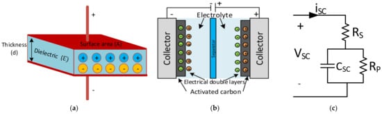
Figure 1. (a) Structure of electrostatic capacitor [94], (b) structure of SC [101], (c) equivalent circuit model of SC [102].
The basic structure of an SC consists of aluminium current collectors and electrodes instead of dielectric materials. The operation principle of the SC is based on the storage of energy by the distribution of the ions near the surface of the two electrodes. The two interfaces create a space charge zone called the electrical double layer (EDL), as shown in Figure 1b. Therefore, an SC is electrostatic, and there is no electrochemical reaction [100,101].
The electrical equivalent circuit model of an SC is given in Figure 1c. Here, the series resistance (Rs) to the capacitor symbolises the equivalent series resistance (ESR). In contrast, the parallel resistance (Rp) across the capacitor represents the resistance estimated according to the leakage currents, and the capacitance (CSC) represents the total capacitance of the SCs. The parameters mentioned in the catalogue data can be used to calculate maximum peak current in a second and specific maximum power value, as shown in Equations (2) and (3) [102].
(2)
(3)
The main properties of SCs are low energy and high power density, fast charge and discharge, the termination of energy flow when fully charged, minimal internal resistance (ESR), long shelf life, and extended lifetime. The advantages of SCs make them superior to the other conventional storage devices in many ways. Comparing their distinctions and drawbacks, using SCs with other storage devices appears to be suitable [42]. SCs are low voltage components and require safe operation, where the voltage remains within specified limits. Standard SCs with aqueous electrolytes are rated within a voltage range of 2.1 to 2.3 V, and SCs with organic solvents are rated from 2.5 to 2.7 V [40]. For higher voltage requirements, the SC cells are connected in series. The rated capacitance value is between 1 F to 1000 F; for higher applications, capacitances are required to connect SC cells in parallel [3,95]. Figure 2 shows that the SCs can bridge batteries and capacitors [94,103,104]. The energy density of SCs is greater than in the conventional capacitors; however, the power density of capacitors is greater than in the SCs.
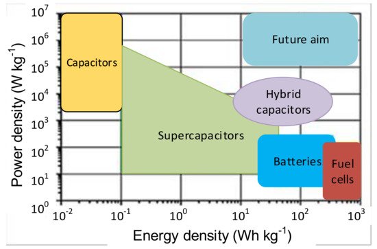
Figure 2. Comparison of the energy and power density of storage devices [103].
2.2. Classifications
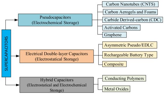
SCs can be classified depending on their manufacturing and construction details. SCs can be made in flat, cylindrical, or rectangular case styles [105,106]. The operation principle of SCs is based on energy storage and, depending on the energy storage method, SCs are divided into three main groups. SCs can be divided into EDLCs and pseudocapacitors (PCs) depending on the energy storage method. Charge storage occurs between the electrolyte and electrodes in EDLC, as shown in Figure 1b. PCs involve reversible and fast Faradaic redox reactions for charge in order to increase the capacitance of the SC, as shown in Figure 3a. A hybrid supercapacitor (HSC) stores the charges by matching the capacitive carbon electrode with a pseudocapacitive or lithium-insertion electrode, as shown in Figure 3b [107,108,109].
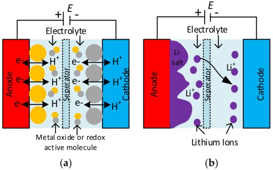
Figure 3. (a) Configuration of a pseudocapacitor (PC) and (b) a hybrid supercapacitor (HSC) [109].
EDLCs consist of two carbon-based electrode materials, enough electrolytes, and a separator. EDLCs can either store charges electrostatically or via a non-Faradaic method, without the transfer of charge loads with the electrochemical double-layer storage principle [108,110,111]. The three main types of EDLCs have a specific condition of the carbon substance. Carbon nanotubes (CNTs), graphene, carbon aerogels and foams, carbide-derived carbon (CDC), and activated carbon are the main types of pseudocapacitors, as seen in Figure 4. [100]. PCs store charges via a Faradaic process involving the transfer of charge loads electrostatically [112]. When a voltage is applied to pseudocapacitors, reduction and oxidation occurs in the electrode material and Faradaic current passes through the SC cell. This Faradaic process leads to pseudocapacitors having higher energy densities than EDLCs. This type of capacitor includes metal oxides, metal-doped carbon, and conductive polymer electrode materials [113]. Conductive polymer types of SCs have a high capacitance, low ESR, and low cost compared to carbon-based EDLCs. However, pseudocapacitors also have a lower power density and a shorter life cycle, depending on the redox reactions in the SC [100,108]. A hybrid SC system offers a union of the energy source of a battery-like electrode with a power source of a capacitor-like electrode in the same cell [108,114]. This type of SC consists of polarisable electrodes, such as carbon, and non-polarisable electrodes, such as metal or conducting polymer. Faradaic and non-Faradaic processes obtain high energy storage through both electrodes [33,100,115]. SC researchers have focused on the three current types of hybrid SCs, distinguished by their electrode configurations: asymmetric, composite, and battery-type [28,108]. Hybrid SCs which primarily exhibit electrostatic and other electrochemical capacitance are called as a supercabatteries [106,116].
2.3. Materials
The electrolyte type and electrode material determine SC characteristics, and in recent years there have been some comprehensive studies in this area [106]. According to current reports, it is expected that materials will control SC performance and cost in the future. These reports include the percentage of new research on hierarchical and hexahedral electrodes [79,117]. SC materials are mainly investigated as electrode materials, electrolyte materials, separators, and collectors.
SC electrodes are generally thin sheets that are electrically connected to a conductive current collector. The environmentally friendly and low-cost electrodes must have good conductivity, low corrosion resistance, and long-time chemical stability [9,106]. The different types of carbon electrode materials commonly used in SCs include activated carbon (AC), carbon aerogel, graphene, graphite, and carbon nanotubes (CNTs) [32,33,34,35]. Activated carbon is enough for SC EDLC electrodes, although its electrical conductivity is much lower than metals. One of the most used electrode materials for SCs is a solid form activated carbon called consolidated amorphous carbon (CAC) [23,33]. Activated carbon fibres (ACF) have a diameter of about 10 µm and are derived from activated carbon [118]. Carbide derived carbon (CDC) is a family of tuneable and nanoporous carbon materials [119,120]. The other most widely used materials are random porous carbons, due to their advantages [121]. Graphene atoms, also called nanocomposite paper atoms, are arranged in a regular hexagonal pattern as seen in Figure 5a [122,123,124,125]. MnO2 and RuO2 electrode materials are also used for pseudocapacitors since they act as capacitive electrodes and exhibit Faradaic behaviour, as seen in Figure 5b. Pseudocapacitors occur within the active electrode materials created through Faradaic redox reactions and provide a high specific energy. All the commercial hybrid SCs are asymmetric, and they integrate an electrode [106,126].
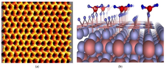
Figure 5. (a) Scanning probe microscopy image of graphene, (b) pseudocapacitance surface of RuO2 cathode [126].
Although most of the studies are focused on electrode materials of electrolytes, there are also significant studies on SC performance. The electrolyte consists of a solvent and dissolved chemicals that makes it electrically conductive and increases the quantity of ions in the electrolyte [9,106]. Electrolytes influence the operational voltage window of cells and their resistance [114]. Aqueous, organic, and ionic liquid electrolytes are currently available for SCs [94]. The electrolyte determines the SC’s operating characteristics [127]. Water is a perfect solvent for inorganic chemicals and aqueous electrolytes. Aqueous electrolytes are used in SCs with high specific power and low specific energy density, which have a 1.15 V dissociation voltage per electrode [106,128]. Electrolytes with organic solvents have a higher separation voltage and a temperature range; however, they are more expensive [106,128,129]. Ionic electrolytes consist of liquid salts, and they enable capacitor voltages above 3.5 V s. In addition, they have lower ionic conductivity than the other electrolytes [40].
Although much progress has been made in improving the electrode performance, in SCs, separators can negatively influence the performance of SCs to depend on the poorly designed dividers [9]. The separator can be very thin and must be very porous to minimise ESR. Developed polymer-based separators with low cost, high flexibility, and porosity lead the separator markets [41,94,106,130]. The majority of energy storage devices require collectors to connect the capacitor electrodes and supplement the performance of SCs, because of the active material’s insufficient conductivity. Additionally, they must carry high charge and discharge currents [94,106,131]. Sealing in cell mounting is very important to prevent performance loss in the SC. Aluminium metal should be used in collectors to prevent a corrosive galvanic cell housing [9,106]. A sealant material’s duty is to prevent foreign contaminants from entering the cell that can cause electrolyte disruption, surface oxidation, and the loss of life cycle [94].
3. Applications of SC
The SC has many advantages in applications with a high power density, and many charge/discharge cycles or a longer life are required. SCs are used in wind turbines, mobile base stations, electronic devices, and different industrial practices [135,136,137]. In addition, they have started to be used in UPS, electric vehicles, and various power electronics applications, thanks to their superiority over lead-acid batteries [138,139,140,141]. In recent years, SCs have been used as an energy storage device for voltage stability in renewable and hybrid energy storage systems to regulate the source and grid [3,10,141]. SCs can stabilise the power supply in applications with fluctuating loads [142]. SCs deliver power for flashes, which can be charged quickly [62,143], and portable speakers [144]. Reducing energy consumption and CO2 emissions is a primary difficulty of all transportation systems, and braking energy recovery can reduce both. Many applications in all kinds of vehicles require elements that can rapidly store and deliver energy, and SCs fulfil these requirements. Some SC applications include consumer electronics [62,63], tools, power supply [64], voltage stabilisation [65], microgrid [66], renewable energy storage [3], energy harvesting [67,68], street lights [69], medical applications [70], military and automotive applications [71,72,73], and energy recovery [74,75,76,77]. Some of these examples are given in Figure 8.
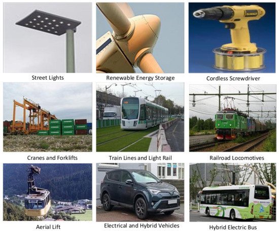
Figure 8. Some examples of SC applications.
Multiple variable loads, such as hybrid electrical vehicles (HEVs), electrical vehicle (EV) charge stations, electrical machines, and other power systems, cause current fluctuations and harmonics and power oscillations on the grid [63,64]. SCs can be used between the load and the grid as an interface to overcome these problems [145]. One wireless screwdriver with SCs is charged fully in 90 s, and it can retain 85% of its charged energy after three months left idle [146]. The backup power for actuators in wind turbine pitch systems is also provided by SCs [144]. Photovoltaic and wind energy systems act as a fluctuating supply induced by weather conditions. SCs can stabilise such as voltage fluctuations for power lines by acting as dampeners [66]. SCs can be used for microgrid storage, usually powered by renewable energy which cannot instantaneously match the demand to inject power when the demand increases and the production decreases temporarily [68,147]. SCs are suitable energy harvesting systems for temporary energy storage devices [3]. For example, in Japan’s Niigata Prefecture, Sado City, there are streetlights that combine stand-alone SCs with s power source for storage [69].
Hybrid SCs are also implemented in navigators, sensors, and communication devices based on batteries. The radar system, electromagnetic pulse weapons, torpedoes, etc., can also be operated using a suitable installation of hybrid SCs [148]. Many SC systems for military applications are manufactured by the Tecate Group corporation, as shown in Figure 9 [148]. The radar antenna, airbag exploitation power, avionics, GPS, and missiles are applications that require a high specific power [28].
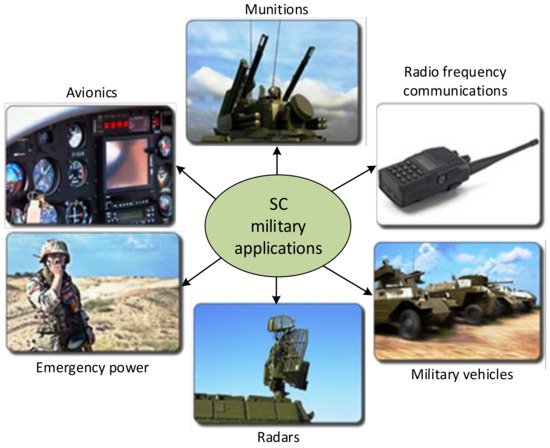
Figure 9. SCs used for different defence applications.
SCs also fulfil the requirements for some transportation applications, which are given here. Toyota’s Yaris hybrid-R concept car and Peugeot Société Anonymes (PSAs) Peugeot Citroën both use an SC to increase the performance of the vehicles [149]. The Maxwell Technologies manufacturer corporation claimed that several hybrid buses use SC devices to improve acceleration [149]. Batteries can be supplemented with SCs in the starter systems of diesel railroad locomotives with hybrid transmissions [71]. Mobile hybrid rubber tyre gantry cranes use SCs to move stack containers [70]. One hybrid forklift primarily uses fuel cells and batteries, while SCs store the braking energy of buffer power peaks. In 2003, a light-rail vehicle prototype was developed with a roof-mounted SC unit to save braking energy and replace overhead lines in Mannheim [72]. The Paris T3 tram line and Geneva Public Transport tram were powered using SCs to recover the energy during braking in 2012 [150].
The first hybrid bus in Europa with SCs was the so-called “Ultracap Bus” tested in Nuremberg, Germany, in 2001. Then, an electric bus fleet was tested in Luzern, Switzerland, in 2002. After every transportation cycle, the SCs could be recharged within 3 to 4 min with a high-speed power charger [151]. A new type of electric bus using SCs, called the “Capabus”, that moves without power lines and fully charges at the last terminal was tested in Shanghai in 2005 [75]. A Toyota hybrid racing car used a hybrid drivetrain with SCs that was developed every year [152]. More researchers have explored hybrid electric vehicles (HEVs) [153,154]. The ability of SCs to charge much faster than batteries, their longer lifetime, stable electrical properties, and wide temperature range make them suitable for electric vehicles. However, SCs’ lower specific energy density makes them unsuitable for long-distance driving as a stand-alone energy source [77]. As of 2013, all EV or HEV automotive manufacturers have developed prototypes to improve driveline efficiency and store braking energy that use SCs instead of batteries [152,155]. Today’s HEV technology has used SCs to develop more topologies using power electronics converters to increase the efficiency of EVs, improve the environmental perspective, and lower cost. [156,157].
An HEV uses different energy sources, including batteries, SCs, and fuel cells (FCs), to power the electric drive system, as seen in Figure 10a. A fraction of the energy exchange capability of the SC can be used in a battery/SC configuration only. Therefore, a hybrid fuel cell/battery/SC configuration still provides the most extended lifetime of the batteries [158,159]. As a solution, a forklift truck project was carried out with a 16 kW power hybrid system, as shown in Figure 10b. An ‘Integrated Fuel Cell Hybrid Test Platform in Electric Forklift’ designed in the Technical Research Centre of Finland Ltd. (VTT) consisted of an 8 kW power proton exchange membrane (PEM) type fuel cell, which provided 72 kW of power to Maxwell BOOSTCAP® (165F, 48 V) SCs and 300 Ah lead-acid batteries [160,161]. Another study reviewed energy systems for light-duty vehicles, and highlighted the main characteristics of electric and hybrid cars based on power train structure. Different topologies and energy management strategies for electric and hybrid vehicle powertrains have been investigated [162,163].
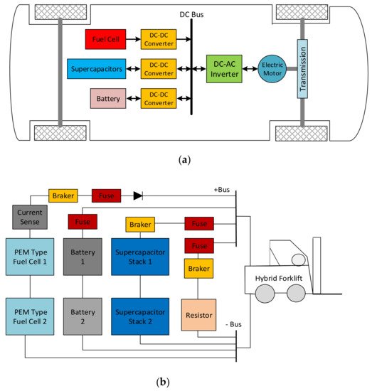
Figure 10. (a) A basic HEV drive system. (b) Hybrid forklift power source DC schema with two SC modules [160].
The comparison of SCs with the other energy storage devices has been investigated for PV–battery–SC systems in the literature, and has been shown that SCs have some advantages [14,42,43,46,47,48]. In addition, PV–battery–SCs or fuel cell combinations as HESSs are suggested as an alternative solution [49,50]. The HESS topologies include passive, active, and semi-active types. A passive HESS consists of the different energy storage devices connected directly to the DC bus without a DC–DC converter. If one side is combined with a DC–DC converter to a DC bus, it is called a semi-active HESS. If two sides of the energy storage devices are connected with converters, it is called an active HESS. The connection topology of HESSs is given in Figure 11a [3,12,43]. The active and passive HESSs were simulated and compared in a case study. While the SC semi-active HESSs performed with lower than 33% battery life, passive HESSs performed with lower than 9% battery life, only in the case of price function results during a day [3,12,43]. In another study, solar irradiance and temperature data were used for a solar farm model in MATLAB/Simulink from four diverse days from the 2017 simulation to define the annual storage cost, and the results showed that the battery + SC HESS cost was 25% cheaper annually [51]. In another study, a passive HESS was proposed for a wind and solar energy stand-alone system and the operation was tested via theoretical simulation and experimentally. The HESS (battery–supercapacitor) for the wind and solar energy-fed basic structure is shown in Figure 11b [164].
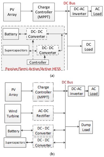
Figure 11. (a) A stand-alone active HESS with SC. (b) A HESS for a wind-solar fed system.
Several studies have presented comprehensive reviews of HESS control strategies for power quality improvement in microgrids in the last decade [132]. The increasing use of renewable energy sources and the interruption of the power generated has caused stability, reliability, and power quality problems in the primary electrical grid [165]. The microgrid is very sensitive to load or generation changes, as it is a weak electrical grid, and HESSs are used to decrease the effect of these variations [166]. Battery–supercapacitor HESSs in stand-alone DC microgrids have been reviewed, and a stand-alone photovoltaic-based microgrid with an HESS was presented as a case study [12]. A survey of a battery–supercapacitor HESS for a stand-alone PV power system in rural electrification was presented in a study [167]. A design and performance analysis of a stand-alone PV system with an HESS is given in another survey for a rural area of India. Bidirectional DC to DC converters are also used in controlling, with a fuzzy logic controller as a new control algorithm, as shown in Figure 12 [168].
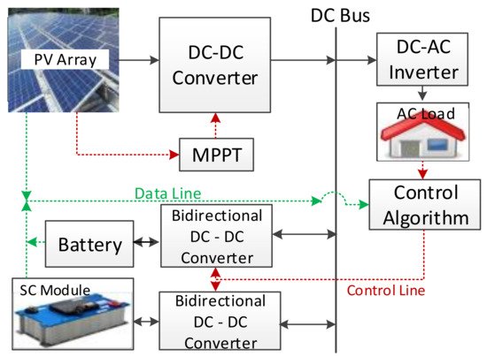
Figure 12. A sample PV-HESS microgrid system structure for domestic application [168].
5. Modelling and Performance Tests for SCs
The applied voltage to the poles is linearly proportional to the amount of electric charge stored in an SC, which has units of Farads. The voltage distribution among the SC and its simplified equivalent DC circuit model is seen in Figure 13a, as a functionality illustration of an SC. The electrode’s equivalent circuit depends on the porous structure’s capacitance behaviour, and is defined with series and parallel connected RC elements. The voltage behaviour of SCs and batteries differs during charge and discharge intervals, as seen in Figure 13b. The energy is stored in a static electric field in conventional capacitors consisting of two electrodes. The total power increases linearly related to the potential between the plates and the accumulated charges. In contrast, SCs consists of two electrodes separated by a separator and the energy stored inside the double layers of both electrodes. The storage of electrostatic and electrochemical energy in SCs is linear concerning the stored energy charge similarly [106].
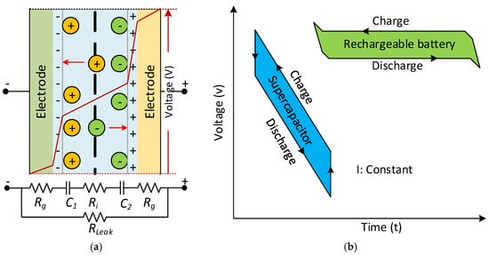
Figure 13. (a) The voltage distribution among the SC between simplified equivalent DC circuits. (b) Comparison of SC and battery voltage behaviour during the charge and discharge time.
The SC modelling and charge–discharge characteristics must be investigated differently from conventional storage devices. The capacitance value of an SC can be defined with RC components and time constants, depending on the frequency. The measurement characteristic for measuring capacitance is shown in Figure 14a. The rated voltage has to be applied to charge the capacitor for measurement firstly, and the SC is charged for 30 min. Next, the SC is discharged with a constant discharge current (Idischarge) [169]. Then, for the voltage drop from 80% (V1) to 40% (V2) of the rated voltage at the t1 and t2 time values is measured, and the capacitance value of the SC is calculated from this Equation (C=IΔtΔv) [106,170]. The internal DC resistance (Ri) of an SC can be calculated with the voltage drop (ΔV2) obtained from the intersection of the auxiliary line extended from the straight part and from the time base at the time of discharge start, as shown in Figure 14b [29,169].
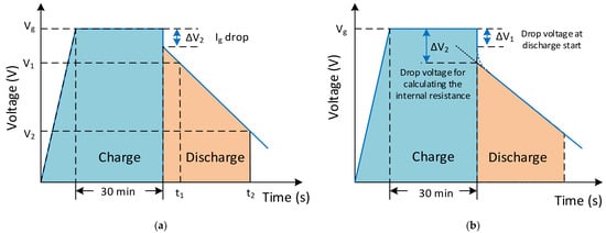
Figure 14. The charge–discharge characteristics for (a) measuring the capacitance and (b) internal DC resistance measurement conditions.
For SC systems, modelling is necessary for system dimension monitoring conditions. Chemical, mathematical, and electrical characteristics, ageing, artificial intelligence, and the dynamic structure of SC models are available in the literature [80,81,82,83,84,85,86,90]. To describe the behaviour of SCs, a simple electrical model of SCs has also been given in the literature [91]. The module simulation was based on a two-branched SC circuit model [89,90,91,92]. This circuit was simplified for the SC module and is given in Equation (4). The SC module voltage and currents are USC and ISC, and the primary voltage and currents are vsc and isc, respectively [89].
(4)
Moreover, it considered the equivalent electric circuit with two RC branches proposed by Zubieta and Bonert [90] and Rafik et al. [91]. The calculation used to obtain the relationship between voltage (v1) and capacitor charge (Q1) is seen in Equation (5), and can be combined with Equation (4) as in Equation (6).
(5)
(6)
An SC module model was designed in MATLAB/Simulink using these equations, as seen in Figure 15a. Equations (5) and (6) were revised for 310 F SC parameters obtained and calculated in experimental result values and datasheets from previous studies in the simulation [52]. The SC model was simulated for cycle life, and Capacitor ESR measurement waveforms in the datasheet were checked; the results are presented in Figure 15b [102,169].
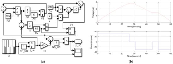
Figure 15. (a) SC module model in MATLAB/Simulink. (b) CAP/ESR waveforms of SC [169].
Higher source voltages are required when connecting SCs in series. Each component has a slight difference in capacitance value and ESR. Therefore, it is needed to actively or passively balance the SC to balance the applied voltage. Although passive balancing in SCs is supplied with parallel resistors, active balancing includes electronic voltage management that varies the current above a threshold. Active techniques have many advantages over passive methods. In contrast, passive strategies are straightforward, and despite their shortcomings, they are still prevalent, as shown in Figure 16 [171]. However, passive balancing with resistors improves voltage distribution in SCs, because extra currents passing through balancing resistors reduces the energy efficiency of SCs in their application as energy storage devices. The use of circuits has been proposed for active voltage balancing in SCs [61]. Although the load current and cycle stability of SCs are higher than that of rechargeable batteries, the SC life and the number of cycles increase with the lower load current [165].
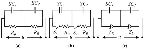
Figure 16. SC voltage balance (a) resistor, (b) switched resistor, (c) Zener diode circuits.
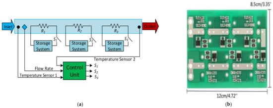
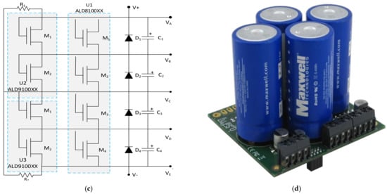
It is possible to find some products on the market for special rates and offers, and the customers can mount them to reduce the prices. An active voltage balancing SC-assisted surge absorber (SCASA) was developed using a recently patented technique [172]. This patent-pending technique uses an SC-assisted temperature modification apparatus (SCATMA), as shown in Figure 17a. This technique is based on the availability of large EDLC devices with capacitances in the range of 1200–5000 F, shallow ESR values, short circuit current capability in the field of 600–2400 A, and per cell energy storage capabilities in the capacity of 0.6–3 Wh [30]. A six-string supercapacitor protection board used for the module design is shown in Figure 17b [173]. A circuit diagram of the protection board for four capacitors’ balanced storage is shown in Figure 17c. Each SC can have a single metal oxide semiconductor field effect transistor (MOSFET) or two devices in parallel, connected depending on the selected board. An equivalent MOSFET gives twice the output current and twice the sensitivity to voltage change, connecting two devices in parallel [60]. An example commercial product for the SC module for a modular solution with UPS and advanced technology extended (ATX) power modules is seen in Figure 17d [174].
This entry is adapted from the peer-reviewed paper 10.3390/en15030674
This entry is offline, you can click here to edit this entry!