High-speed electrical machines have been extensively researched in the last few decades for industrial and domestic applications, including compressors, vacuum pumps, turbine generators, machine tools, flywheel energy storages, and so on. Compared with low-speed and moderate-speed conventional electrical machines, high-speed electrical machines offer advantages such as high-power density, small size, and light weight. More importantly, high-speed electrical machines can be directly connected to high-speed loads, and conventional gear boxes are no longer needed, which avoids complex gear box systems, improves system efficiency and reliability, and reduces system vibration, noise, and cost. With the evolution in the field of power electronics converters, the problems of high frequency supplies, required for high-speed operation, is no longer a restriction. The development of high-speed electrical machines is also supported by the development of high-speed bearing systems with high robustness, fewer losses, and longer lifetime.
- high-speed
- permanent magnet machine
- rotor constructions
- stator structures
- three-phase
- winding configurations
1. Introduction
2. Single-Phase and Three-Phase PM Machines
2.1. Single-Phase
2.2. Three-Phase
2.3. Summary
| Advantages | Disadvantages | |
|---|---|---|
| Single-phase PM machine |
|
|
| Three-phase PM machine |
|
|
3. Stator Structures and Winding Configurations
In this section, the stator structures and winding configurations of HSPM machines are overviewed. The stator structures can be classified into slotted and slotless topologies, and the winding configurations can be divided into overlapping and non-overlapping layouts. The outline is illustrated in Figure 7.
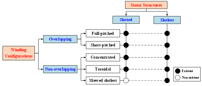
Figure 7. Outline of stator structures and winding configurations.
3.1. Stator Structure
3.1.1. Slotted
In general, the stator structures of slotted HSPM machines can be separated into multi-slot (>6-slot) and minimal-slot (6-slot; 3-slot) [27], Figure 8. The multi-slot stator structure is widely used for high power (>10 kW) requirements.
Reference [30] designs a 48-slot/8-pole HSPM machine with a rating of 2 MW at 20 krpm by multi-physics and multi-objective optimization. The optimal goal is the maximum torque per loss per mass, with a trade-off between power density and efficiency. For aircraft turbo-generator applications, the 36-slot/4-pole machine topology is employed for two HSPM machines, and their rated powers and speeds are 150 kW at 17 krpm [32] and 100 kW at 60 krpm [33]. Ref. [32] mainly analyses the various loss components, and [33] focuses on thermal analysis by the finite element method (FEM). With toroidal windings, a 36-slot/2-pole HSPM machine [34] and three 24-slot/2-pole HSPM machines are designed and analyzed, including various loss components, mechanical stress, temperature distributions, and rotor dynamics [35,36,37]. In [38,39,40,41], 18-slot/2-pole HSPM machines are researched for different applications, such as electric vehicles and electric-turbo compounding systems. In addition, 12-slot/2-pole HSPM machines are employed in industrial applications [42,43,44,45]. For centrifugal turbo-compressors, a 50 kW, 70 krpm 12-slot/2-pole HSPM machine is designed and analyzed by an analytical approach [42]. Ref. [43] investigates the influence of sleeve thickness on the rotor eddy current loss, von-Mises stress, unbalance vibration response, and critical speed in a 15 kW, 120 krpm 12-slot/2-pole HSPM machine for air blower cooling fuel cells. Then, [44] proposes a 3 kW 100 krpm 12-slot/2-pole HSPM machine for electric turbochargers, and the influence of the rotor length/diameter (L/D) ratio on the response time is analyzed.
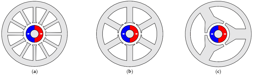
Figure 8. HSPM machines with multi-slot and minimal-slot stator structures. (a) Multi-slot (12-slot). (b) Minimal-slot (6-slot). (c) Minimal-slot (3-slot).
Overall, for various applications and requirements, the slot number should be optimized for different optimization objectives in the design of high-speed HSPM machines. [46] investigates the influence of slot/pole number combination on the performances in high-power HSPM machines, including 12-/24-/27-/36-slot and 2-/4-pole. The results show that compared with the machine with a 2-pole rotor, the machine with a 4-pole rotor has larger stator iron loss but smaller copper loss due to shorter end-winding length. In addition, the 4-pole rotor can reduce the machine axial length and improve the rotor dynamic characteristics. With the 4-pole rotor structure, the influence of slot number on the cogging torque and PM eddy current loss is investigated, and the 27-slot is selected due to the lowest cogging torque and small PM eddy current loss.
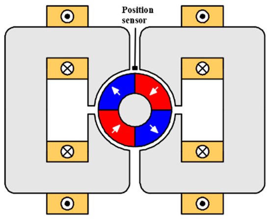
For low-power HSPM machines, the minimal-slot stator structure is employed to simplify the winding process and avoid the physical limitations of the small size. In the literature, three typical slot/pole number combinations are selected in low-power small-size HSPM machines, i.e., 6-slot/4-pole, 6-slot/2-pole, and 3-slot/2-pole, Figure 9, which will be reviewed as follows.
6-slot/4-pole
As mentioned before, the 4-pole rotor is adopted to reduce the end-winding length, copper loss, and stator yoke thickness in several multi-slot HSPM machines [46,47,48]. With the same design considerations, a 4-pole rotor is selected for 6-slot HSPM machines [49,50,51,52]. Ref. [49] designs a 3 kW 80 krpm 6-slot/4-pole HSPM machine with concentrated windings for generators. The tooth shoe shape is optimized to minimize the eddy current loss in the rotor sleeve and increase the efficiency. Ref. [51] investigates the optimal split ratio of 6-slot/4-pole HSPM machines considering stator iron loss and mechanical constraints. In [52], the 6-slot/4-pole and 6-slot/2-pole HSPM machines with a rating of 2.5 kW at 100 krpm are compared to enhance output power density. With the same loss density, cooling capability, packing factor, and machine axial length (including end-winding), the 4-pole machine can increase the output power density by 1.5 whilst at the same time decreasing the machine size by 33% (stator outer diameter), when compared with the 2-pole machine. However, this research neglects the switching loss in the power electronics converter, which has a close relationship with fundamental frequency, this is doubled for the 4 pole machine and should be considered.

Figure 9. Low-power small-size HSPM machine topologies with minimal-slot stator structures. (a) 6-slot/4-pole. (b) 6-slot/2-pole with straight teeth. (c) 6-slot/2-pole with semi-closed. (d) 3-slot/2-pole.
6-slot/2-pole
For low-power, small-size HSPM machines, the frequency of the 4-pole machine is twice that of the 2-pole machine, which leads to larger stator iron losses and switching losses in the power electronic converters. More importantly, for ultra-high-speed operation, 2-pole magnets can be designed as a magnet ring or a solid PM, which have high mechanical strength and simple manufacturing processes. Therefore, the 2-pole rotor is widely employed in low-power, small-size HSPM machines [24,27,53-66].
Ref. [27] analyses several design features of high-speed PM machines for microturbines, including stator structures, winding configurations, rotor constructions, and bearing systems. It shows that compared with the multi-slot structure, the 6-slot/2-pole machine with full-pitched overlapping windings has the largest winding factor, i.e., ‘1’. [24] designs a 5 kW 240 krpm 6-slot/2-pole ultra-high-speed PM machine with concentrated windings. The Inconel-718 sleeve is employed to protect the rotor, and the magnet rings are magnetized radially. Although the winding factor decreases from ‘1’ to ‘0.5’ due to the concentrated winding, the reduced end-winding axial length leads to the decreased machine axial length and improved rotor dynamic characteristic. In [53], for turbocharger applications, the 6-slot/2-pole and 3-slot/2-pole number combinations are compared for a 2 kW HSPM machine with a rated speed of 120 krpm and the maximum speed of 220 krpm. According to the loss analysis, the 6-slot machine with significantly smaller overall machine losses is more suitable for high-speed applications. Therefore, [55,56] design a 6-slot/2-pole 1.5 kW 150 krpm HSPM machine with parallel magnetized magnets for automotive superchargers; ‘b’-shaped easily manufactured copper-bar windings are employed. [57] analyses the eddy current losses in copper-bar windings due to proximity effect caused by high-speed operation and reduce the AC copper losses by different tooth-tip shapes and segmentation of the conductors.
In [62], for compressor applications, a 3 kW, 80 krpm 6-slot/2-pole HSPM machine is optimized for the highest efficiency by FEM. Then, for a 15 kW 150 krpm electrically assisted turbocharger, [63] designs two high-speed PM machine topologies: a 6-slot/2-pole machine with straight teeth, Figure 9a, and a 6-slot/2-pole machine with semi-closed slots, Figure 9b. It shows that the 6-slot/2-pole slotted machines have a good compromise between efficiency and torque. More importantly, in terms of rotor dynamic conditions, the 6-slot/2-pole machine with semi-closed slots is the better choice due to the shorter machine axial length. Researchers in [61] designed two 6-slot/2-pole HSPM machines with a rating of 11 kW at 31.2 krpm for gas blower applications and 3.5 kW at 45 krpm for micro-organic Rankine cycle power plants. A multidisciplinary design process is proposed, and it indicates that considering the constraints of electromagnetic, mechanical, thermal, and dynamic, the design of high-speed machines cannot have a single optimum solution but can have different solutions for different requirements.
3-slot/2-pole
3-slot/2-pole number combination is the simplest structure for three-phase slotted high-speed PM machines. [26] designs a 3-slot/2-pole 10 W 150 krpm HSPM machine for a precision handpiece (or hand-tool) and analyses several challenges and constraints of high-speed operation. [21] designs a 1.3 kW 20 krpm HSPM machine for a friction welding unit, and the stator iron loss is analyzed under different maximum stator iron flux densities and lamination materials. In [67], considering the sensorless operation based on the detection of the zero-crossing of the back-EMF waveform, the design criteria of a 1.26 kW 120 krpm 3-slot/2-pole HSPM machine is investigated. It shows that under the same overall size (including end-winding) and the similar efficiency, a machine with a lower stator iron flux density has smaller inductances and lower diode conduction angles and is therefore more suitable for high-speed sensorless operation. In [68], a 3-slot/2-pole HSPM machine is optimized by FEM for maximum efficiency considering stator iron loss. [69] analyses and designs two 1.0 kW, 2-pole HSPM machines with a speed range of 20–40 krpm. One is a 3-slot/2-pole slotted HSPM machine, and the other is a 2-pole slotless HSPM machine. In [1], based on the 3-slot/2-pole slotted and 2-pole slotless machines, the potentials and limits of low-power HSPM machines are discussed in terms of electromagnetic, mechanical, and thermal aspects.
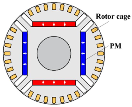
However, compared with the 6-slot/2-pole, the 3-slot/2-pole machines have inherent UMF due to the diametrically asymmetric stator structure. In [70], the influence of machine dimensions on no-load UMF is investigated, and a method of reducing no-load UMF is proposed, this adds extra notches in the middle of each stator tooth, . Then, in [71,72], the position and size of extra notches are optimized to reduce the no-load and on-load UMFs, Figure 10b, and rotor eddy current losses of 3-slot/2-pole PM machines, respectively, Figure 10c. They show that the optimized extra notches almost eliminate the rated on-load UMF and significantly reduce the rotor losses. However, the elimination and reduction highly depend on load conditions, and the output torque is decreased slightly.
The rotor eccentricity due to manufacturing tolerances not only significantly increases the UMF but also affects the electromagnetic performances of the 6-slot/2-pole and 3-slot/2-pole PM machines, including open-circuit air-gap field, back-EMF, cogging torque, electromagnetic torque, etc. [73] investigates the influence of static and dynamic rotor eccentricities on the electromagnetic performance of 3-slot/2-pole PM machines considering eccentricity ratio, eccentricity angle, and rotor initial angle. It shows that static rotor eccentricity leads to unbalanced magnitudes and phase angles of fundamental back-EMFs of the three phases but does not change the harmonic content. For dynamic rotor eccentricity, three phase back-EMFs remain balanced, but exhibit asymmetric positive and negative half-periods in the phase back-EMF waveforms depending on the eccentricity angle and the rotor initial angle. The largest asymmetric back-EMF waveform occurs when the angle difference between the eccentricity angle and the rotor initial angle is 90 electrical degrees. Compared with static rotor eccentricity, the dynamic rotor eccentricity has almost the same average torque and UMF but larger torque ripple and peak cogging torque. Two kinds of manufacturing tolerances, stator core gap and misalignment due to modular design also affect the electromagnetic performance of 6-slot/2-pole HSPM machines with toroidal windings [74], especially for the fundamental magnitudes and phase angles of the three-phase back-EMFs, cogging torque, and torque ripple.
Optimal Design of Slotted Machines
As mentioned before, there is no single optimum design with multidisciplinary designs and thus this section mainly shows the optimal design in terms of electromagnetic performance.
For slotted stator structure, the split ratio, i.e., the ratio of stator inner diameter to outer diameter, is an important factor for machine design since it has a close relationship with the torque capability and efficiency [21,26,75]. For the maximum torque, the optimal split ratio depends on the remanence of the magnet (Br) and the maximum stator iron flux density (Bmax) [21]. For the maximum efficiency considering the stator iron loss, the optimal split ratio depends on the stator active length, output torque, and Bmax [68]. This also shows that the stator iron loss considered decreases the optimal split ratio. Researchers from [69] focus on two design variables for the maximum torque, the stator inner diameter and the open circuit maximum stator iron flux density. With a fixed stator outer diameter, the first design variable is equivalent to the split ratio. In addition, the stator thermal limitation is introduced to avoid the thermal issues of the stator, which means that the sum of stator copper loss and iron loss is restricted. Considering the stator iron loss and mechanical constraints, [51] investigates the optimal split ratio of a 6-slot/4-pole HSPM machine for maximum torque considering the influence of air-gap length and rotor pole pairs. The results show that the mechanical constraints considered decrease the optimal split ratio. The limitations of stator total loss and rotor eddy current losses are taken into account in [65] since the rotor losses in small-size HSPM machines are difficult to reduce, and the cooling capability of the rotor is relatively poor. In [66], three 6-slot/2-pole HSPM machines with 1, 2, and 3 slot-pitch windings are optimized by FEM considering the influence of armature reaction on the stator iron loss. The stator iron loss increases with the increase of coil-pitch due to the increased magnitudes of stator magnetomotive force (MMF) spatial harmonics.
For the minimum torque ripple and maximum efficiency, considering the stator iron loss, copper loss, and rotor eddy current losses, a ‘Tanguchi’ method is used in [76]. The ‘Tanguchi’ method is a simplified version of the global optimization, and different design variables with different suitable variation ranges are adopted. This method can avoid the calculation of maximum stator iron flux density.
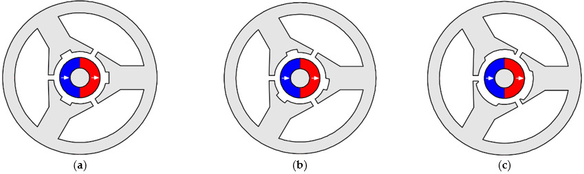
Figure 10. Extra notches for reducing no-load UMF, on-load UMF, and rotor eddy current loss. (a) Extra notches for reducing no-load UMF [70]. (b) Extra notches for reducing on-load UMF [71]. (c) Extra notches for reducing eddy current loss [72].
3.1.2. Slotless
The slotless stator structures with large airgaps and flux leakages have relatively small output torque, and are rarely used for conventional low-speed and moderate-speed PM machines. For high-power, large-size HSPM machines, although the high speed can increase the power, the critical speed is limited by the rotor mechanical strength and dynamic characteristics. Therefore, a relatively large torque is required for these machines; therefore, the slotless stator structure is not a suitable choice. For low-power, small-size HSPM machines, the critical speed is higher than that of high-power, large-size HSPM machines due to smaller rotor diameter. Therefore, the slotless stator structures with relatively small torque can be accepted in low-power, small-size HSPM machines, Figure 11.
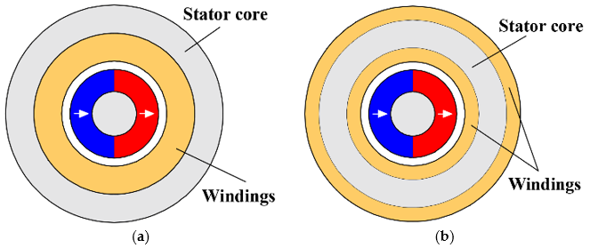
Figure 11. Slotless high-speed PM machines. (a) Air-gap windings. (b) Toroidal windings.
Ref. [77] proposes a 2-pole slotless PM machine for speeds in excess of 100 krpm, and it is compared with a slotted HSPM machine with the same external size. The analysis shows that the slotless stator structure with a simple construction is extremely attractive, especially for ultra-high-speed operation. Toroidal windings are employed in this slotless machine. In [27], multi-slot, minimal-slot, and slotless machines are discussed. It shows that compared with the slotted machine, the slotless machine has a smaller open-circuit air-gap flux density due to larger flux leakage and lower rotor loss due to the uniform air gap. To compensate for the reduction of flux density, the stator active length of the slotless machine is relatively long.
The comparison in [27,77] mainly focuses on electromagnetic performance. However, in [1,69], the comparison of a 3-slot/2-pole slotted HSPM machine and a 2-pole slotless HSPM machine includes electromagnetic performance, temperature distribution, mechanical stress, and PM demagnetization. The results show that for slotless machines, the effect of armature reaction is restricted, and the PM demagnetization is avoided due to the reduced rotor eddy current loss. [50] compares a 6-slot/4-pole HSPM machine and a 2-pole slotless machine for the reduction of noise emissions. It shows that the slotless machine has 38% smaller open-circuit power loss and 12 dB lower noise due to significantly less armature reaction.
In the literature, it can be seen that the slotless stator structure is popular for ultra-high-speed applications due to its simple structure and no teeth [50]. Example applications are: a 1200 krpm microsize machine [31], a 1000 krpm starter for a gas turbine [78], a 500 krpm mesoscale gas turbine [28,79], a 400 krpm centrifugal compressor [80,81]. Most importantly, the slotless stator may be the only solution for micro-scale HSPM machines. [82] presents a millimeter-scale 2-pole slotless bearingless HSPM machine with a rated speed of 160 krpm for electrical drive systems. The measured overall machine losses at 160 krpm are below 1 W and the measured temperature is below 45 °C.
2-pole slotless ultra-high-speed PM machines are designed and optimized for minimum power losses by analytical methods in [79,80], and [83]. However, the constraints used are different, namely, the maximum stator iron flux density in [79], the maximum allowed current density in [80], and the dimensions of the rotor in [83].
3.1.3. Summary of Stator Structures
In this section, the applications, advantages, and disadvantages of slotted and slotless stator structures are summarised in Table 2. The selection of slotted and slotless stator structures usually depends on the design requirements. The slotted stator structure is suitable for the requirement of large output torque, and the slotless stator structure is a better choice for the requirements of low rotor loss and micro-size machine dimension.
Table 2. Applications, advantages, and disadvantages of slotted and slotless stator structures.
|
|
Slotted |
Slotless |
|
Application |
|
|
|
Advantages |
|
|
|
Disadvantages |
|
|
3.2. Winding Configuration
With slotted and slotless stator structures, various winding configurations can be combined for different applications. In general, the winding configuration can be divided into overlapping and non-overlapping windings, which have a close relationship with the winding factor, end-winding length, and machine axial length.
3.2.1. Overlapping Winding
For machines with integral, overlapping windings include full-pitched and short-pitched versions according to the coil span angle (θs), i.e., θs = π elec. deg. and θs ˂ π elec. deg., respectively. When the coil span angle is equal to the pole pitch, i.e., a full-pitched winding, the winding factor is ‘1’, and when the coil span angle is less than the pole pitch, i.e., a short-pitched winding, the winding factor is less than ‘1’.
Slotted Machine
In high-power multi-slot (˃6-slot) HSPM machines, full-pitched overlapping windings are widely employed, Figure 12a, [32,33,38,39,40,42,43,44,84,85,86,87]. Although the full-pitched overlapping winding has a long end-winding and axial length, the output torque is usually large since the winding factor is ‘1’.
In [88], a 36-slot/6-pole 30 kW 20 krpm high-speed IPM machine employs a 5/6 short-pitched overlapping winding to reduce the space harmonic components of MMF and minimize the rotor eddy current losses. However, the fundamental component and the output torque are slightly decreased due to the reduced winding factor, from 0.966 to 0.933. Researchers in [43,77] also employ 5/6 short-pitched windings for a 12-slot/2-pole HSPM machine to reduce the rotor loss, Figure 12b. [89] employs 4 slot-pitch windings, i.e., 4/12 short-pitched windings, for a 24-slot/2-pole HSPM machine to short the end-winding axial length and machine axial length, whose winding factor is only ‘0.48’.
For low-power minimal-slot HSPM machines, the full-pitched overlapping winding can only be used in 6-slot machines. However, the 6-slot/2-pole low-power small-size HSPM machine is sensitive to the end-winding axial length, and the full-pitched overlapping winding leads to long axial lengths, low torque density, and low rotor mechanical natural frequency. In [90], the 3-slot/2-pole HSPM machine with concentrated non-overlapping windings and two 6-slot/2-pole HSPM machines with full-pitched overlapping and concentrated non-overlapping windings are compared for the rotor eddy current loss. With sine-wave currents and unmagnetized magnets, i.e., only considering stator MMF space harmonics, the 3-slot/2-pole machine has the largest rotor eddy current loss, and two 6-slot/2-pole machines have almost the same rotor loss.
For 6-slot/2-pole HSPM machines, 3 slot-pitch (full-pitched) windings [27,90] and 1 slot-pitch (concentrated) windings [24,53,91] have been employed for high-speed applications, Figure 13a,d. [66] compares three 6-slot/2-pole HSPM with 1, 2, and 3 slot-pitch windings and the results indicate that 2 slot-pitch (short-pitched) windings, Figure 13b, are attractive for improving the power density due to relatively short end-winding axial length and relatively large winding factor, which is suitable for high-speed applications. In addition, the influence of end-winding on the torque and torque density with different stator active lengths is investigated. It shows that for relatively long stator active length, the machine with 2 slot-pitch windings has the largest torque, as well as the highest torque density. Furthermore, [92] designs two 6-slot/2-pole HSPM machines with different layouts of 2 slot-pitch windings, i.e., Machine A and Machine B, Figure 13b,c. It shows that, compared with Machine A, Machine B is an attractive machine design due to shorter axial length of end-winding, higher torque density, and smaller phase inductance. In addition, a conventional 3-slot/2-pole HSPM machine with non-overlapping windings is compared with the 6-slot/2-pole HSPM machine with 2 slot-pitch windings since they have the same winding factor, i.e., 0.866. The results show that compared with the 3-slot/2-pole HSPM machine, the 6-slot/2-pole HSPM machine with 2 slot-pitch windings has advantages of high torque, low rotor loss, no UMF, and small phase inductance, which are desirable for high-speed operation.
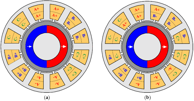
Figure 12. Full-pitched and short-pitched overlapping windings for 12-slot/2-pole HSPM machines. (a) Full-pitched. (b) 5/6 short-pitched.
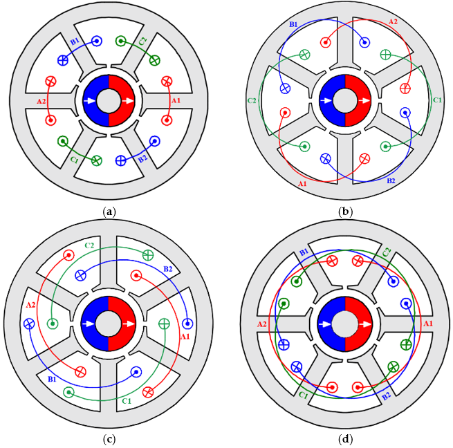
Figure 13. 6-slot/2-pole HSPMmachines with 1, 2, and 3 slot-pitch windings. (a) 1 slot-pitch winding. (b) 2 slot-pitch winding, MA. (c) 2 slot-pitch winding, MB. (d) 3 slot-pitch winding.
Slotless Machine
For slotless HSPM machines, the overlapping winding is widely employed since the large winding factor can compensate for the low flux linkage caused by large air-gap, Figure 14a, [1,69,81,93,94,95,96].
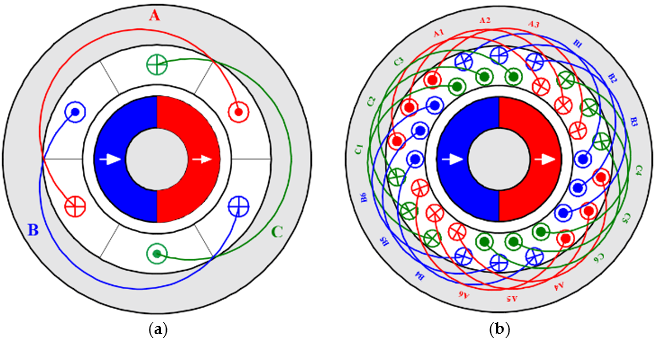
Figure 14. 2-pole slotless HSPM machines with full-pitched and short-pitched windings. (a) Full-pitched. (b) Short-pitched.
Ref. [93] compares the overlapping and non-overlapping windings for slotless PM brushless machines. It shows that the conventional overlapping windings can offer large power density and are more suitable for medium and large machines where the power density is an important criterion. However, it also points out that the overlapping windings may be difficult to wind, and their relatively long end-winding may not be acceptable for high-speed applications. Researchers in [94] design a 2-pole slotless HSPM machine for hand-tool applications. With full-pitched overlapping windings, the axial leakage is analyzed by a 2-D analytical model and a 3-D FE model. It shows that at the axial ends of the machine, the reduction of flux density is substantial, but that the reduction in back-EMF is minor due to the machine dimensions for hand-tool applications. In [79], a 100 W 500 krpm slotless HSPM machine adopts full-pitched overlapping windings, and its winding factor (kw) is calculated by

Compared with a slotted machine with full-pitched overlapping windings, for which kw = 1, the slotless machine with full-pitched overlapping windings has a relatively lower winding factor. However, although the full-pitched overlapping winding has a large winding factor, the long end-winding length and axial length may decrease the torque density, increase the copper loss, and reduce the rotor mechanical natural frequency. Therefore, the short-pitched overlapping winding with a relatively large winding factor and relatively short end-winding axial length is attractive for improving torque density. In [29,97], a 2-pole slotless ultra-high-speed PM machine with a rating of 2 kW at 200 krpm is designed for cryogenic compressor applications. The machine employs 15/18 short-pitched overlapping windings to reduce the end-winding length and copper loss, Figure 14b.
3.2.2. Non-Overlapping Winding
In this section, different non-overlapping winding configurations are discussed, including concentrated windings, toroidal windings, and skewed slotless windings.
Slotted Machine
In high-power multi-slot (˃6-slot) HSPM machines with 2-/4-pole rotors, the concentrated winding results in a low winding factor. Take 2-pole machines with 12-/18-/24-slot as examples. The fundamental winding factors of three machines with full-pitched overlapping windings are 0.966, 0.960, and 0.958, respectively, while those of three machines with concentrated windings are 0.5, 0.5, and 0.5, respectively. Therefore, the concentrated non-overlapping winding is not desirable for high-power multi-slot HSPM machines.
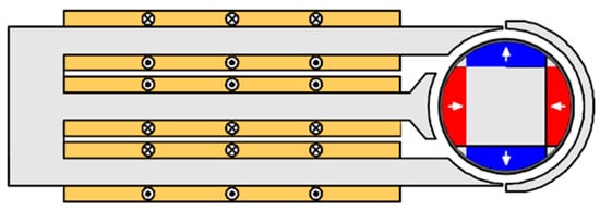
Compared with full-pitched overlapping windings, toroidal windings with the same winding factor have a shorter end-winding axial length, which improves the rotor stiffness and avoids rotor dynamic issues. More importantly, the airspace between the slots at the core back (Figure 15) can be used as cooling channels, increasing the machine cooling capability. These considerations have resulted in toroidal windings replacing overlapping windings in high-power multi-slot HSPM machines [35,36,37]. However, the outside conductors of toroidal windings do not produce back-EMF but are a part of the end-winding length and consequently increase the copper loss. In addition, the leakage flux caused by outside conductors leads to eddy current losses in the machine frame [98], which may account for about 50% of overall losses in a particular design and decrease the machine efficiency. Although the heat dissipation in the frame is not difficult to deal with, it needs attention in the design process.
In [37,99], the windage losses and anti-demagnetization of the 75 kW 60 krpm 24-slot/2-pole HSPM machine with toroidal windings are studied by 3D FEM, Figure 15. The predicted windage losses and rotor temperature are verified by the measured results. It also shows that the toroidal winding can reduce windage loss, which has a close relationship with the rotor axial length. [36] proposes a design method of HSPM machines considering electromagnetic performance, mechanical strength, rotor dynamic characteristics, and temperature distribution. Then, a 15 kW 30 krpm 24-slot/2-pole HSPM machine with toroidal windings is designed and prototyped. Researchers in [35] design a 24-slot/2-pole air-cooled HSPM machine with toroidal windings. The electromagnetic performance is analysed by a FEM model, and the thermal properties with air-cooling are analyzed by computational fluid dynamic (CFD) thermal model and LPTN model. By optimising the stator dimensions, especially the outer slot, the loss density is reduced, and the cooling capability is improved [100].
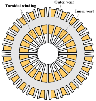
Figure 15. 24-slot/2-pole HSPM machine with toroidal windings [37].
Therefore, in multi-slot HSPM machines, toroidal windings are more suitable than concentrated non-overlapping windings. However, both toroidal windings [27,101,102] and concentrated windings [24,54–65,91] are widely used in 6-slot HSPM machines, Figure 16. [61] shows that although the fundamental winding factor of the concentrated winding is ‘0.5’, doubling the number of turns may not lead to large copper loss due to short end-winding compared with the full-pitched overlapping windings. In addition, with forced-air cooling, the outer slot not only supports the outer windings of toroidal windings but also can be the air-duct to improve the thermal dissipation capability.
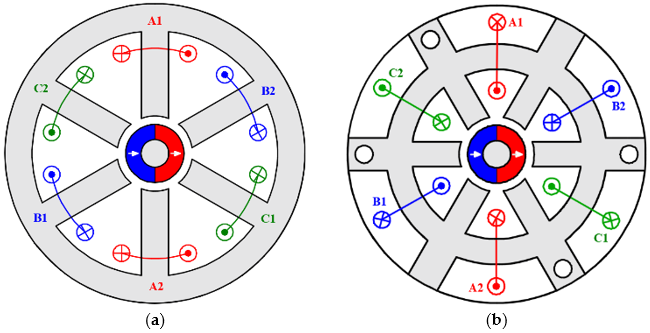
Figure 16. 6-slot/2-pole HSPM machines with concentrated and toroidal non-overlapping windings. (a) Concentrated winding. (b) Toroidal winding.
In 3-slot/2-pole HSPM machines, the concentrated winding is a conventional winding configuration [1,21,26,67,68,69,76,103], while the toroidal winding is rarely mentioned. [101] analyses the electromagnetic performance of 2-pole HSPM machines with toroidal windings and different slot numbers, including 3-slot, 6-slot, 9-slot, and 12-slot. It shows that the winding factor of the 3-slot/2-pole machine with toroidal windings is ‘0.5’, which is smaller than that of the 3-slot/2-pole machine with concentrated windings, ‘0.866’. In addition, the 3-slot/2-pole machine with toroidal windings cannot eliminate the 3rd harmonic in the flux linkage waveform caused by the associated 3rd air-gap field harmonic or local magnetic saturation. This results in a 3rd harmonic component in the phase back-EMF waveform. However, this will disappear in the line back-EMF waveform and it has no influence on the torque. Therefore, in 3-slot/2-pole HSPM machines, the concentrated winding is a better solution than the toroidal winding with a smaller winding factor.
Slotless Machine
In slotless machines, three non-overlapping winding configurations can be used [93,104], such as concentrated windings [80], toroidal windings [28,98], skewed slotless windings [105,106,107,108], Figure 17.
In [77], a multilayer basket winding, i.e., skewed slotless winding, and a ring winding, i.e., toroidal winding, are compared for a 50 W 150 krpm slotless HSPM machine. It shows that the skewed slotless winding has almost no end-windings and all conductors are in the air-gap and magnetic field caused by PMs, which means the winding axial length is almost the same as the stator active length. However, this kind of winding with a relatively complex structure requires specialist equipment and a special manufacturing process. In the literature, there are three skewed slotless winding configurations, i.e., helical windings, rhombic windings, and diamond windings, Figure 18, [105,106,107,108]. Ref. [109] investigates the 3D torques and forces of two skewed slotless winding configurations, i.e., helical windings and rhombic windings, and their potential for high-speed applications is also analyzed. For skewed slotless windings, three-phase coils are overlapped radially, which increases the winding thickness in the air-gap, but has almost no end-winding, reducing the machine axial length and increasing the rotor mechanical natural frequency. However, since the coil is skewed by π elec. deg., the current direction is not ideal and may lead to extra undesired transverse torque and force.
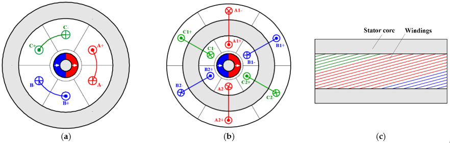
Figure 17. 2-pole slotless HSPM machines with different non-overlapping windings. (a) Concentrated winding. (b) Toroidal winding. (c) Skewed slotless winding.
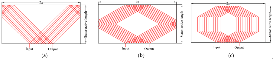
Figure 18. Phase A coils of three skewed slotless winding configurations [106,110]. (a) Helical. (b) Rhombic. (c) Diamond.
Ref. [110] investigates the influence of three slotless winding configurations, i.e., concentrated windings, toroidal windings, and helical windings, on the rotor eddy current loss of a 2-pole slotless HSPM machine by 2D and 3D analytical and FE models. The results show that, with the same power and phase current, the machine with concentrated windings has the highest rotor eddy current loss due to the 3-coil rotational asymmetric winding distribution, and the machines with helical and toroidal windings have almost the same low rotor eddy current loss. Although with higher rotor eddy current loss, the non-overlapping windings with 3 coils per 2 poles are employed in a 2-pole 400 krpm slotless HSPM machine due to their simplicity [80]. Refs. [93,104] review the winding topologies for slotless brushless permanent magnet machines and investigate the influence of winding topologies on the optimal design. They indicate that the winding configurations have small influence on the optimal ratio of magnet thickness to winding thickness for minimum copper loss, since the configuration only changes the coefficient in the calculation of copper loss. Several slotless machines with toroidal windings have been mentioned before and are widely employed in ultra-high-speed PM machines due to the simple winding process, short end-winding axial length, modular design, and improved cooling capability. Examples are 150 W at 1200 krpm in [31], 100 W at 500 krpm in [28], 150 W at 200 krpm in [98], 15 kW at 150 krpm in [63], and 160 krpm in [82].
3.2.3. Summary of Winding Configurations
In this section, the applications, advantages, and disadvantages of overlapping and non-overlapping are summarised in Table 3.
As mentioned before, the overlapping winding includes full-pitched and short-pitched windings, while the non-overlapping winding includes concentrated, toroidal, and skewed slotless windings. They have their own suitable stator structures and applications, which depend on the design requirements and machine dimensions.
- For high-power multi-slot HSPM machines, overlapping winding and toroidal non-overlapping winding are employed. The main difference between two winding configurations is the end-winding axial length;
- For low-power minimal-slot HSPM machines, the concentrated non-overlapping winding is a dominant winding configuration due to short end-winding axial length. Although it has a short end-winding axial length, the toroidal winding needs additional volume radially for the outside windings. These also produce eddy current losses in the frame.
- For slotless HSPM machines, both overlapping and non-overlapping windings are employed. Full-pitched overlapping windings with the largest winding factor can offer the maximum output torque; however, they have the longest end-winding axial length, while the short-pitched overlapping winding with a relatively small winding factor not only decreases the rotor losses but also improves the rotor mechanical stiffness.
- The toroidal non-overlapping winding with short end-winding axial length and the simple winding process is popular for slotless stator applications.
- The skewed slotless winding, i.e., helical, rhombic, and diamond windings, with compact structure, self-support construction, and no end-winding, is an attractive solution for slotless HSPM machines. However, the non-idealized skewed current direction leads to undesirable torque and force. In addition, the skewed slotless winding needs a 3D model to analyse and requires a special manufacturing process.
Table 3. Applications, advantages, and disadvantages of overlapping and non-overlapping windings.
|
|
Overlapping |
Non-Overlapping |
|||
|
Full-pitched |
Short-pitched |
Concentrated |
Toroidal |
Skewed |
|
|
Applications |
Multi-slot; Slotless |
Multi-slot; Slotless |
Multi-slot; Minimal-slot; Slotless |
Multi-slot; Minimal-slot; Slotless |
Slotless |
|
Advantages |
|
|
|
|
|
|
Disadvantages |
|
|
|
|
|
4. Rotor Structure
For high-speed applications, the PM machines mainly employ three different rotor structures, i.e., IPM, SPM, and solid PM, Figure 19. Those different rotor designs affect the electromagnetic performance, thermal aspect, mechanical strength, and dynamic characteristic of HSPM machines.
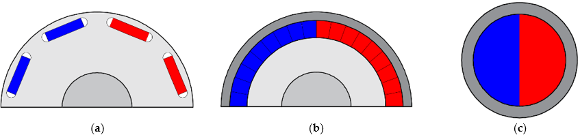
Figure 19. High-speed PM machines with IPM, SPM, and solid PM rotor structures. (a) IPM. (b) SPM. (c) Solid PM.
4.1. IPM
In conventional PM machines, IPM rotor structure can offer reluctance torque and reduction of PM volume. The limitation is the conflict between the rotor flux leakage pattern and the stress in the IPM rotor iron bridges [25,84].
For high-speed applications, although the solid steel rotor may be used to withstand high centrifugal force, the edges of magnets and rotor slots suffer high mechanical stress, which may destroy the PMs and rotor iron core [47,84]. Therefore, the mechanical stress in high-speed IPM machines should be computed carefully. Ref. [111] proposes an IPM rotor design for a 24-slot/4-pole HSPM machine, which consists of a solid steel rotor, four rectangular samarium-cobalt magnets, and four flux barriers to reduce the leakage flux. The optimized rotor structure can operate at 40 krpm considering mechanical constraints. Ref. [25] compares two 40 kW, 40 krpm high-speed machines with IPM and SPM rotor constructions.
For IPM rotors, the magnets are inserted into the rotor slots without an interference fit and no prestress between the rotor iron and magnets. Therefore, during high-speed operation, the outer iron bridge suffers not only its own centrifugal forces but also the force from the magnet. In addition, compared with SPM, the magnets are distributed unevenly in radial direction in the rotor, leading to local peak stress in the iron at the edges of the rotor slots. Therefore, the critical speed of the IPM machine is limited by mechanical stress and is far less than that of the SPM machine if it has a carbon-fibre retaining sleeve. To reduce the PM volume and, therefore, the cost, [47] analyses one SPM rotor and two IPM rotor constructions for high-speed applications. With the same speed (15 krpm) and torque (7.5 Nm), the IPM rotor with two-layer magnets has a larger reduction of PM volume and a higher safety factor for mechanical stress compared with the IPM rotor with one layer magnet.
In [84], two 24-slot/4-pole HSPM machines with SPM and IPM rotor structures are compared with a rating of 140 kW at 24 krpm and the same key dimensions, Figure 20. Both of them are not conventional SPM and IPM rotors, the SPM rotor having four bread-shape magnets and four inter-pole fillets, which are bandaged by an alloy sleeve (Inconel 718) to withstand the centrifugal force, whilst the IPM rotor has a spoke-type IPM rotor with the C-shaped iron laminations and trapezoidal PMs. The results show that the SPM rotor structure has higher mechanical strength and efficiency, but the IPM rotor can offer a relatively low cost.
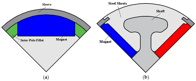
Figure 20. High-speed PM machines with SPM and spoke-type IPM rotor structures. (a) SPM. (b) Spoke-type IPM.
In the literature, several methods have been proposed to improve the mechanical strength for high-speed applications of IPM rotor structures. In [23], a retaining shield rotor construction is proposed to improve the mechanical strength of high-speed IPM rotors. This novel rotor structure is a combination of silicon-steel sheet and stainless-steel plate, Figure 21. The former with a small flux iron bridge can reduce the flux leakage, and the latter with large tensile yield strength can withstand the centrifugal forces. The research focuses on the influence of the axial proportions of stainless-steel plates on the mechanical stress and electromagnetic performance, especially on the torque and rotor losses, and a trade-off should be satisfied. Ref. [22] employs solid semi-magnetic stainless steel to improve the mechanical strength of the high-speed IPM rotor rather than the combination of silicon-steel and stainless-steel. The limitation of solid rotor design is the large rotor eddy current loss. This has led to the proposal of axially segmented and circumferentially slitted solid rotors for reducing the losses. These are optimized and compared in [22]. The results show that, with the same conditions, the circumferentially slitted rotor structure has significantly smaller eddy current loss than the axially segmented solid rotor. In addition, for a 36-slot/2-pole high-speed IPM machine, [112] employs 6 iron ribs between magnets to reduce the rotor maximum stress and protect the rotor core and magnets, Figure 22. Meanwhile, radial, Halbach, and parallel magnetized rotors are compared in [112], and the results show that the Halbach magnet array can not only produce the sinusoidal air-gap flux density waveform but also reduce the torque ripple and roughly maintain the output torque.
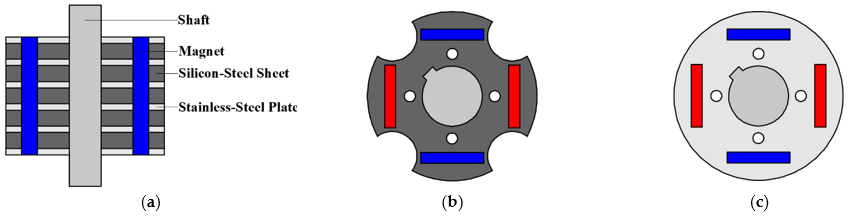
Figure 21. A retaining shield rotor construction for high-speed IPM machines [23]. (a) Retaining shield rotor construction. (b) Silicon-steel sheet. (c) Stainless-steel plate.
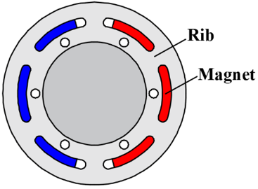
Figure 22. 2-pole rotor structure with 6 iron ribs between magnets [112].
4.2. SPM
As mentioned before, the SPM rotor with retaining sleeves has better mechanical strength and higher critical speed than IPM. In general, the SPM rotor design for high-speed applications mainly focuses on the trade-offs between electromagnetic performance and mechanical, thermal, and dynamic constrains.
4.2.1. Sleeve Design
For high-speed applications, the sleeve is the most important part and has a close relationship with machine performance. Firstly, although the increased sleeve thickness improves mechanical strength, the increased effective air-gap length due to the sleeve being nonmagnetic leads to a decrease in air-gap flux density and output torque. Secondly, sleeves made from non-conducting material with high mechanical strength have higher critical speed. However, their low thermal conductivity may lead to high maximum temperature concentration in the rotor and thus increase the demagnetization risk. Therefore, the sleeve thickness and sleeve material are widely researched in the rotor design for HSPM machines.
Ref. [113] describes a high tensile retaining sleeve material, Kevlar, it can increase the critical speed of rotor. [114] compares 36-slot/2-pole HSPM machines with different sleeve materials for a 117 kW 60 krpm micro gas turbine application, such as stainless steel, carbon fibre, copper iron alloy, and copper. The comparison focuses on the electromagnetic performance and temperature distribution. The results show that the copper iron alloy sleeve increases the flux leakage, and three non-magnetic sleeves have the same flux linkage. More importantly, although the rotor with a carbon fibre sleeve has the smallest rotor losses, the rotor with a copper sleeve has the lowest maximum temperature due to high thermal conductivity and relatively small eddy current losses. In [25], carbon fibre and glass fibre sleeves for SPM high-speed machines are compared. It is shown that the glass fibre sleeve cannot withstand the centrifugal force when the rotor surface speed is larger than 150 m/s, so that the carbon fibre sleeve can allow higher critical speeds. With different materials of magnets and sleeves, the rotor mechanical stress is computed by an analytical model and verified by the FE model in [115]. The results show that the combination of Titanium sleeve and NdFeB magnet has high mechanical strength.
Apart from the sleeve material, the sleeve shape can also be designed to reduce the rotor eddy current loss. [116] proposes a new grooved sleeve design to reduce the rotor eddy current loss, Figure 23. Circumferential, axial, and mixed grooves are compared, and the results show that the Titanium sleeve with circumferential grooving has the lowest eddy current losses and the smallest maximum stress in the sleeve. In [117], a new sleeve design is employed to reduce the sleeve eddy current loss by slitting the sleeve to split the eddy current loops, Figure 24. However, the mechanical stress withstand is significantly reduced and should be checked carefully.
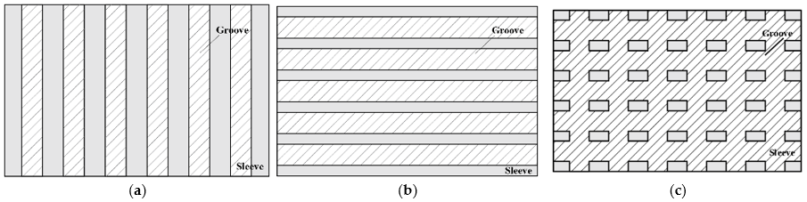
Figure 23. Sleeve design with axial and circumferential grooves [116]. (a) Axially grooved sleeve. (b) Circumferentially grooved sleeve. (c) Mixed grooved sleeve.
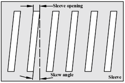
Figure 24. A new sleeve design for reducing eddy current loss [117].
In [15], a copper shield between the retaining sleeve and magnets is employed to potentially reduce the total rotor eddy currents by utilising the shielding effect. The results show that as the shield thickness is increased, the total rotor loss decreases due to the stronger shielding effect. In addition, according to the thermal analysis, with a copper shield, the maximum rotor temperature is reduced from 240 °C to 70 °C. However, the air-gap flux density is reduced due to the increased effective air-gap. In [118], the sleeve eddy current loss decreases with the increases of the copper shield thickness firstly and then remains almost the same since the thickness is beyond the skin depth of the copper shield. In addition, with and without a copper shield, the effect of sleeve axial segmentation on sleeve losses is investigated. The results show that a sleeve without segmentation and with a copper shield is the most effective solution to reduce sleeve losses. Ref. [119] employs a radial multilayer sleeve to reduce the rotor eddy current loss, which decreases the rotor losses and PM temperature under the same output performance and mechanical strength. Researchers in [120] propose a hybrid protective measure consists of Titanium alloy and carbon fibre. The Titanium alloy shield can not only improve the mechanical strength but also reduce the losses of the carbon fibre sleeve and magnets. Although large losses exist in the Titanium alloy shield, the maximum temperature of the sleeve with Titanium alloy is almost the same as that of the sleeve without Titanium alloy due to the high thermal conductivity of the Titanium alloy shield.
4.2.2. Pole Arc to Pole Pitch
Ref. [46] investigates the influence of the ratio of pole arc to pole pitch, i.e., pole arc coefficient (αp), on electromagnetic performance. With the increase of pole arc coefficient, the PM loss, cogging torque, and no-load current increase due to the increased amplitude of the fundamental back-EMF and harmonic components, which is verified by [32,121]. The increased EMF leads to a decreased stator active length. Therefore, a trade-off should be satisfied based on the requirements.
When the pole arc coefficient is less than ‘1’, an inter-pole air-gap exists, Figure 25a, which may lead to large local stress in the sleeve due to the uneven distribution of magnets [33]. Therefore, [120] compares different materials of inter-pole filler to reduce the sleeve stress and improve the rotor stiffness, Figure 25b, such as plastics, carbon fibre, and Titanium alloy. In [33], the materials of inter-pole filler are PMs, i.e., αp = 1, air, glass fibre, and iron. The results show that the Titanium alloy and iron inter-pole fillers have the lowest sleeve stress. However, the Titanium alloy and iron inter-pole fillers will lead to the increased rotor eddy current loss due to high electrical conductivity. Therefore, [120,46] employ non-magnetic non-conductive plastics as inter-pole fillers and [25,33,114,122] adopt SPM without pole gap, i.e., αp = 1, for their different design requirements. In addition, the iron inter-pole filler, is employed by [84,123]. Ref. [122] analyses the rotor stress for a HSPM machine with segmented magnets retained by a carbon fibre sleeve, without a pole gap. It shows that magnet edging effect caused by segmentation leads to sleeve stress concentration but reduces the magnet tangential stress; thus, the number of PM segments should be optimized to avoid stress concentration.
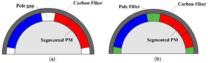
Figure 25. Two SPM rotor structures with different pole gap materials. (a) Magnets with air pole gap. (b) Segmented magnets with pole filler.
4.3. Solid PM
There are two solid PM rotor structures: a solid PM with a sleeve and solid PM with a hollow shaft. The design considerations mainly focus on the mechanical stress due to ultra-high-speed operation.
4.3.1. Solid PM with Sleeve
The solid PM with sleeve is commonly used due to its simple rotor structure and easy assembly process, Figure 19c, especially for small size rotor [26,28,36,124]. In [27], the 2-pole solid PM is used and magnetized as a whole, leading to the symmetry of mechanical strength and electromagnetic performance. In addition, the solid PM is segmented axially to reduce the rotor eddy current loss and to simplify the assembly process of the magnets, the high rotor mechanical strength and electromagnetic performance are unimpaired by the segmentation [36]. Ref. [124] compares different materials of magnets and sleeves for a 500 W 400 krpm 2-pole slotless HSPM machine with a solid PM rotor. The magnet materials are NdFeB and Sm2Co17, and the sleeve materials include Titanium alloy, SUS304, Inconel718, and carbon fibre. The results show that the combination of Inconel718 sleeve and NdFeB (N42SH) magnet has high mechanical strength and the largest rotor dynamic safety factor and is the best. The SUS304 sleeve is the worst since it cannot meet the mechanical stress requirement.
4.3.2. Solid PM with Hollow Shaft
In [29], a 2 kW 200 krpm slotless HSPM machine is designed for a centrifugal compressor drive application. This design employs a solid PM rotor structure, and the magnets are located inside a hollow shaft (Titanium), Figure 26a. This rotor structure can improve the rotor stiffness and significantly increase the first critical speed. [86] modifies the equation of natural frequency calculation considering the solid PM with hollow shaft, and the analytical prediction shows that the first natural frequency is well above the rated frequency. Ref. [125] proposes a novel solid PM rotor design with a hollow shaft, which consists of an amorphous rotor core, solid PM, and a hollow shaft, Figure 26b. It should be noticed that epoxy is employed in the gaps between PMs and rotor core to improve the rotor mechanical strength. The advantage of the novel rotor structure is that since the PM is inserted into the rotor core, the manufacture and assembly are simple. However, this rotor structure will lead to a large shaft loss, which may increase the rotor temperature and the demagnetization risk.
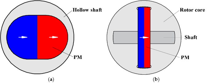
Figure 26. Solid PM with hollow shaft rotor structure. (a) Conventional hollow shaft [29]. (b) Novel hollow shaft [125].
4.4. Summary
In this section, the applications, advantages, and disadvantages of IPM, SPM, and solid PM rotor structures are summarised in Table 4. The selection of rotor structure depends on the constraints of mechanical stress and machine size. In general, the solid PM rotor structure has the highest mechanical strength, but the equivalent airgap is the largest. The IPM rotor structure has the lowest mechanical strength, but the cost is the lowest. The SPM with sleeve rotor structure has a better trade-off between electromagnetic performance and mechanical stress, it is widely employed in HSPM machines.
In summary, the main types and subtypes of high-speed PM machines have been highlighted in Figure 27, and their applications, advantages, and disadvantages have been summarized in Tables 1–4.
Table 4. Applications, advantages, and disadvantages of different rotor structures.
|
|
IPM |
SPM |
Solid PM |
|
Application |
|
|
|
|
Advantages |
|
|
|
|
Disadvantages |
|
|
|
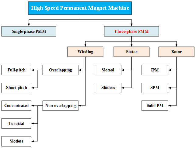
Figure 27. Main types and subtypes of high-speed PM machines.
5. Parasitic Effect
The high-speed operation results in an increased number of parasitic effects which do not exist or are not important in the low-speed and moderate-speed operation, such as stator iron loss, AC copper loss, rotor eddy current loss, windage loss, rotor dynamic characteristic, rotor vibration, and thermal aspects.
5.1. Stator Iron Loss
Compared with low-speed and moderate-speed conventional machines, the stator iron loss becomes the dominant loss in high-speed machines due to the high frequency. Therefore, the calculation of stator iron loss should be included in the analysis and design of high-speed machines. In general, the Bertotti model [126] is employed in the analytical computation of stator iron loss. There are three losses included in the classic Bertotti model, namely, hysteresis loss (Ph), eddy current loss (Pe), and anomalous loss (Pa), as shown by

where kh, ke, and ka are the hysteresis, eddy current, and additional loss coefficients, respectively. These coefficients depend on the material and are invariant with the frequency (f) and the flux density magnitude (Bm). However, for high-speed operation, since the magnetic flux waveform in the iron core is not exactly sinusoidal, the eddy current loss coefficient is a variable with frequency.
Ref. [127] develops a method to predict the iron loss in a PM BLDC machine under on-load condition. It indicates that the on-load iron losses is markedly higher than open-circuit iron losses. In addition, [128] calculates the rotational stator iron loss caused by the angle of lag between magnetic field strength (H) and flux density (B), i.e., non-circular flux density loci. In [129], the magnetic flux variation at each point of the iron core is obtained, and, the radial and tangential components of the flux density fundamental and harmonics are found by Fourier analysis. Moreover, the additional iron loss due to rotational magnetic flux in the iron core is considered. The results show that for high-speed machines, the stator iron loss is affected not only by the alternating flux effect but also by the rotational flux effect. In [100], the skin effect is considered when the frequency is above 2 kHz, and the accuracy of analytically predicted results is improved. In [39], the additional losses due to magnetic anomalies, manufacturing processes, and rotational fields are considered.
5.2. AC Copper Loss
The copper losses in HSPM machines include two basic components, DC and AC copper losses. The DC copper loss component has a close relationship with output torque, and its thermal dependence is well understood. The AC copper loss is caused by the skin effect and proximity effect and should be analyzed because of the high frequency current, pulse width modulation (PWM), and large slot leakage flux in HSPM machines [130,131].
Skin effect is a tendency for alternating current to flow mostly near the outer surface of the conductor. The effect becomes more and more apparent with the increase of frequency, and thus it should be considered in high-speed PM machines. Proximity effect is a tendency for alternating current to flow in a smaller region due to the magnetic field caused by nearby conductors. In general, the skin effect can be eliminated when the conductor diameter is smaller than the skin depth under the rated frequency. [132] divides each winding turn into several parallel wires to reduce the diameter of each conductor and avoid skin effect. The proximity effect can be reduced by using Litz wire [133], which is constructed using hundreds of small-diameter strands divided into many bundles. The strands in each bundle are twisted. [50] measures the no-load power losses of the slotless HSPM machines with and without Litz wires. The results show that under the rated speed (75 krpm), the power loss with Litz wires is lower than 100 W, but the power loss without Litz wires is higher than 400 W. However, Litz wire also has drawbacks, such as the high cost and inferior thermal performance.
In addition, the proximity effect can also be affected by the disposition of the conductors. It is found that the proximity effect can be significantly reduced when the conductors are located at the bottom of slots since the additional losses are concentrated at the conductors at the top of the slot due to the influence of the magnetic field caused by the PM [131,134]. However, it is worth noting that for high-speed slotless machines, the magnetic field generated by the PM is much larger than the field caused by the nearby conductors, and therefore the proximity effect can be neglected [28].
5.3. Rotor Eddy Current Loss
In high-speed machines, although the rotor eddy current loss is relatively small, the poor cooling capability may result in overheating in the rotor and demagnetization of magnets. Therefore, the rotor eddy current loss should be considered and reduced. In general, two factors lead to the rotor eddy current losses, the first is the space harmonics due to the armature MMF and slot openings, and the second is the time harmonics of armature current caused by the PWM. However, in HSPM machines, the large air-gap reduces the effect of space harmonics, and the time harmonics play the dominant role in generating the rotor losses [15,135].
As mentioned before, compared with 6-slot/2-pole HSPM machines, the 3-slot/2-pole HSPM machine has the largest rotor eddy current loss due to the space harmonics from the armature MMF, this loss significantly increases as the speed increases. In [110], the 2-pole slotless HSPM machines with toroidal, helical, and concentrated windings and square-/sine-waves generated by PWM inverters are compared in terms of the rotor eddy current loss. The results show that machines fed by square-wave PWM voltages have higher rotor eddy current losses compared to the ones fed by sine-wave PWM voltage due to the larger time harmonics of armature current. In addition, slotless machines with concentrated windings have the largest rotor losses due to the space harmonics from the armature current.
In [136], the 24-slot/4-pole HSPM machines with Halbach and parallel magnetized rotors are compared in terms of rotor losses. According to the time and space harmonic analysis, the machine with a Halbach magnetized rotor has smaller rotor losses than the machine with a parallel magnetized rotor. However, the segmentation of the Halbach magnetized rotor is not mentioned, which may have a significant effect on the reduction of rotor losses. Ref. [137] discusses the influence of magnet thickness on the rotor eddy current loss of the 3-slot/2-pole HSPM machines with a constant output torque. Since the phase current and armature reaction decrease with the increase of magnet thickness, the rotor eddy current loss decreases. Ref. [72] adopts the auxiliary slots in the 3-slot/2-pole PM machines to reduce the rotor eddy current loss by partially cancelling the asynchronous harmonics produced by the armature field and slot, which has been mentioned in section III. A. In addition, [24] increases the stator teeth width to reduce the rotor eddy current loss.
Except for reducing the influence of space and time harmonics, splitting the eddy current loops in the rotor is a direct solution to reduce the magnet eddy current loss. Although [138] believes that segmenting the magnets is better for low speeds and [65,116] consider that PM segmentation will complicate the manufacturing process and is difficult for small size rotors, several large size HSPM machines still employ the rotor magnet segmentation to reduce the magnet eddy current loss [3,139]. In [120], the magnet is divided into three segments per pole in the circumferential direction. Axial segmentation of magnets is adopted in [30].
5.4. Windage Loss
The windage loss results from the aerodynamic loss when the rotor rotates, and it becomes significant as the speed increases. In general, the rotor is modelled as a cylinder to find the windage loss [140], the result is given by equation 3

where ρair is the air gap density, ω is the angular speed, Rr and la are the rotor radius and length, respectively. Cf is the friction coefficient and is determined by the air gap structure and rotor surface condition. Compared with the analytical method, fluid field analysis is a more accurate method to calculate the windage loss since the friction coefficient is difficult to determine for the theoretical analysis.
Ref. [37] studies the windage loss of a 24-slot/2-pole HSPM machine with a rated speed of 60 krpm by the 3D FEM of the fluid field and an experimental study. It shows that the windage loss is a large part of the total losses and is larger than the core loss at the rated speed. Refs. [129,139] show that the windage losses increase with the increase of rotor speed, rotor roughness height, and ventilation speed (axial cooling air velocity). Therefore, it is advantageous to use a sleeve material with a smooth surface and employ a suitable ventilation speed to balance windage losses and cooling conditions.
5.5. Rotor Dynamic and Vibration
During high-speed operation, the rotor has a great amount of rotational energy and a small amount of vibration energy. The purpose of rotor dynamics is to make sure the vibration energy is as small as possible. For high-speed machines, it is very important to accurately predict the natural frequency of the rotor to avoid the rated operation frequency close to the natural frequency.
In [141], FE analysis is used to establish the dynamic model of the rotor and compute its natural frequency. The results show that the shaft extension has a significant influence on the natural frequency, and in order to move rotor bending modes beyond the operating speed range, the shaft should be short and have a large diameter, i.e., small L/D ratio [44]. However, in [28], the length of the shaft is adjusted such that the rated speed (500 krpm, 8.333 kHz) falls between the second and the third bending modes. Ref. [142] investigates the influence of rotor static eccentricity on the rotor vibration by unbalanced magnetic force and eccentric mass force. The results show that the eccentric mass force leads to fundamental frequency vibration, which is the main source of rotor vibration. In addition, the static/dynamic rotor eccentricities have significant influence on back-EMF, cogging torque, and UMF [73,143,144,145], which has been mentioned in Section 3.
5.6. Thermal Aspect
In high-speed machines with high power density and small size, thermal analysis is necessary due to large machine loss and low cooling capability of the rotor. The computational fluid dynamics (CFD) method is adopted to calculate the temperature rise distribution, in which the coolant flow rate, the velocity, and the surface heat transfer coefficient should be determined simultaneously.
Ref. [32] optimizes the stator structure by the CFD method, and the results show that most axial coolant flows through the inner and outer slots whilst little enters the air gap. The highest winding temperature is found near the outlet, which is approximately 96.0 °C. The hottest spot occurs in the middle of the rotor, which is 125.5 °C. Since the complex modelling and meshing procedure requires certain skills and is quite time-consuming, a time-saving lumped-parameter thermal network (LPTN) linked with the CFD modelling is employed in [35]. In this hybrid method, the fluid and temperature fields are firstly evaluated by the CFD modelling, and then the LPTN model is created.
However, in practice, both electromagnetic and thermal solutions should be done simultaneously, accounting for the inter dependence among the thermal and electromagnetic fields, mechanical and aerodynamic aspects, as well as the cooling techniques, particularly the temperature effect on the PM characteristics, the stator copper and iron losses, and the rotor PM eddy current loss etc. There remain much to be further investigated.
This entry is adapted from the peer-reviewed paper 10.3390/wevj13010018
References
- Shen, J.X.; Qin, X.; Wang, Y. High-speed permanent magnet electrical machines—Applications, key issues and challenges. CES Trans. Electr. Mach. Syst. 2018, 2, 23–33.
- Gerada, D.; Mebarki, A.; Brown, N.; Gerada, C.; Cavagnino, A.; Boglietti, A. High-speed electrical machines: Technologies, trends, and developments. IEEE Trans. Ind. Electron. 2014, 61, 2946–2959.
- Van Millingen, R.D.; Van Millingen, J.D. Phase shift torquemeters for gas turbine development and monitoring. In Proceedings of the International Gas Turbine and Aeroengine Congress and Exposition, Orlando, FL, USA, 3–6 June 1991; p. 91-GT-189.
- Li, S.; Li, Y.; Choi, W.; Sarlioglu, B. High-speed electric machines: Challenges and design considerations. IEEE Trans. Transp. Electrification. 2016, 2, 2–13.
- Arkkio, A.; Jokinen, T.; Lantto, E. Induction and permanent magnet machines for high speed application. In Proceedings of the International Conference on Electrical Machines and Systems (ICEMS), Nanjing, China, 27–29 September 2005; pp. 871–876.
- Miller, T.J.E. Single-phase permanent-magnet machine analysis. IEEE Trans. Ind. Applicat. 1985, IA-21, 651–658.
- Kurihara, K.; Rahman, M.A. High-efficiency line-start interior permanent-magnet synchronous machines. IEEE Trans. Ind. Applicat. 2004, 40, 789–796.
- Mayer, J.S.; Wasynczuk, O. Analysis and modeling of a single-phase brushless DC machine drive system. IEEE Trans. Energy Convers. 1989, 4, 473–479.
- Huang, D.R.; Fan, C.Y.; Wang, S.J.; Pan, H.P.; Ying, T.F.; Chao, C.M.; Lean, E.G. A new type single-phase spindle machine for HDD and DVD. IEEE Trans. Magn. 1999, 35, 839–844.
- Bentouati, S.; Zhu, Z.Q.; Howe, D. Permanent magnet brushless DC machines for consumer products. In Proceedings of the International Conference on Electrical Machines and Drives, Canterbury, UK, 1–3 September 1999; pp. 118–122.
- Bentouati, S.; Zhu, Z.Q.; Howe, D. Influence of design parameters on the starting torque of a single-phase PM brushless DC machine. IEEE Trans. Magn. 2000, 36, 3533–3536.
- Zhou, F.Z.; Shen, J.X.; Fei, W.; Lin, R. Study of retaining sleeve and conductive shield and their influence on rotor loss in high-speed PM BLDC machines. IEEE Trans. Magn. 2006, 42, 3398–3400.
- Jang, K.; Won, S.; Kim, T.; Lee, J. Starting and high-speed driving of single-phase flux-reversal machine for vacuum cleaner. IEEE Trans. Magn. 2005, 41, 3967–3969.
- Chen, Y.; Chen, S.; Zhu, Z.Q.; Howe, D.; Ye, Y.Y. Starting torque of single-phase flux-switching permanent magnet machines. IEEE Trans. Magn. 2006, 42, 3416–3418.
- Ertan, H.B.; Dag, B.; Capolino, G. Calculation of parameters of single-phase PM machine for design optimization. IEEE Trans. Energy Convers. 2005, 20, 538–548.
- Chen, Y.; Celik, T.; Greetham, S. Control of a Brushless Machine. U.S. Patent Application 20110254483A1, 13 April 2011.
- Tüysüz, A.; Zwyssig, C.; Kolar, J.W. A novel machine topology for high-speed micro-machining applications. IEEE Trans. Ind. Electron. 2014, 61, 2960–2968.
- Zhu, Z.Q.; Ng, K.; Howe, D. Design and analysis of high-speed brushless permanent magnet machines. In Proceedings of the International Conference on Electrical Machines and Drives, Cambridge, UK, 1–3 September 1997; pp. 381–385.
- Arumugam, P.; Xu, Z.; La Rocca, A.; Vakil, G.; Dickinson, M.; Amankwah, E.; Hamiti, T.; Bozhko, S.; Gerada, C.; Pickering, S.J. High-speed solid rotor permanent magnet machines: Concept and design. IEEE Trans. Transp. Electrif. 2016, 2, 391–400.
- Zhang, J.; Chen, W.; Huang, X.; Fang, Y.; Zhang, J.; Ma, J.; Cao, W. Evaluation of applying retaining shield rotor for high-speed interior permanent magnet machines. IEEE Trans. Magn. 2015, 51, 1–4.
- Bianchi, N.; Bolognani, S.; Luise, F. Potentials and limits of high-speed PM machines. IEEE Trans. Ind. Appl. 2004, 40, 1570–1578.
- Shigematsu, K.; Oyama, J.; Higuchi, T.; Abe, T.; Ueno, Y. The study of eddy current in rotor and circuit coupling analysis for small size and ultra-high-speed machine. In Proceedings of the International Power Electronics and Motion Control Conference (IPEMC), Xi’an, China, 14–16 August 2004; pp. 275–279.
- Binder, A.; Schneider, T.; Klohr, M. Fixation of buried and surface-mounted magnets in high-speed permanent-magnet synchronous machines. IEEE Trans. Ind. Appl. 2006, 42, 1031–1037.
- Hesmondhalgh, D.E.; Tipping, D.; Amrani, M. Design and construction of a high-speed high performance direct-drive handpiece. IEE Proc. B Elec. Power Appl. 1987, 134, 286–296.
- Wang, F.; Zong, M.; Zheng, W.; Guan, E. Design features of high speed PM machines. In Proceedings of the International Conference on Electrical Machines and Systems (ICEMS), Beijing, China, 9–11 November 2003; Volume 1, pp. 66–70.
- Zwyssig, C.; Kolar, J.W.; Thaler, W.; Vohrer, M. Design of a 100 W, 500,000 rpm permanent-magnet generator for mesoscale gas turbines. In Proceedings of the IEEE Industry Applications Society Annual Meeting, Hong Kong, China, 2–6 October 2005; pp. 253–260.
- Zheng, L.; Wu, T.X.; Acharya, D.; Sundaram, K.B.; Vaidya, J.; Zhao, L.; Zhou, L.; Ham, C.H.; Arakere, N.; Kapat, J.; et al. Design of a super high speed cryogenic permanent magnet machine. IEEE Trans. Magn. 2005, 41, 3823–3825.