Your browser does not fully support modern features. Please upgrade for a smoother experience.
Please note this is an old version of this entry, which may differ significantly from the current revision.
Subjects:
Engineering, Electrical & Electronic
One of the main challenges of today’s electrical power engineering is the symmetrization of grid voltages and the minimization of reactive power flows in distribution networks. There are many negative effects associated with asymmetry in power systems, such as increased losses in electric motors, harmonics transferred to DC systems, or phase currents inequality.
- microgrid
- reactive power compensation
1. Introduction
One of the main challenges of today’s electrical power engineering is the symmetrization of grid voltages and minimization of reactive power flows in distribution networks. There are many negative effects associated with asymmetry in power systems, such as increased losses in electric motors, harmonics transferred to DC systems, or phase currents inequality [1]. The research on four-wire converters and voltage asymmetry compensation methods in the distribution networks has already been carried out. The solution presented in [2] describes the control method for inverters, which is characterized by resistive behavior for grid disturbances. Voltage distortions are also inextricably linked with the load unbalances. There are proposals of load compensation under distorted voltages that are based on instantaneous symmetrical component theory with positive sequence extraction [3] or differentially rotating reference frame systems [4]. Other approaches are connected with neutral current compensation [5,6] and fuzzy neural networks [7]. However, the problem that has not been addressed in the research publications is the correlation between the asymmetry of phase angles and the reactive power compensators output power factor. It should be emphasized that non-linear and asymmetric loading of distribution networks [8,9] causes significant voltage asymmetry but also the phase angle shift. This problem is exacerbated in the systems where the short-circuit impedance is high—we can definitely include microgrids among them [10,11]. For the aforementioned reason, it is required to develop methods of controlling active and reactive power in the microgrid asymmetry states, which will be immune to the angular asymmetry between voltage vectors.
The low voltage distribution system is characterized by the fact that a large number of receivers with various characteristics are connected to it [12]. Most of the devices connected to the grid are single-phase loads. An increasing number of them have power systems which are based on electronic converters [13]. The use of this technology results from the requirements regarding their dimensions, weight, and price. The major problem arising from the use of such converters is the fact that they consume current in a non-linear manner [14]. An additional problem is the reactive power demand. Due to the presented factors, the parameters of the power grid deteriorate [15,16]. Phase-to-phase asymmetry appears, the voltage total harmonic distortion (THD) in the grid increases, and the increasing amount of reactive power reduces the grid capacity and causes voltage drops. The parameter that also changes is the phase angle between the voltage vectors. The measurements in the low voltage networks with a large number of consumers show that the phase angles are not symmetrical. Figure 1 and Figure 2 show the measurements made using Kyoritsu KEW6310 (Kyoritsu, Tokyo, Japan), which is power quality analyzer.
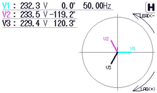
Figure 1. The angular asymmetry between voltage vectors: reference grid measurement.
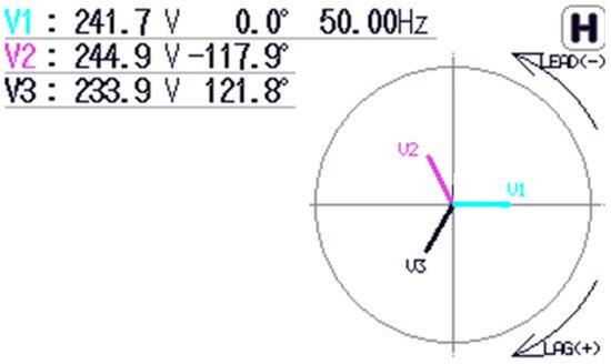
Figure 2. The angular asymmetry between voltage vectors: microgrid measurement.
Subsequent measurements were made in the microgrid, where one of the phases was heavily loaded. The angular error has been observed to become worse. The voltage asymmetry between phase 2 and phase 3 is 11 V. The results are presented Figure 2.
The angular asymmetry between voltage vectors has a significant impact on the operation of three-phase systems containing transformers, motors, and power converters. This article discusses the problem of reactive power compensation in a microgrid by a three-phase converter in the presence of angular errors. The microgrid system was selected as the research object due to high impact of its parameter fluctuations on the stability and efficiency of the entire system. A four-wire three-level AC/DC converter was used to solve the presented problem. This solution can be implemented particularly in radial grids and non-urban areas as a device maintaining the parameters of the electrical grid.
2. Phase-Independent Reactive Power Compensation with the Use of Four-Wire Hybrid Converter with Proportional-Resonant Regulators
The microgrids are characterized by the fact that their structure includes devices which are working as the current sources. These are generators based on internal combustion engines, electrochemical or mechanical energy storages, and renewable energy sources. All these devices are connected with each other by converters that synchronize with the grid. A typical structure of such a system is shown in Figure 3.
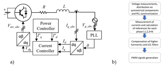
Figure 3. (a) Typical control structure of a converter integrated with renewable energy sources. (b) The flowchart of the multi-resonant algorithm. I*q, I*d—Reference current value in dq frame; Id, Iq—feedback currents after Park transform; Vdq—voltage signals in dq frame; Ig_abc, Vg_abc—Three phase instantaneous currents and voltages. Vinv_abc—three phase reference signals for PWM module.
The three-phase converter system for renewable energy sources presented in Figure 3 uses PLL (Phase-locked Loop) systems for synchronization with the grid [17,18,19]. These systems can be divided into those with a system of decomposition into symmetrical components and without this functionality. A common feature of these systems is the generation of a sawtooth signal common to three phases, which maps the actual vector angle of the grid voltage. Unfortunately, the PLL systems used in microgrid-connected three-phase converters do not meet the proper synchronization requirements connected with the angular asymmetry between the individual phases. When this asymmetry is not detected, the unwanted amounts of power will be drawn or delivered by the converters connected to the microgrid system. It should be emphasized that the microgrids are loaded asymmetrically. As a result, the value of active and reactive power is different in each of the phases. Therefore, the developed reactive power compensator should provide phase-independent reactive power compensation in the presence of angular asymmetry between voltage vectors. This type of operation can be achieved by replacing the classical synchronization and power calculation system based on the classical theory of instantaneous power with a solution that takes into account the phase angles of individual phases. The system is complemented by the use of a converter system that enables independent power control for each of the phases, despite the presence of disturbances in the microgrid parameters. The flowchart of the multi-resonant algorithm is presented in Figure 3a.
The proposed solution is a four-wire AC/DC converter (Figure 4). Its construction is based on a three-level T-type topology [20,21,22]. The fourth branch acts as a neutral wire and it enables phase-independent reactive power compensation. This solution is realized by a serial connection of Cx1 and Cx2 capacitors. As a result, the DC bus voltage is split in two. The application of increased capacity on the DC bus improves the operation of the system in dynamic states. In this context, the use of supercapacitors may be considered [23,24]. LN inductance is connected between neutral point and Q13–Q14 transistors. This connection allows for the active voltage stabilization on split DC bus. The inductive-capacitive-inductive (LCL) filter is used at the output of the converter, tuned to eliminate interference from the switching transistors.
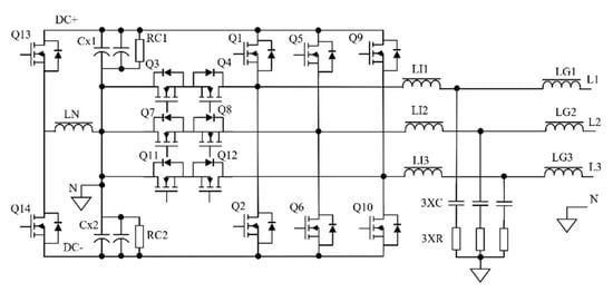
Figure 4. Hybrid converter in a three-phase, three-level four-wire configuration to enable the phase-independent reactive power compensation.
Due to the fact that each phase of the converter is controlled independently, the control system was considered as single-phase for further analysis. Subsequently, the system was expanded to three phases during simulation studies.
The main problem which is not mentioned by literature is the proper synchronization with unbalanced phase angles and correct calculation of the converter output currents value. The basic method uses a three-phase synchronous reference frame phase-locked loop (SRF-PLL) [25,26]. The synchronization method generates a sawtooth signal θ, which carries a phase angle value in the range from 0 to 2π.
The synchronization angle θ is used for the calculation of active and reactive current values in the dq frame. This calculation is realized in two steps: The first one is to pass the current signal through the Second-Order Generalized Integrator filter (SOGI), which shifts the measured phase by 90 degrees [27,28]. The second one is the active and reactive current components generation via the Park transform, which is based on the previously calculated signal by the PLL and phase current signal.
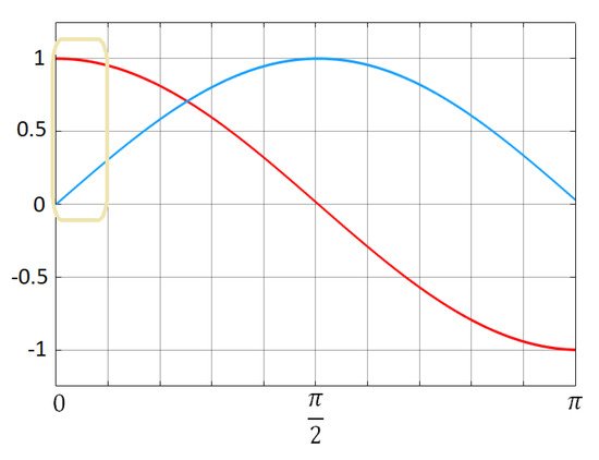
The method presented in Figure 5a is simple and efficient but causes current calculation errors if the voltage vectors of the weak utility grid are no longer shifted by 120 degrees. Figure 6 presents the value of dq signals as a function of the synchronization angle. The solution that will overcome these errors is presented in Figure 5b. Instead of a calculation of three 120 degree-shifted signals by a single PLL, three separate PLLs are used to calculate the correct angle of the voltage in each phase independently. In this case, the problem presented in Figure 6 no longer exists: the calculated currents are the base of the active and reactive current control loop.
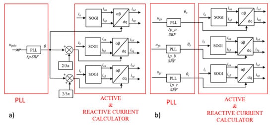
Figure 5. The method of active and reactive power calculation. (a) System with standard three phase-based PLL signal. (b) System with three individual PLL signals, which is the proposed method for the presence of angular asymmetry between voltage vectors.
This entry is adapted from the peer-reviewed paper 10.3390/en15020497
This entry is offline, you can click here to edit this entry!