Buckling of structural elements is a phenomenon that has great consequences on the bearing capacity of structures. Historically, there have been serious buckling-related structural accidents that have resulted in loss of human lives and high material costs.
1. Introduction
Throughout history, numerous accidents and collapses of structures have occurred due to buckling of steel structural elements, which resulted in loss of human lives and high material costs. Several bridge accidents, such as Dee Bridge, 1847, Tay Bridge, 1879, Quebec Bridge, 1907, and Tacoma Bridge, 1940, stimulated a considerable amount of research into the buckling behavior of steel members
[1]. Augenti and Parisi
[2] discussed the collapse of a long-span steel roof structure which fell down suddenly during construction as a result of an out-of-plane buckling phenomenon induced by wind. Al-Marwaee
[3] stated that the World Trade Centre towers were designed with steel columns braced against buckling by the floors. The high temperatures in the fires weakened the steel brace systems and columns, causing the buckling length of columns to increase and, consequently, the onset of buckling.
2. Development of Steel Construction
With the advent of iron as a new structural material for construction both in civil engineering and in building construction in the middle of the 19th century in Europe, a new series of structural typologies where metallic members acquire particular relevance appear as a result.
These new metallic members that initially were made of cast iron were much thinner compared to previous members, basically made of stone as were the case of the pillars and columns made of marble, brick, wood, or masonry using some other material.
The slenderness of the new cast iron elements carried with them the idea of buckling for loads that were less than that they could support in simple compressive stress of the material of which they were made: cast iron in the first place, and later, steel.
In previous buildings where the slenderness of walls, pillars, and columns rarely surpassed a geometric ratio of 1:10, i.e., a geometrical slenderness less than 10—which would equate a mechanical slenderness in the order of 35 for a rectangular section whose total width was at its greatest 10 times its thickness—the problem of compressive buckling of any of the members was seldom seen as a real problem. Should any designer any time dare to surpass the recommended slenderness, the trial methods would tell him where the limits were to be contemplated in his designs.
One of the first bibliographic references to more complex equations or formulae that took buckling in cast iron columns into consideration in Spain came thanks to José Marvá y Mayer, Engineer General
[4], who, around the year 1910, makes some reference, mainly taken from North American, British, and French research, to formulae for the dimensions of cast iron columns.
In his reference work
[4], José Marvá provides a number of formulae to be applied to find out the dimensions of solid or hollow circular cast iron columns using expressions in line with the following equation. He calls it Hodgkinson’s formula:
where
Po Fracture/buckling load, in kp.
d Outer diameter of the column, in cm.
L Length of the column, in dm.
K Coefficient of values 10,320 for a fixed bar, 5954 for fixed–pinned, and 2977 for pinned–pinned.
The numerical coefficient “K” of the equation is dimensional. Marvá recommended a working design on the order of six times less than that of fracture. This formula worked for those columns whose length contained 25 and 60 times their diameter, precisely in the part of the column in which buckling was clearly appreciated, the reason being that the corresponding mechanical slenderness to such values would be located between 90 and 200, approximately.
Eaton Hodgkinson (1789–1861)
[5] was a British self-taught engineer who brought forward a number of experimental formulae he obtained from his own tests. The formulae, widely used all through the 19th century, dealt with compressive buckling of such members as metallic columns.
In his work
[4], Marvá refers to formulae proposed by the French researchers M. Barré and G.H. Lowe (1859) to apply to problems related to establishing the dimensions of wooden and steel columns.
G.H. Lowe proposes the following expression—the original wording of which remains to this day—for solid cast iron columns:
where
P0 Maximum fracture load which the column can withstand.
α Coefficient that depends on the boundary conditions, 1 for a fixed member, 4/7 for a fixed–pinned member, and 2/7 for a pinned–pinned member.
R′ Simple compressive fracture stress of the material the column is made of.
w Cross-sectional area.
L Member length.
d Outer diameter of the column.
The geometrical slenderness squared in Equation (7) appears in the denominator of the previous expression to act as a corrector to the buckling stress.
Should the expression be termed in today’s terms, it would be as follows:
Later, in the same work, for more general cases, Marvá
[6] proposes a formula from Barré, which in the original terminology is
What these Expressions (8) and (9) mean is the same as previous formulae. If this last equation were to be expressed in today’s terminology, it would be
Expression (10), which came about at the end of the 19th century, resembles today’s standards and more recent models. Obviously, a nondimensional coefficient for buckling “χ” less than the unit—the ratio between the critical load and the plastic load—has been introduced indirectly with the following value:
The coefficient “χ” is inversely proportional to the square of the mechanical slenderness. Consequently, as the critical axle decreases, the square of the mechanical slenderness increases.
In the second half of the 19th century and the first half of the 20th, researchers continued studying the phenomenon of buckling of actual metallic members, probably motivated by the great development metallic construction undergoing and its wide application to every structure in the fields of civil engineering and building construction.
In the 1860s, another researcher, William John Macquom Rankine, a Scotsman, made another important contribution for the understanding of the phenomenon of buckling of slender steel columns in his book
A Manual of Civil Engineering [6]. The first edition of the very many it had dates back to 1862. Rankine refers to Lewis Gordon, who in turn took Eaton Hodgkinson’s experimental results as the basis of his work. Rankine proposed that when a column exhibits a mechanical slenderness of less than 105, the following formula, already converted to today’s terminology, should be applied:
where “c” is a nondimensional coefficient that can have the following values:
c = 1 × 10⁻⁴, for steel.
c = 2 × 10⁻⁴, for cast iron and wood.
When the mechanical slenderness is greater than 105, Rankine suggests that Euler’s equation should be applied directly.
Equation (12), proposed by Rankine, is half-experimental and has a vague resemblance to Lowe and Barré’s previous proposals. Rankine’s expression in its various formulations was profusely used for the design of steel columns up to the first half of the 20th century, so much so that in the year 1929, the “American Institute of Steel Construction”
[7] produced the following equation, which in tensile stress units (kp/cm
2) and in today’s terms would be expressed as follows:

where “r” is the radius of gyration smaller than the cross section of the steel column. In this case, the coefficient “c” of Rankine’s equation was 1/18,000 = 0.000056 with a yield stress of steel of 1265 kp/cm2 (126.5 N/mm2). It was not to surpass the value of 1050 kp/cm2 (105 N/mm2) for tensile working stress “f”, and the mechanical slenderness was to be less than or equal to 120.
Towards the end of the 19th century, very simple formulae were proposed with parabolic expressions for the buckling design of steel column, as was A. Ostenfield’s
[8] in the year 1898, which stated that for ordinary steel, the equation looked similar to the following:
where
L Member length.
kz Radius of gyration of the section with respect to the buckling axis.
Equation (14) is expressed in the stress units of kp/cm2.
In the year 1886, the Slovak researcher Ludwig von Tetmajer (1850–1905)
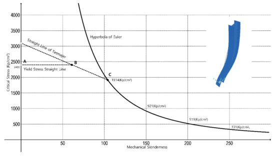
[9], having gone through a deep study of a great many experimental results, proposed a diagram for the critical buckling of steel, the most widely applied at the time in Germany and middle Europe, the A-37, whose yield stress was in the order of 240 MPa (2400 kp/cm
2). When the members presented mechanical slenderness greater than 105, Euler’s equation was to be applied directly, since Euler’s hyperbola application limit is defined as
When the members are characterized by a mechanical slenderness that falls between 0 and 105, the straight line of Tetmajer was proposed (Figure 1) by regression of his experimental data, which, in stress units of kp and cm squared, is the following:
Figure 1. Basic diagram to show buckling of steel columns in the light of Euler’s equation, the yield stress of steel, and Tetmajer’s later equation.
Equation (16) is known as Euler–Tetmajer. Tetmajer also proposed a more elaborated parabolic expression to account for this area of buckling.
Around this time, in 1889, the researchers Considère and Engesser advanced separately that in Euler’s Equation (4), and for slenderness less than 100, the Young’s modulus to be used was to be less than the actual one, which they termed as effective modulus “Eeff” and tangent modulus “Et”, respectively, to predict the behavior of the compressed member in the nonelastic zone, where Euler’s equation cannot apply.
About two decades later (1910), von Karman suggested his well-known double-modulus
ER theory founded on Engesser’s theory and Considere’s idea
[10].
Southwell (1914) introduced the concept of initial deformations in straight pieces under compression, in order to infer a first Euler load on the column
[11].
Sometime later, in 1928, German standards for metallic construction stated that for steel type A-37 of yield stress 2400 Kp/cm2, the stress–mechanical slenderness diagram in Figure 1, which happens to be Tetmajer’s with some modification, was to be applied. The precise values of the mechanical slenderness in the points B and C of the diagram are exactly 61.4 and 104, respectively. The German legislation reporters rounded off to 60 and 100, with sound criteria. With Tetmajer’s contributions, the design and calculation of slender steel columns subjected to centered compression advanced by leaps and bounds.
To bring to an end this historical overview on equations for the design of slender steel column buckling, Timoshenko’s secant method formula needs to be noted, deduced forthright from his
Materials Resistance [8]. The secant formula in today’s terms would be as follows:
where the meanings of which are
σmax Steel yield stress (fy).
σc Maximum compression stress which depletes the column.
e Load eccentricity caused by the flexural momentum acting on the section, measured in relation to the section’s center of gravity.
c Section’s center of gravity distance with respect to the most compressed fiber, for symmetric sections c = h/2 (half the section’s edge).
E Longitudinal elasticity modulus of the column’s material. The Young’s Modulus.
r Radius of gyration of the section with respect to the buckling axis.
L Buckling length of the member.
The secant method formula has basically two shortcomings when applied to a slender steel column subjected to central compression. The first problem is that the equation is transcendent, i.e., the value of “σc” must be obtained by successive numerical approximations. The second is that in cases when there is no exterior flexural moment applied to the section, there will be no eccentricity: “e = 0”, and so the formula cannot work. In such circumstance, Euler’s equation must be used straightforwardly. A possible solution to this problem—and only for columns subjected to central compression—could be that eccentricity equaled the initial geometric imperfection of the column, either “e = L/500 or e = L/300”, depending on the manufacturing and assembly tolerances. Finally, the type of section must be defined, as the secant method formula requires that the parameter’s value “c” be defined.
In the case of plate buckling, the earliest attempts were made by Bleich (1924),
[12] who suggested the replacement of Young’s modulus in the elastic critical buckling stress of plates by a reduced modulus such as the tangent modulus or the secant modulus.
Using the Engesser–von Karman methods for the inelastic buckling of columns, and with reference to the buckling of stocky plates beyond the proportional limit, Lundquist (1939) was the first who derived the buckling equation for plates
[13].
The axially loaded steel I-section column has a tendency to buckle by twisting on its own axis. In the case of thin-wall sections of certain cross section and length, twisting buckling may occur at lower loads than the bending or Euler buckling. This type of buckling was studied by Kappus (1938)
[14].
Based on Wagner and Kappus theories, Goodier, in 1941
[15], investigated the behavior of columns which are torsionally weak. In 1946, Shanley stated that the tangent modulus
Et is the correct effective modulus to be employed for buckling beyond the proportional limit and that the unloading of one side of the column does not occur until the tangent modulus load is reached
[16][17].
3. The First Construction Standards
It was in the year 1952 that the German standard DIN 4114
[18] introduced the concepts of buckling coefficient “ω” in the form of a table for the various types of steel existing at the time: the A-37 and the A-52. It also defined the concept of length of buckling in terms that practically have not changed today. The concept of buckling coefficients, “
ω”, however, had already been proposed by the French researcher J. Dutheil
[19] sometime around the year 1947.
In 1952 the German standards criteria were introduced in Spain, and then in the year 1962, the Spanish EM-62
[20] came to life, which, in its 1969 version, proposes the very same concepts for the buckling coefficient “
ω” and for the length of buckling “
Lk”.
In the year 1972, the standard MV-103
[21] was published in Spain. This standard broadens and improves the previous EM-62 in issues related to the design and calculation of buckling in simple steel columns subjected to centered compression—which happens to be the same as that named NBE-EA-95
[22] that appeared in 1995. This standard, MV-103, stood the passage of time well into the year 2006, when it was superseded by the CTE-DB SE A (Steel)
[23].
Both Spanish standards, the MV-103 and the NBE-EA-95, introduced nondimensional coefficients for buckling “ω”; coefficients greater than the unit, arranged in three tables for the three types of steel currently in existence in Spain: A-37, A-42, and A-52, each of which show a yield stress of 2400, 2600, and 3600 Kp/cm2, respectively.
In standards MV-103 and NBE-EA-95, the buckling test is carried out by satisfying the following inequality:
where
P* Maximum design load the column can withstand.
ω Nondimensional buckling coefficient greater than or equal to the unit, a function of the type of steel, yield stress, and mechanical slenderness of the member.
A Gross cross-sectional area.
σadm Tolerable steel strength equal to its yield stress.
The mechanical slenderness is a function of the buckling length and the radius of gyration with respect to the buckling axis or buckling plane. The buckling coefficients “ω” of previous Spanish standards, MV-103 and NBE-EA-95, can, not only readily but also exactly, be obtained through numerical calculations rather than through the proposed tables in the standards, applying the following expressions:
where
λk Mechanical slenderness of the column.
E Modulus of longitudinal elasticity of the material the column is made of. The Young’s modulus.
a, b Nondimensional auxiliary coefficients.
ω Nondimensional buckling coefficient greater than or equal to the unit, a function of the type of steel, yield stress, and mechanical slenderness of the member.
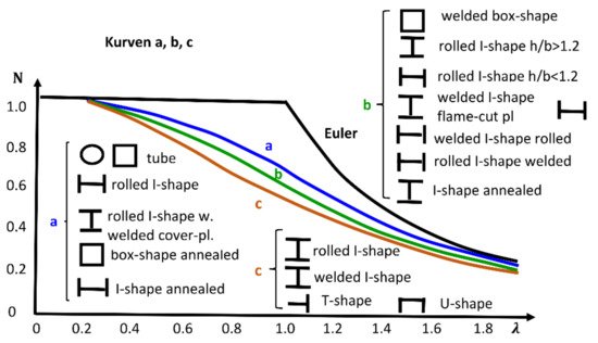
In the year 1976, the
Manual on Stability of Steel Structures [24] published a series of buckling curves, where the ordinate axis showed the axial load related to the yield load and, in the abscissas axis, the slenderness ratio (
Figure 2). These curves were obtained after the analysis of 1067 compression column tests performed in seven European countries (Belgium, France, Germany, Italy, Netherlands, United Kingdom, and Yugoslavia). The test program included various types of members (I,H,T, round, and square hollow sections) and it covered the range of slenderness ratios most frequently used in European constructional practice (55, 75, 95, 130, and 160). Later, a complementary program was carried out at Lehigh University on columns of relatively heavier sections, and the conclusions were used for establishing the buckling curves.
Figure 2. Buckling curves published in
Manual of Stability of Steel Structures [24].
There was a total of three curves. Each one was valid for a certain type of section, and they considered whether the section was welded or rolled. The document gave parameters to transform those buckling curves to consider the dependence of their magnitude from the thickness of the compressed parts of the cross sections in buckling direction. Besides, the documents considered yield stress reduction factors based on geometrical characteristics of the cross sections as, for example, if the section had welded flange cover plates.
4. Operative Standards, Current Situation
Current European operative standards state that metallic members exhibiting simple cross section and centered compressive stress should verify Equation (22) so as not to undergo buckling.

where
Nb,Rd Design buckling resistance of a compression member.
NEd Design value of the compression force.
χ Buckling coefficient less than or equal to the unit, a function of the imperfection factor and of the member’s reduced slenderness.
A Gross cross-sectional area.
fyd Design yield stress.
The nondimensional buckling coefficient “χ” can be obtained, applying


where
χ Nondimensional buckling coefficient less than or equal to the unit, a function of the member’s imperfection factor and reduced slenderness.
λ Member’s reduced slenderness with respect to the selected axis. It should be less than or equal to 3.
α Imperfection factor, dependent on the type of cross section and buckling axis.
I Cross-sectional inertia dependent on the selected axis.
A Gross cross-sectional area.
Lk Buckling length of the column.
fy Yield stress of steel.
The ratio between reduced slenderness and mechanical slenderness of a member can readily be obtained when the following equation is applied:

The reduced slenderness “λ” is the square root of the coefficient “a” in Equation (19), and the coefficient “ϕ” matches roughly with the coefficient “b” in Equation (20). Therefore, the buckling coefficient “χ” is approximately the inverse of the buckling coefficient “ω” present in the Spanish standards MV and NBE for steel, already superseded, with the exception of the imperfection factor “α” in current operative standards, where five buckling curves, not the single one previously advanced, are proposed.
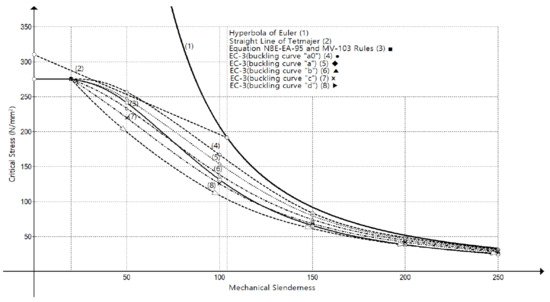
Figure 3 shows the ratio between compressive strength and mechanical slenderness for buckling steel columns proposed by current EC-3
[25], and by previous standards—already in disuse—together with Euler’s ideal hyperbola and Tetmajer’s experimental right line.
Figure 3. Strength–mechanical slenderness ratio diagram. Comparing different models from Spanish buckling standards for slender steel columns.
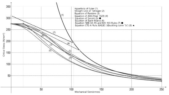
In Figure 4, the most representative historical standards using the same acceptable stress parameters of steel are grafted to compare column behavior when the strength is reduced while the slenderness is increased.
Figure 4. Strength–mechanical slenderness graph. Comparison between past and current models for slender steel column buckling.
The type of steel selected is the current 275, exhibiting a yield stress of 275 N/mm2, ignoring any safety coefficient to avoid conflicts among the different standards.
Regarding American design codes, the American Institute of Steel Construction published specifications for structural steel buildings
[7]. The main expression for buckling of nonslender elements under axial compression is


where
E Modulus of elasticity of steel.
Fe Elastic buckling stress through an elastic buckling analysis .
Fy Specified minimum yield stress of the type of steel being used.
r Radius of gyration.
Lc Effective length of the member for buckling about the minor axis.
The Chinese “Code for Design of Steel Structures” [26] offers an expression for solid web beam columns, subjected to combined axial load and bending:

where
N Axial compression in the calculated portion of the member.
N’Ex Parameter, N’Ex = π2EA/(1.1 λx2).
φx Stability factor of axial compression members buckling in the plane of bending.
Mx Maximum moment in the calculated portion of the member.
W1x Gross section modulus referred to the more compressed fiber in the plane of bending.
Βmx Factor of equivalent moment, taken between 0.65–1.00.
f Yield stress.
5. Conclusions
Having considered the different arguments, the following ideas can safely be emphasized:
-
Buckling is a transcendent phenomenon for the safety of building and bridge structures. Buckling problems must be considered in the design, calculation, and construction phase of the structures.
-
Every model is below Euler–Tetmajer’s equations, with the exception of that of AISC
[7], proposed in 1921, which, for slenderness greater than 120, Euler’s equation
[27] applies.
-
Euler’s equation
[27] has been applied in structural mechanics for almost 300 years with barely any modification. The fact that it is still being applied today makes it the most long-lived equation in structural engineering.
-
Every model predicts that for mechanical slenderness of approximately 20, the member will not undergo the process of buckling.
-
In practice, the differences that exist between standard MV 103
[21] (NBE EA 95
[22]) and standard CTE DB SE A, EAE, and EC-3
[23][28][25] are relatively small.
-
The secant method formula yield values very much in line with those proposed by the standards.
-
Rankine’s
[6] and AISC
[7] models yield values in line with those much more elaborated coming afterwards for mechanical slenderness of less than 100. Specifically, Rankine’s equation, even though old, is in tune with all the mechanical slenderness values predicted by much more sophisticated modern models.
-
Older models, such as Barré–Marvá’s
[4], yield more conservative values, somehow far from today’s actual values but quite acceptable nonetheless. The reason could well reside in the fact that those values were to be applied to cast iron columns that exhibited less slenderness than those used later.
-
According to the performed numerical simulations, older models, such as Euler
[27], Tetmajer
[9], Rankine
[6], and AISC
[7], tend to slightly overestimate the critical buckling stress for high slenderness ratios from around 100 (except Euler, which considerably overestimates the critical stress for low and mid-slenderness ratios because it does not consider the nonlinear behavior of the steel when the yielding takes place). Besides, the Tetmajer
[9] model also overestimates critical buckling stress for low slendernesses below approximately 30.
-
The order of the theoretical curves, considering their degree of overestimation of the critical buckling stress, is (1) Euler
[27], (2) Tetmajer
[9], (3) Rankine
[6], (4) Timoshenko’s secant
[8], (5) Barré–Marvá
[4]. From a design point of view, Timoshenko’s secant
[8] and Barré–Marvá
[4] curves are on the safe side for any value of mechanical slenderness according to the finite element model results.
-
Design code models such as CTE-A, EAE and EC-3 models
[23][28][25], MV-103
[21], and NBE EA 95 model
[22], generally underestimate the critical buckling stress for any slenderness ratio according to the numerical simulations. CTE-A, EAE, and EC-3 models
[23][28][25] show the most accurate results.
This entry is adapted from the peer-reviewed paper 10.3390/ijerph182212253


