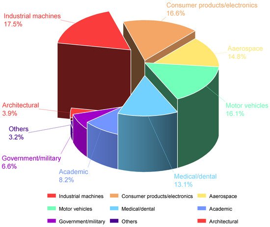
Additive manufacturing technologies, well known as three-dimensional printing (3DP) technologies, have been applied in many industrial fields, including aerospace, automobiles, shipbuilding, civil engineering and nuclear power. However, despite the high material utilization and the ability to rapidly construct complex shaped structures of 3D printing technologies, the application of additive manufacturing technologies in railway track infrastructure is still at the exploratory stage.
- 3D printing
- additive manufacturing
- railway track
- railway infrastructure
1. Introduction

2. Additive Manufacturing in Railway Components
2.1. Rails
| Reference | Base Material of Powders | Powder Type |
|---|---|---|
| Lai et al. (2019) [40] | Fe-based | 410L, 420SS |
| Co-based | Stellite 6, Stellite 21 | |
| Lu et al. (2019) [66] | Fe-based | martensitic stainless steel (MSS) |
| Roy et al. (2018–2020) [55][56][57][58][59][60][61][62][63][64][65][66][67] | Fe-based | 410L, 420SS |
| Co-based | Stellite 6 | |
| Fu et al. (2015) [43] | Fe-based | martensitic stainless steel (MSS) |
| Zhu et al. (2019) [68] | Fe-based | 316L, 410L, 420L |
| Lewis et al. (2015–2017) [52][69][70] | Fe-based | Hadfield, martensitic stainless steel (MSS), 316 Stainless |
| Co-based | Stellite 6 | |
| Narayanan et al. (2019) [71] | Fe-based | a premium martensitic stainless steel |
| Meng et al. (2019) [50][57] | Ni-based | Not mentioned |
| Wang et al. (2017–2018) [35][36][53] | Fe-based | AISI316L stainless steel produced by Höganäs |
| Seo et al. (2019) [12] | Co-based | Stellite 21 |
| Ni-based | Inconel 625, Hastelloy C | |
| Clare et al. (2012) [47] | Ni-based | Stellite 6 |
| Guo et al. (2015) [24] | Co-based | Not mentioned |
| Wang et al. (2014) [48] | Co-based | Not mentioned |
| Aladesanmi et al. (2019) [72] | Others | Ti, TiB2 |
2.2. Fasteners

2.3. Sleepers

2.4. Supporting Layers

2.5. Special Components
3. Challenges
Even though additive manufacturing technologies have many advantages and have been applied in some civil buildings and lightweight structures for aerospace fields, the application of 3D printing in railway engineering is still in the explosion stage. This is due to the limitations as follows.
3.1. Reliability
The materials used for 3D printing can be classified into three main types, including polymer materials (e.g., photosensitive resin, thermoplastic polymer and hydrogels), metallic materials(e.g., Fe-based, Ti-based, Co-based, Cu-based alloys and etc.) and ceramic materials(e.g., cement materials, clay materials and silicate glass materials)[135][136]. Even though those materials can be 3D printed in complex shapes by different additive manufacturing processes, the mechanical properties of many 3D printed samples are usually less than casting samples due to the error in the 3D printing process[137]. Conventional railway track infrastructure is of simple geometric shapes and can be produced easily with well-developed conventional railway construction methods.
Moreover, many additive manufacturing technology processes include heating(melting) and cooling processes, which result in uneven deformation and residual stress inside the 3D printed samples. Other printing processes may also produce defects in 3D printed samples, such as small voids (bubbles) and microcracks. These defects will decrease the strength and life cycle of printed samples. The mechanical performance of 3D printed samples is greatly affected by printing speed, printing orientation, printing temperature, etc.[138]. However, there is no specific standards for 3D printing samples to ensure the 3D printed sample quality. This uncertainty of 3D printed samples hinders the use of 3D printing technology in railway engineering fields. Many 3D printed samples have rough surfaces due to the poorer accuracy than casting mould methods [136]. When additive manufacturing technology is adopted to produce an enhanced layer on the top of rails, grinding and polishing processes are compulsory for making a smooth surface. These processes are time-consuming.
Most importantly, the railway track infrastructure is required to have good fatigue performance under long-term moving train loads[139]. Most 3D printed samples are tested under static and quasi-static loads; the behaviours of 3D printed samples under dynamic loads and long-term loads have not been fully understood yet, which may result in the risk of failure of the railway system under long-term service.
In general, the risk in reliability of 3D printing components in railway engineering is caused by poor raw material properties and 3D printing defects. The development of 3D printable materials, technologies and standards will gradually solve the reliability problems of 3D printing in railway track infrastructures.
3.2. Size and Space Limitation
The size limitations of different 3D printing technologies are different. The maximum size of 3D printed metallic, and polymer samples are usually less than 1 m, which is limited by the size of 3D printing machines. The length of railway sleepers is 2.6 m, and the width of ballast beds and slab tracks are more than 2.6 m[102]. It is not easy to use 3D printing to manufacture all-in-one large-size composite sleepers or track supporting.
3D printing concrete technology allows large size 3D printed constructions, such as 3D printed civil buildings and bridges, but the printing equipment (e.g., robotic arm and removable tracks) needs to be put on-site[140][141]. The land areas of 3D printed houses and bridges are in the order of hundreds of square meters, and the construction site is mostly located in downtown areas on plate ground. Unlike these infrastructures, the length of railway lines is much greater, and much railway infrastructure is located on mountain tunnels, underground tunnels, bridges, and in open suburbs. The field conditions make the preparation and placement of 3D printing machines difficult.
3.3. Cost
The qualitative comparison of the average cost of fabricating products between 3D printing technology and conventional manufacturing technology is present in Figure 15. The average cost of products fabricated using conventional subtractive manufacturing methods (e.g., CNC) increases when the product complexity increases or when the product quantity decreases. This is because manufacturing products with complex shapes by subtractive technology needs complicated processes (e.g., cutting, drilling and milling). The average cost of 3D printing technologies is not sensitive to product complexity and quantity. Thus, 3D printing technologies show excellent prospects for a small quantity of complex products. However, the geometric shape of railway track infrastructure components is simple, and the demand for railway components for constructing a railway line is massive. This means that using conventional subtractive manufacturing technologies to build railway infrastructures is cheaper than 3D printing technologies, which hinders 3D printing in railway infrastructures.
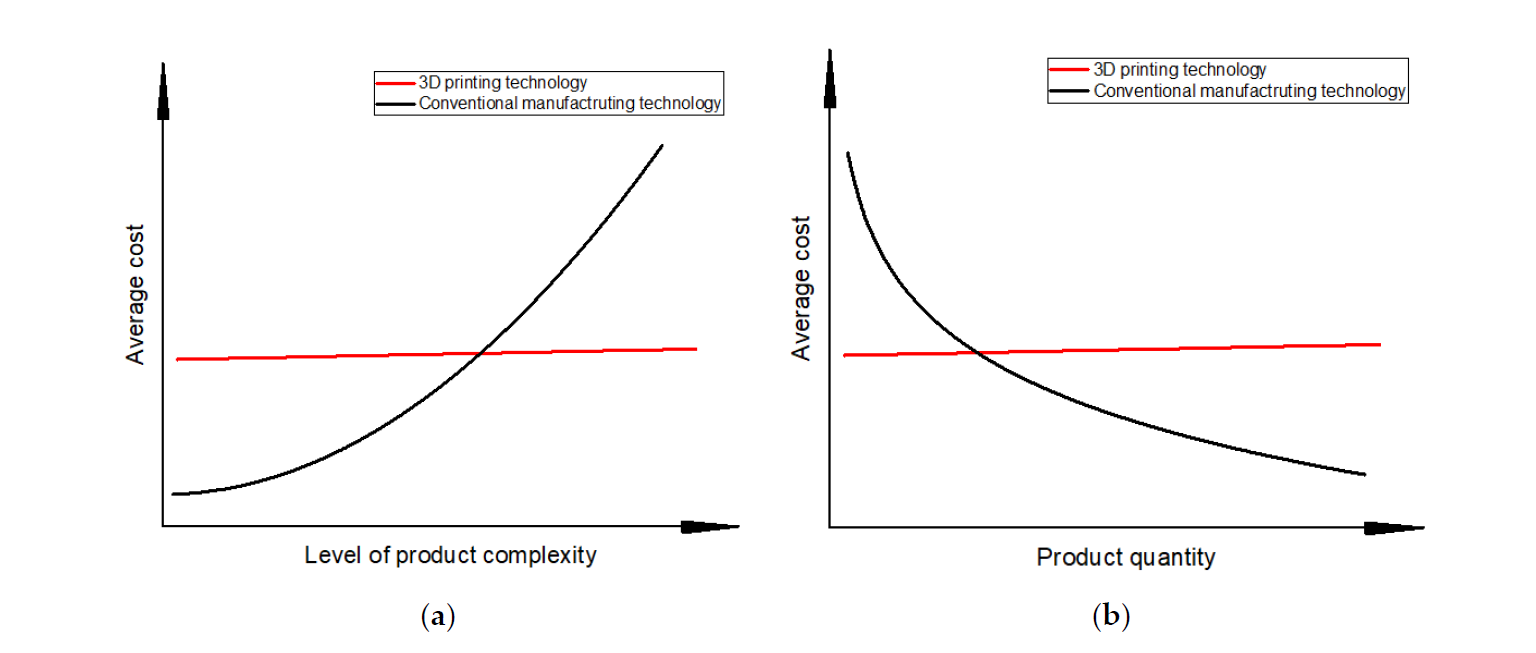
Figure 15. Qualitative comparison of costs between 3D printing technology and conventional manufacturing technology. (a) cost of the level of product complexity; (b) cost of the product quantity.
4. Perspectives
Based on the previous study, the highlight findings and the knowledge gap of 3D printing application in railway track infrastructures can be described well in Table 2.
Table 2. Summary of 3D printing application and research in railway track infrastructure.
|
Components |
Highlight Finding |
Knowledge Gap |
|
Rails |
3D printing technologies can be used to repair and enhance rails by generating an enhanced layer on the railhead area. The hardness and fatigue performance can be improved. The failure modes of 3D printed composite rails will change when the fiber contents changes. |
No study uses 3D printing technologies to fabricate a full rail with metallic materials. Also, the mechanical properties of 3D printed composite rails are poor. The 3D printing technologies about metallic materials still need to be improved. The future study can produce a full rail with metals and improve the mechanical properties of 3D printed composite rail by adding different materials with high strength. |
|
Fasteners |
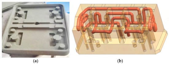
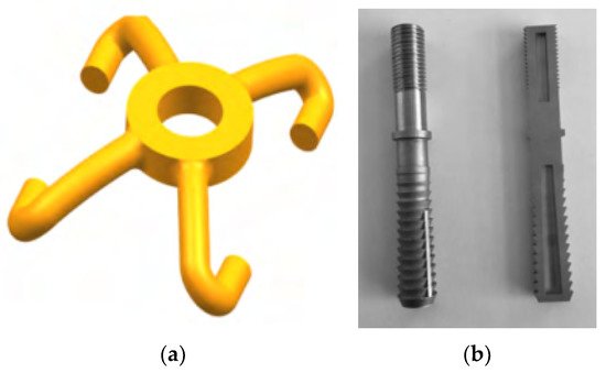
3D printing can reduce the fabricating time of steel plates by mould optimization. 3D printing allows the production of structures with complex geometric shapes. |
There is no fastener component directly fabricated using 3D printing. The clips and the rail pads can be designed and produced with smart shape and high damping porous structures such as honeycomb, lattice and TPMS structures. |
|
Sleepers (bearers) |
Composite sleepers (bearers) can be produced with multiply layers using 3D printing technologies. The shape of sleepers(bearers) can be optimised for saving materials and improving track performance. |
The research about combining different materials in composite sleepers (bearers) is limited, and the shapes of sleepers (bearers) are simple. Future research can try 3D printed sleepers (bearers) with multi-materials, multi-layers and optimised shapes. |
|
Supporting layers |
3D printed smart rocks with internal sensors can help detect the dynamic responses of ballast particles in the ballasted track on sites. 3D printing concrete technologies can be used to construct concrete slabs. |
There are limited studies about designing 3D printable one-in-all track support. The research about 3D printed track supports with smart structures can be carried out. |
|
Special components |
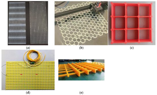
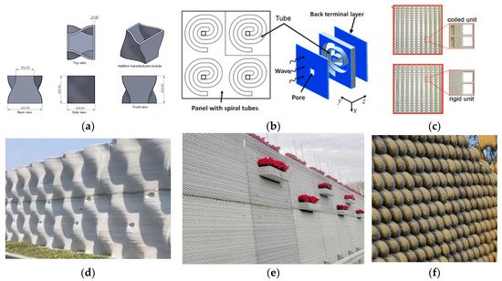
3D printing technologies have already been used to produce concrete sound-proof walls, composite geogrids, and geocells. |
The studies about the performance of 3D printed sound-proof walls and geogrids/geocells under actual railway loads are scarce. Future studies can focus on the dynamic responses of 3D printed components under railway loads. |
Based on the present research of 3D printing in railway engineering and the pros and cons of additive manufacturing technology, the prospects of 3DP technologies in railway engineering are concluded as the following aspects:
- 3D printing technologies can help optimize and construct small components of railway infrastructures, e.g., fastener components (clips, screw spikes and rail pads), geogrids and geocells.
- The rail can be enhanced by additive manufacturing technologies. The approach can help lengthen the life cycle of railway turnout systems by increasing the fatigue behaviour of rails (including stock rails, closure rails, wing rails and guardrails). With the development of new printable metallic and polymer materials, the rails can be fabricated with good mechanical properties using 3D printing technologies.
- 3D printing technologies have the potentials to be used in fabricating composite sleepers (bearers) with multi-layers and producing sleepers with complex shapes.
- 3D printed concrete technologies are well-developed and can be used to construct sound barriers in railway engineering. 3D printing concrete slab track is being prepared in the UK.
- Smart track detection methods can be developed using 3D printing technologies help to detect the track dynamic response in real-time.
The 3D printing technologies enable the fabrication of an ultra-high-speed tube track system (also called hyperloop), which allows the train to speed up to 1200km/h. Figure 16 indicates an initial conceptual design of the prototype hyperloop railway structure. Moreover, all-in-one track supports can be designed with a gradient density in accordance with the stress distribution inside the railway track support. The track stiffness is designable by changing the porosity and structural form of the all-in-one structures. The all-in-one track supports with gradient porosity will have a gradient track stiffness, which can help solve the problem of discontinuous stiffness in the transition areas.
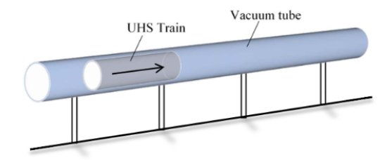
Figure 16. A conceptual design of hyperloop track system[142].
5. Conclusions
This paper presents an overview of 3D printing application and research in railway track infrastructures and the challenges and perspectives of 3D printed railway tracks. The main benefits of additive manufacturing technologies are fabricating complex objects, saving materials, reducing carbon emission, and shortening the product production cycle. The recent research and application of additive manufacturing (3DP) technologies in railway track infrastructures have been reviewed. Presently, the 3DP in railway infrastructures is still in the exploration stage; only the laser melting methods for enhancing rail and wheel surfaces are well developed. This is due to the poor reliability and other limitations of 3D printing technologies for railway engineering. However, 3D printing shows excellent prospects in building all-in-one track infrastructures and designing transition zone supports. In the future, with the development of 3D printing materials, technologies and standards, additive manufacturing will be adopted for building smart railway track infrastructures. This research can promote the research and application of 3D printing in railway engineering.
Author Contribution
Author Contributions: Conceptualization, H.F. and S.K.; writing—original draft preparation, H.F.; writing— review and editing, H.F. and S.K.; graphics and visualization, H.F.; project administration, S.K.; funding acquisition, H.F. and S.K. All authors have read and agreed to the published version of the manuscript.
: The research was partially funded by the China Scholarship Council and the European Commission for H2020-MSCA-RISE Project No. 691135 “RISEN: Rail Infrastructure Systems Engineering Network,” which enables a global research network that tackles the grand challenge in railway infrastructure resilience and advanced sensing under extreme conditions[143].
Conflicts of Interest: The authors declare no conflict of interest.
This entry is adapted from the peer-reviewed paper 10.3390/jcs6010007
References
- Debrezion, G.; Pels, E.; Rietveld, P. The impact of railway stations on residential and commercial property value: A meta-analysis. J. Real Estate Financ. Econ. 2007, 35, 161–180.
- Kaewunruen, S.; Remennikov, A.M. Dynamic properties of railway track and its components: A state-of-the-art review. New Res. Acoust. 2008, 28, 197–220.
- Remennikov, A.M.; Kaewunruen, S. A review of loading conditions for railway track structures due to train and track vertical interaction. Struct. Control Health Monit. 2008, 15, 207–234.
- Kaewunruen, S.; Remennikov, A.M. Current state of practice in railway track vibration isolation: An Australian overview. Aust. J. Civ. Eng. 2016, 14, 63–71.
- Gautier, P.E. Slab track: Review of existing systems and optimization potentials including very high speed. Constr. Build. Mater. 2015, 92, 9–15.
- Tatsuoka, F.; Tateyama, M.; Koda, M.; Koseki, J. Seismic Design, Construction and Performance of Geosynthetic-Reinforced Soil Retaining Walls and Bridge Abutments for Railways in Japan. In Proceedings of the 2013 Geo-Congress, San Diego, CA, USA, 3–7 March 2013.
- Brown, S.F.; Kwan, J.; Thom, N.H. Identifying the key parameters that influence geogrid reinforcement of railway ballast. Geotext. Geomembr. 2007, 25, 326–335.
- Lee, H.P.; Lim, K.M.; Kumar, S. Noise assessment of elevated rapid transit railway lines and acoustic performance comparison of different noise barriers for mitigation of elevated railway tracks noise. Appl. Acoust. 2021, 183, 108340.
- Mehdipour, R.; Baniamerian, Z. A new approach in reducing sand deposition on railway tracks to improve transportation. Aeolian Res. 2019, 41, 100537.
- Zhong, W.; Hu, J.J.; Shen, P.; Wang, C.Y.; Lius, Q.Y. Experimental investigation between rolling contact fatigue and wear of high-speed and heavy-haul railway and selection of rail material. Wear 2011, 271, 2485–2493.
- Tsunashima, H. Condition Monitoring of Railway Tracks from Car-Body Vibration Using a Machine Learning Technique. Appl. Sci. 2019, 9, 2734.
- Seo, J.-W.; Kim, J.C.; Kwon, S.-J.; Jun, H.-K. Effects of Laser Cladding for Repairing and Improving Wear of Rails. Int. J. Precis. Eng. Manuf. 2019, 20, 1207–1217.
- Guo, Y.; Markine, V.; Zhang, X.; Qiang, W.; Jing, G. Image analysis for morphology, rheology and degradation study of railway ballast: A review. Transp. Geotech. 2019, 18, 173–211.
- Li, Y.; Trinh, H.; Haas, N.; Otto, C.; Pankanti, S. Rail Component Detection, Optimization, and Assessment for Automatic Rail Track Inspection. IEEE Trans. Intell. Transp. Syst. 2014, 15, 760–770.
- Ferdous, W.; Manalo, A.; Van Erp, G.; Aravinthan, T.; Ghabraie, K. Evaluation of an Innovative Composite Railway Sleeper for a Narrow-Gauge Track under Static Load. J. Compos. Constr. 2018, 22, 04017050.
- Attaran, M. The rise of 3-D printing: The advantages of additive manufacturing over traditional manufacturing. Bus. Horiz. 2017, 60, 677–688.
- Lipson, H.; Kurman, M. Fabricated: The New World of 3D Printing; John Wiley & Sons: Hoboken, NJ, USA, 2013; Available online: https://www.wiley.com/en-gb/Fabricated%3A+The+New+World+of+3D+Printing-p-9781118416945 (accessed on 6 December 2021).
- ASTM F2792-12aStandard Terminology for Additive Manufacturing Technologies, ASTM International: Montgomery, PA, USA, 2012. Available online: https://web.mit.edu/2.810/www/files/readings/AdditiveManufacturingTerminology.pdf(accessed on 6 December 2021).
- Bortolini, M.; Calabrese, F.; Galizia, F.G.; Mora, C.; Ventura, V. Industry 4.0 Technologies: A Cross-sector Industry-Based Analysis. In Sustainable Design and Manufacturing, Proceedings of the 8th International Conference on Sustainable Design and Manufacturing (KES-SDM 2021), Split, Croatia, 15–17 September 2021; Springer: Singapore, 2021.
- Gräbe, H.; Mpye, D.; Vandoorne, R.; Broekman, A.; Pienaar, D.; Hawley, C.; van Schalkwyk, H. Advancing the digital railway with 4IR technologies. Civ. Eng. Siviele Ing. 2021, 29, 30–35.
- Shahrubudin, N.; Lee, T.C.; Ramlan, R. An overview on 3D printing technology: Technological, materials, and applications. Procedia Manuf. 2019, 35, 1286–1296.
- Kianian, B. Wohlers Report 2017: 3D Printing and Additive Manufacturing State of the Industry, Annual Worldwide Progress Report; Wohlers Associates, Inc.: Fort Collins, CO, USA, 2017; Available online: https://portal.research.lu.se/en/publications/wohlers-report-2017-3d-printing-and-additive-manufacturing-state- (accessed on 6 December 2021).
- Kwon, Y.M.; Lee, Y.-A.; Kim, S.J. Case study on 3D printing education in fashion design coursework. Fash. Text. 2017, 4, 26.
- Guo, H.-M.; Wang, Q.; Wang, W.-J.; Guo, J.; Liu, Q.-Y.; Zhu, M.-H. Investigation on wear and damage performance of laser cladding Co-based alloy on single wheel or rail material. Wear 2015, 328–329, 329–337.
- Biazon, L.; Ferrer, B.P.; Toro, A.; Cousseau, T. Correlations between rail grease formulation and friction, wear and RCF of a wheel/rail tribological pair. Tribol. Int. 2021, 153, 106566.
- Ringsberg, J.W.; Bjarnehed, H.; Johansson, A.; Josefson, B.L. Rolling contact fatigue of rails—Finite element modelling of residual stresses, strains and crack initiation. Proc. Inst. Mech. Eng. Part F J. Rail Rapid Transit. 2000, 214, 7–19.
- Ringsberg, J.W.; Skyttebol, A.; Josefson, B.L. Investigation of the rolling contact fatigue resistance of laser cladded twin-disc specimens: FE simulation of laser cladding, grinding and a twin-disc test. Int. J. Fatigue 2005, 27, 702–714.
- Zerbst, U.; Lundén, R.; Edel, K.O.; Smith, R.A. Introduction to the damage tolerance behaviour of railway rails—A review. Eng. Fract. Mech. 2009, 76, 2563–2601.
- Wang, X.; Lei, L.; Yu, H. A Review on Microstructural Features and Mechanical Properties of Wheels/Rails Cladded by Laser Cladding. Micromachines 2021, 12, 152.
- Hiensch, M.; Larsson, P.-O.; Nilsson, O.; Levy, D.; Kapoor, A.; Franklin, F.; Nielsen, J.; Ringsberg, J.W.; Josefson, B.L. Two-material rail development: Field test results regarding rolling contact fatigue and squeal noise behaviour. Wear 2005, 258, 964–972.
- Franklin, F.J.; Weeda, G.J.; Kapoor, A.; Hiensch, E.J.M. Rolling contact fatigue and wear behaviour of the infrastar two-material rail. Wear 2005, 258, 1048–1054.
- Hiensch, E.J.M.; Franklin, F.J.; Nielsen, J.C.O.; Ringsberg, J.W.; Weeda, G.J.; Kapoor, A.; Josefson, B.L. Prevention of RCF damage in curved track through development of the INFRA-STAR two-material rail. Fatigue Fract. Eng. Mater. Struct. 2003, 26, 1007–1017.
- Hiensch, M.; Kapoor, A.; Josefson, B.L.; Ringsberg, J.W.; Nielsen, J.; Franklin, F.J. Two-Material Rail Development to Prevent Rolling Contact Fatigue and Reduce Noise Levels in Curved Rail Track. In Proceedings of the 5th World Congress on Railway Research: WCRR 2001, Cologne, Germany, 25–29 November 2001; Available online: http://www.railway-research.org/IMG/pdf/112.pdf (accessed on 6 December 2021).
- Vilar, R. Laser cladding. J. Laser Appl. 1999, 11, 64–79.
- Wang, X.; Deng, D.; Zhang, H. Effects of mass energy and line mass on characteristics of the direct laser fabrication parts. Rapid Prototyp. J. 2018, 24, 270–275.
- Wang, X.; Deng, D.; Hu, Y.; Ning, F.; Wang, H.; Cong, W.; Zhang, H. Overhang structure and accuracy in laser engineered net shaping of Fe-Cr steel. Opt. Laser Technol. 2018, 106, 357–365.
- Thawari, N.; Gullipalli, C.; Chandak, A.; Gupta, T.V.K. Influence of laser cladding parameters on distortion, thermal history and melt pool behaviour in multi-layer deposition of stellite 6: In-situ measurement. J. Alloys Compd. 2021, 860, 157894.
- Shamsaei, N.; Yadollahi, A.; Bian, L.; Thompson, S.M. An overview of Direct Laser Deposition for additive manufacturing; Part II: Mechanical behavior, process parameter optimization and control. Addit. Manuf. 2015, 8, 12–35.
- Zhu, G.; Li, D.; Zhang, A.; Pi, G.; Tang, Y. The influence of laser and powder defocusing characteristics on the surface quality in laser direct metal deposition. Opt. Laser Technol. 2012, 44, 349–356.
- Lai, Q.; Abrahams, R.; Yan, W.; Qiu, C.; Mutton, P.; Paradowska, A.; Soodi, M.; Wu, X. Influences of depositing materials, processing parameters and heating conditions on material characteristics of laser-cladded hypereutectoid rails. J. Mater. Processing Technol. 2019, 263, 1–20.
- Hemmati, I.; Ocelík, V.; De Hosson, J.T.M. The effect of cladding speed on phase constitution and properties of AISI 431 stainless steel laser deposited coatings. Surf. Coat. Technol. 2011, 205, 5235–5239.
- Hemmati, I.; Ocelík, V.; De Hosson, J.T.M. Microstructural characterization of AISI 431 martensitic stainless steel laser-deposited coatings. J. Mater. Sci. 2011, 46, 3405–3414.
- Fu, Z.K.; Ding, H.H.; Wang, W.J.; Liu, Q.Y.; Guo, J.; Zhu, M.H. Investigation on microstructure and wear characteristic of laser cladding Fe-based alloy on wheel/rail materials. Wear 2015, 330–331, 592–599.
- Selcuk, C. Laser metal deposition for powder metallurgy parts. Powder Metall. 2011, 54, 94–99.
- Zhou, S.; Dai, X.; Zheng, H. Microstructure and wear resistance of Fe-based WC coating by multi-track overlapping laser induction hybrid rapid cladding. Opt. Laser Technol. 2012, 44, 190–197.
- Navas, C.; Cadenas, M.; Cuetos, J.M.; de Damborenea, J. Microstructure and sliding wear behaviour of Tribaloy T-800 coatings deposited by laser cladding. Wear 2006, 260, 838–846.
- Clare, A.; Oyelola, O.; Folkes, J.; Farayibi, P. Laser cladding for railway repair and preventative maintenance. J. Laser Appl. 2012, 24, 032004.
- Wang, W.J.; Hu, J.; Guo, J.; Liu, Q.Y.; Zhu, M.H. Effect of laser cladding on wear and damage behaviors of heavy-haul wheel/rail materials. Wear 2014, 311, 130–136.
- Niederhauser, S.; Karlsson, B. Fatigue behaviour of Co–Cr laser cladded steel plates for railway applications. Wear 2005, 258, 1156–1164.
- Meng, L.; Zhao, W.; Hou, K.; Kou, D.; Yuan, Z.; Zhang, X.; Xu, J.; Hu, Q.; Wang, D.; Zeng, X. A comparison of microstructure and mechanical properties of laser cladding and laser-induction hybrid cladding coatings on full-scale rail. Mater. Sci. Eng. A 2019, 748, 1–15.
- Jin, Y.; Ishida, M.; Namura, A. Experimental simulation and prediction of wear of wheel flange and rail gauge corner. Wear 2011, 271, 259–267.
- Lewis, S.R.; Lewis, R.; Fletcher, D.I. Assessment of laser cladding as an option for repairing/enhancing rails. Wear 2015, 330–331, 581–591.
- Wang, X.; Deng, D.; Yi, H.; Xu, H.; Yang, S.; Zhang, H. Influences of pulse laser parameters on properties of AISI316L stainless steel thin-walled part by laser material deposition. Opt. Laser Technol. 2017, 92, 5–14.
- Wang, K.; Chang, B.; Lei, Y.; Fu, H.; Lin, Y. Effect of Cobalt on Microstructure and Wear Resistance of Ni-Based Alloy Coating Fabricated by Laser Cladding. Metals 2017, 7, 551.
- Roy, T.; Paradowska, A.; Abrahams, R.; Law, M.; Mutton, P.; Soodi, M.; Yan, W. Residual stress in laser cladded heavy-haul rails investigated by neutron diffraction. J. Mater. Process. Technol. 2020, 278, 116511.
- Roy, T.; Abrahams, R.; Paradowska, A.; Lai, Q.; Mutton, P.; Soodi, M.; Fasihi, P.; Yan, W. Evaluation of the mechanical properties of laser cladded hypereutectoid steel rails. Wear 2019, 432–433, 202930.
- Meng, L.; Zeng, X.; Hou, K.; Hu, Q.; Wang, D. Effect of laser cladding and laser-induction hybrid cladding coatings on the bending properties and fracture behavior of rails. Surf. Coat. Technol. 2019, 374, 1038–1050.
- Cantini, S.; Cervello, S. The competitive role of wear and RCF: Full scale experimental assessment of artificial and natural defects in railway wheel treads. Wear 2016, 366–367, 325–337.
- Ocelík, V.; de Oliveira, U.; de Boer, M.; de Hosson, J.T.M. Thick Co-based coating on cast iron by side laser cladding: Analysis of processing conditions and coating properties. Surf. Coat. Technol. 2007, 201, 5875–5883.
- De Oliveira, U.; Ocelík, V.; De Hosson, J.T.M. Residual stress analysis in Co-based laser clad layers by laboratory X-rays and synchrotron diffraction techniques. Surf. Coat. Technol. 2006, 201, 533–542.
- Wang, W.J.; Fu, Z.K.; Cao, X.; Guo, J.; Liu, Q.Y.; Zhu, M.H. The role of lanthanum oxide on wear and contact fatigue damage resistance of laser cladding Fe-based alloy coating under oil lubrication condition. Tribol. Int. 2016, 94, 470–478.
- Duarte, V.R.; Rodrigues, T.A.; Schell, N.; Miranda, R.M.; Oliveira, J.P.; Santos, T.G. Hot forging wire and arc additive manufacturing (HF-WAAM). Addit. Manuf. 2020, 35, 101193.
- Donoghue, J.; Antonysamy, A.A.; Martina, F.; Colegrove, P.A.; Williams, S.W.; Prangnell, P.B. The effectiveness of combining rolling deformation with Wire–Arc Additive Manufacture on β-grain refinement and texture modification in Ti–6Al–4V. Mater. Charact. 2016, 114, 103–114.
- Hongxi, L.; Shengwei, J.; Yehua, J.; Xiaowei, Z.; Chuanqi, W. Microstructure and Property of Fe60 Composite Coatings by Rotating Magnetic Field Auxiliary Laser Cladding. Chin. J. Lasers 2013, 40, 0103007.
- Hu, Y.; Wang, L.; Yao, J.; Xia, H.; Li, J.; Liu, R. Effects of electromagnetic compound field on the escape behavior of pores in molten pool during laser cladding. Surf. Coat. Technol. 2020, 383, 125198.
- Lu, P.; Lewis, S.R.; Fretwell-Smith, S.; Engelberg, D.L.; Fletcher, D.I.; Lewis, R. Laser cladding of rail; the effects of depositing material on lower rail grades. Wear 2019, 438–439, 203045.
- Roy, T.; Lai, Q.; Abrahams, R.; Mutton, P.; Paradowska, A.; Soodi, M.; Yan, W. Effect of deposition material and heat treatment on wear and rolling contact fatigue of laser cladded rails. Wear 2018, 412–413, 69–81.
- Zhu, Y.; Yang, Y.; Mu, X.; Wang, W.; Yao, Z.; Yang, H. Study on wear and RCF performance of repaired damage railway wheels: Assessing laser cladding to repair local defects on wheels. Wear 2019, 430–431, 126–136.
- Lewis, S.R.; Fretwell-Smith, S.; Goodwin, P.S.; Smith, L.; Lewis, R.; Aslam, M.; Fletcher, D.I.; Murray, K.; Lambert, R. Improving rail wear and RCF performance using laser cladding. Wear 2016, 366–367, 268–278.
- Lewis, S.R.; Lewis, R.; Goodwin, P.S.; Fretwell-Smith, S.; Fletcher, D.I.; Murray, K.; Jaiswal, J. Full-scale testing of laser clad railway track; Case study—Testing for wear, bend fatigue and insulated block joint lipping integrity. Wear 2017, 376–377, 1930–1937.
- Narayanan, A.; Mostafavi, M.; Pirling, T.; Kabra, S.; Lewis, R.; Pavier, M.J.; Peel, M.J. Residual stress in laser cladded rail. Tribol. Int. 2019, 140, 105844.
- Aladesanmi, V.I.; Fatoba, O.S.; Akinlabi, E.T. Laser cladded Ti+TiB2 on Steel Rail Microstructural Effect. Procedia Manuf. 2019, 33, 709–716.
- Chen, S.-E.; Shanmugam, N.S.; Boyajian, D.; Chavan, V.S.; Weber, E.; Baarsons, K. Prototyping rail track for micro-people movers using additive manufacturing: Failure topology characterization. Constr. Build. Mater. 2021, 281, 122623.
- Gao, X.; Feng, Q.; Wang, A.; Sheng, X.; Cheng, G. Testing research on frequency-dependent characteristics of dynamic stiffness and damping for high-speed railway fastener. Eng. Fail. Anal. 2021, 129, 105689.
- Li, L.; Thompson, D.; Xie, Y.; Zhu, Q.; Luo, Y.; Lei, Z. Influence of rail fastener stiffness on railway vehicle interior noise. Appl. Acoust. 2019, 145, 69–81.
- Thompson, D.J.; Verheij, J.W. The dynamic behaviour of rail fasteners at high frequencies. Appl. Acoust. 1997, 52, 1–17.
- Mohammadzadeh, S.; Ahadi, S.; Keshavarzian, H. Assessment of fracture reliability analysis of crack growth in spring clip type Vossloh SKL14. Proc. Inst. Mech. Eng. Part O J. Risk Reliab. 2014, 228, 460–468.
- Jaroslav, S.; Lubos, P.; Vladimir, T.; Herbert, S. Assessment of Dynamic Parameters of Rail Fastening. Commun. Sci. Lett. Univ. Zilina 2016, 18, 65–70.
- Ma, A.; Lv, Z.; Chen, X.; Li, L.; Qiu, Y.; Zheng, S.; Chai, X. Pandrol track fastener defect detection based on local convolutional neural networks. Proc. Inst. Mech. Eng. Part I J. Syst. Control Eng. 2020, 235, 1906–1915.
- Gao, X.; Wang, A.; Liu, L.; He, Y.; Ju, L. Analysis of failure mechanism of W1-type fastening clip in high speed railway and structure study of damping composite. Eng. Fail. Anal. 2020, 118, 104848.
- Zheng, Z.; Hongchao, X.; Liang, Y. Exploring on Application of 3D Printing Technology in Field of Track Structure. Railw. Eng. 2017, 1, 44–47.
- Feng, X.; Xue, F.; Wang, T.; Wang, L.; Zhao, T.; Liu, X. Reinforcing effects of 3D printed bolts on joint-separated standard soft rock specimens. Compos. Part B Eng. 2020, 193, 108024.
- Remennikov, A.; Kaewunruen, S. Simulating Shock Loads in Railway Track Environments: Experimental Studies. 2007. Available online: https://ro.uow.edu.au/engpapers/375/ (accessed on 6 December 2021).
- Kaewunruen, S.; Remennikov, A. An Experimental Evaluation of the Attenuation Effect of Rail Pad on Flexural Behaviour of Railway Concrete Sleeper under Severe Impact Loads. 2008. Available online: https://ro.uow.edu.au/engpapers/469/ (accessed on 6 December 2021).
- Cox, S.J.; Grassie, S.L. The dynamic response of railway track to discrete irregularities. Veh. Syst. Dyn. 1988, 17, 86–89.
- Grima, J.N.; Cauchi, R.; Gatt, R.; Attard, D. Honeycomb composites with auxetic out-of-plane characteristics. Compos. Struct. 2013, 106, 150–159.
- Qiao, P.; Yang, M. Impact analysis of fiber reinforced polymer honeycomb composite sandwich beams. Compos. Part B Eng. 2007, 38, 739–750.
- Xu, C.; Wu, M.-Z.; Hamdaoui, M. Mixed integer multi-objective optimization of composite structures with frequency-dependent interleaved viscoelastic damping layers. Comput. Struct. 2016, 172, 81–92.
- Li, Z.; Crocker, M.J. Effects of thickness and delamination on the damping in honeycomb–foam sandwich beams. J. Sound Vib. 2006, 294, 473–485.
- Seepersad, C.C.; Dempsey, B.M.; Allen, J.K.; Mistree, F.; McDowell, D.L. Design of Multifunctional Honeycomb Materials. AIAA J. 2004, 42, 1025–1033.
- Dempsey, B.M.; Eisele, S.; McDowell, D.L. Heat sink applications of extruded metal honeycombs. Int. J. Heat Mass Transf. 2005, 48, 527–535.
- Chen, C.P.; Lakes, R.S. Dynamic wave dispersion and loss properties of conventional and negative Poisson’s ratio polymeric cellular materials. Cell Polym. 1989, 8, 343–359. Available online: http://silver.neep.wisc.edu/~lakes/PoissonCutOffFr.pdf (accessed on 6 December 2021).
- Wang, J.; Evans, A.G.; Dharmasena, K.; Wadley, H.N.G. On the performance of truss panels with Kagomé cores. Int. J. Solids Struct. 2003, 40, 6981–6988.
- Deshpande, V.S.; Fleck, N.A.; Ashby, M.F. Effective properties of the octet-truss lattice material. J. Mech. Phys. Solids 2001, 49, 1747–1769.
- Lei, H.; Li, C.; Meng, J.; Zhou, H.; Liu, Y.; Zhang, X.; Wang, P.; Fang, D. Evaluation of compressive properties of SLM-fabricated multi-layer lattice structures by experimental test and μ-CT-based finite element analysis. Mater. Des. 2019, 169, 107685.
- Clarke, J.F.; Duckett, R.A.; Hine, P.J.; Hutchinson, I.J.; Ward, I.M. Negative Poisson’s ratios in angle-ply laminates: Theory and experiment. Composites 1994, 25, 863–868.
- Saranathan, V.; Osuji, C.O.; Mochrie, S.G.; Noh, H.; Narayanan, S.; Sandy, A.; Dufresne, E.R.; Prum, R.O. Structure, function, and self-assembly of single network gyroid (I4132) photonic crystals in butterfly wing scales. Proc. Natl. Acad. Sci. USA 2010, 107, 11676–11681.
- Al-Ketan, O.; Soliman, A.; AlQubaisi, A.M.; Abu Al-Rub, R.K. Nature-Inspired Lightweight Cellular Co-Continuous Composites with Architected Periodic Gyroidal Structures. Adv. Eng. Mater. 2018, 20, 1700549.
- Lee, D.-W.; Khan, K.A.; Abu Al-Rub, R.K. Stiffness and yield strength of architectured foams based on the Schwarz Primitive triply periodic minimal surface. Int. J. Plast. 2017, 95, 1–20.
- Pirouzfar, S.; Zeinedini, A. Effect of geometrical parameters on the flexural properties of sandwich structures with 3D-printed honeycomb core and E-glass/epoxy Face-sheets. Structures 2021, 33, 2724–2738.
- Zhang, L.; Feih, S.; Daynes, S.; Chang, S.; Wang, M.Y.; Wei, J.; Lu, W.F. Energy absorption characteristics of metallic triply periodic minimal surface sheet structures under compressive loading. Addit. Manuf. 2018, 23, 505–515.
- Jing, G.; Siahkouhi, M.; Riley Edwards, J.; Dersch, M.S.; Hoult, N.A. Smart railway sleepers—A review of recent developments, challenges, and future prospects. Constr. Build. Mater. 2021, 271, 121533.
- Kaewunruen, S. Acoustic and Dynamic Characteristics of a Complex Urban Turnout Using Fibre-Reinforced Foamed Urethane (FFU) Bearers. In Noise and Vibration Mitigation for Rail Transportation Systems, Proceedings of the 11th International Workshop on Railway Noise, Uddevalla, Sweden, 9–13 September 2013; Springer: Berlin/Heidelberg, Germany, 2015; pp. 377–384.
- Kaewunruen, S.; You, R.; Ishida, M. Composites for Timber-Replacement Bearers in Railway Switches and Crossings. Infrastructures 2017, 2, 13.
- D4.1 Novel Materials and Additive Manufacturing Processes, Including Opportunities to Improve Logistics and Installation. Available online: http://www.s-code.info/media/1095/d41-report-novel-materials-and-additive-manufacturing-processes-including-opportunities-to-improve-logistics-and-installation.pdf (accessed on 6 December 2021).
- Jing, G.; Jia, W.; Wang, X.; Markine, V.; Nålsund, R.; Guo, Y. Experimental and numerical study on lateral resistance of frictional sleeper with arrowhead groove. Transp. Geotech. 2021, 30, 100638.
- Guo, Y.; Fu, H.; Qian, Y.; Markine, V.; Jing, G. Effect of sleeper bottom texture on lateral resistance with discrete element modelling. Constr. Build. Mater. 2020, 250, 118770.
- Jing, G.Q.; Aela, P.; Fu, H.; Yin, H. Numerical and experimental analysis of single tie push tests on different shapes of concrete sleepers in ballasted tracks. Proc. Inst. Mech. Eng. Part F J. Rail Rapid Transit. 2018, 233, 666–677.
- Takahashi, R.; Hayano, K.; Nakamura, T.; Momoya, Y. Integrated risk of rail buckling in ballasted tracks at transition zones and its countermeasures. Soils Found. 2019, 59, 517–531.
- Liu, S.; Huang, H.; Qiu, T. Laboratory Development and Testing of “SmartRock” for Railroad Ballast Using Discrete Element Modeling. In Proceedings of the 2015 Joint Rail Conference, San Jose, CA, USA, 23–26 March 2015.
- Liu, S.; Huang, H.; Qiu, T.; Gao, Y. Study on Ballast Particle Movement at Different Locations Beneath Crosstie Using “SmartRock”. In Proceedings of the 2016 Joint Rail Conference, Columbia, SC, USA, 12–15 April 2016.
- Liu, S.; Huang, H.; Qiu, T.; Kwon, J. Comparative Evaluation of Particle Movement in a Ballast Track Structure Stabilized with Biaxial and Multiaxial Geogrids. Transp. Res. Rec. 2017, 2607, 15–23.
- Liu, S.; Qiu, T.; Qian, Y.; Huang, H.; Tutumluer, E.; Shen, S. Simulations of large-scale triaxial shear tests on ballast aggregates using sensing mechanism and real-time (SMART) computing. Comput. Geotech. 2019, 110, 184–198.
- Zeng, K.; Qiu, T.; Bian, X.; Xiao, M.; Huang, H. Identification of ballast condition using SmartRock and pattern recognition. Constr. Build. Mater. 2019, 221, 50–59.
- Xu, M.; Jin, D.; Zhou, W. An experimental study on the time-dependent behavior of crushable granular materials using 3D-printed particles. Acta Geotech. 2021.
- Fereshtenejad, S.; Song, J.-J. Fundamental Study on Applicability of Powder-Based 3D Printer for Physical Modeling in Rock Mechanics. Rock Mech. Rock Eng. 2016, 49, 2065–2074.
- Jiang, Q.; Feng, X.; Song, L.; Gong, Y.; Zheng, H.; Cui, J. Modeling rock specimens through 3D printing: Tentative experiments and prospects. Acta Mech. Sin. 2016, 32, 101–111.
- Head, D.; Vanorio, T. Effects of changes in rock microstructures on permeability: 3-D printing investigation. Geophys. Res. Lett. 2016, 43, 7494–7502.
- Ishutov, S.; Hasiuk, F.; Harding, C.; Gray, J. 3D printing sandstone porosity models. Interpretation 2015, 3, SX49–SX61.
- Liu, S.; Huang, H.; Qiu, T.; Kerchof, B. Characterization of Ballast Particle Movement at Mud Spot. J. Mater. Civ. Eng. 2019, 31, 04018339.
- Al Rashid, A.; Khan, S.A.; Al-Ghamdi, G.S.; Koç, M. Additive manufacturing: Technology, applications, markets, and opportunities for the built environment. Autom. Constr. 2020, 118, 103268.
- Bhardwaj, A.; Jones, S.Z.; Kalantar, N.; Pei, Z.; Vickers, J.; Wangler, T.; Zavattieri, P.; Zou, N. Additive Manufacturing Processes for Infrastructure Construction: A Review. J. Manuf. Sci. Eng. 2019, 141, 091010.
- HS2. HS2 Harnessing the Power of Pioneering 3D Concrete Printing to Help Cut Carbon on Project by Up to 50%. Available online: https://mediacentre.hs2.org.uk/news/3d-concrete-printing-and-graphene-combined-on-hs2-set-to-cut-carbon-content-by-up-to-50-percent (accessed on 6 December 2021).
- Stathas, D.; Wang, J.P.; Ling, H.I. Model geogrids and 3D printing. Geotext. Geomembr. 2017, 45, 688–696.
- Arab, M.G.; Omar, M.; Alotaibi, E.; Mostafa, O.; Naeem, M.; Badr, O. Bio-Inspired 3D-Printed Honeycomb for Soil Reinforcement. In Proceedings of the Geo-Congress 2020, Minneapolis, MN, USA, 25–28 February 2020; American Society of Civil Engineers: Reston, VA, USA, 2020; pp. 262–271.
- Amurane, I.; Zhang, M.; Li, T.; Jiang, H. Optimization of 3D printed geocells based on numerical simulation and experimental investigation. IOP Conf. Ser. Earth Environ. Sci. 2019, 233, 032043.
- Jie, Y.; Mengxi, Z.; Chengchun, Q. Model Test of Reinforced by Geogrid Subgrade Underlying Sinkholes Based on FBG-3D Printing. J. Shanghai Univ. 2021, 1–9. Available online: https://kns.cnki.net/kcms/detail/31.1718.N.20210510.1515.004.html (accessed on 6 December 2021).
- Feiyu, L.; Wenjing, W.; Fu, H.; Jun, W.; Chaoliang, W.; Mingfeng, L. Research on Shear Behavior of 3D Printed Three-dimensional Geogrid-sand Interface. China J. Highw. Transp. 2021, 1–10. Available online: https://kns.cnki.net/kcms/detail/61.1313.U.20210129.1503.008.html (accessed on 6 December 2021).
- Zhang, X.; Liu, R.; Cao, Z.; Wang, X.; Li, X. Acoustic performance of a semi-closed noise barrier installed on a high-speed railway bridge: Measurement and analysis considering actual service conditions. Measurement 2019, 138, 386–399.
- Patience, C.; Jones, E. High Speed Architecture: HS2’s Colne Valley Viaduct. Struct. Eng. Int. 2021, 31, 550–557.
- Li, X.; Hu, X.; Zheng, J. Statistical energy method for noise reduction performance of the vertical noise barrier alongside railway bridges. Appl. Acoust. 2020, 170, 107503.
- Abdulkareem, M.; Havukainen, J.; Nuortila-Jokinen, J.; Horttanainen, M. Life cycle assessment of a low-height noise barrier for railway traffic noise. J. Clean. Prod. 2021, 323, 129169.
- Cai, X.; Guo, Q.; Hu, G.; Yang, J. Ultrathin low-frequency sound absorbing panels based on coplanar spiral tubes or coplanar Helmholtz resonators. Appl. Phys. Lett. 2014, 105, 121901.
- Zhang, H.-l.; Zhu, Y.-F.; Liang, B.; Yang, J.; Yang, J.; Cheng, J.-C. Omnidirectional ventilated acoustic barrier. Appl. Phys. Lett. 2017, 111, 203502.
- Zhenzhen Quan; Amanda Wu; Michael Keefe; Xiaohong Qin; Jianyong Yu; Jonghwan Suhr; Joon-Hyung Byun; Byung-Sun Kim; Tsu-Wei Chou; Additive manufacturing of multi-directional preforms for composites: opportunities and challenges. Materials Today 2015, 18, 503-512, 10.1016/j.mattod.2015.05.001.
- Pedram Parandoush; Dong Lin; A review on additive manufacturing of polymer-fiber composites. Composite Structures 2017, 182, 36-53, 10.1016/j.compstruct.2017.08.088.
- Tianbiao Yu; Yu Zhao; Xiaoxi Bi; Boxue Song; Ying Chen; Mechanical properties of porous structure 3D printed with Vero White photosensitive resin. Rapid Prototyping Journal 2019, 26, 539-548, 10.1108/rpj-07-2018-0170.
- Arghavan Farzadi; Mehran Solati-Hashjin; Mitra Asadi-Eydivand; Noor Azuan Abu Osman; Effect of Layer Thickness and Printing Orientation on Mechanical Properties and Dimensional Accuracy of 3D Printed Porous Samples for Bone Tissue Engineering. PLoS ONE 2014, 9, e108252, 10.1371/journal.pone.0108252.
- Akira Aikawa; Dynamic characterisation of a ballast layer subject to traffic impact loads using three-dimensional sensing stones and a special sensing sleeper. Construction and Building Materials 2015, 92, 23-30, 10.1016/j.conbuildmat.2014.06.005.
- Bueno, F.; Alejandro, S. Reusable 3D Printed Concrete Slab: An Approach towards the Optimisation of the Usage of Concrete in the Built Environment; Delft University of Technology: Delft, The Netherlands, 2019. Available online: https://repository.tudelft.nl/islandora/object/uuid%3A18204804-985b-4d61-b883-84c934349533 (accessed on 25 December 2021).
- Jipa, A.; Dillenburger, B. 3D Printed Formwork for Concrete: State-of-the-Art, Opportunities, Challenges, and Applications. 3D Print. Addit. Manuf. 2021. https://doi.org/10.1089/3dp.2021.0024.
- Nicholas A. Alexander; Mohammad M. Kashani; Exploring Bridge Dynamics for Ultra-high-speed, Hyperloop, Trains. Structures 2018, 14, 69-74, 10.1016/j.istruc.2018.02.006.
- Sakdirat Kaewunruen; Joseph M. Sussman; Akira Matsumoto; Grand Challenges in Transportation and Transit Systems. Frontiers in Built Environment 2016, 2, 4, 10.3389/fbuil.2016.00004.


