Your browser does not fully support modern features. Please upgrade for a smoother experience.
Please note this is an old version of this entry, which may differ significantly from the current revision.
Additive manufacturing technologies, well known as three-dimensional printing (3DP) technologies, have been applied in many industrial fields, including aerospace, automobiles, shipbuilding, civil engineering and nuclear power. However, despite the high material utilization and the ability to rapidly construct complex shaped structures of 3D printing technologies, the application of additive manufacturing technologies in railway track infrastructure is still at the exploratory stage.
- 3D printing
- additive manufacturing
- railway track
- railway infrastructure
1. Introduction
The railway industry is a traditional part of civil engineering. Since the first railway line was built in 1825, the railway system has been one of the most important transportation methods in every country around the world [1]. The railway includes tram, metro, intercity, freight railway and passenger railways (normal-speed and high-speed). According to the type of supporting layer, railway systems can be classified into ballasted track and ballast-less track (slab track) [2]. The ballasted railway track is usually composed of the rails (including stock rails, closure rails, wing rails and guardrails in turnout area), fastener system, sleepers (bears in crossing area), ballasted bed (including ballast layer and sub-ballast layer) and subgrade [3]. In slab track railway systems, the concrete track slab serves as a substitution for the sleepers and the ballasted layer to support the rails [4,5]. Ballasted tracks are more widely used than concrete slab tracks because of their easy maintenance and low construction cost. Concrete slab tracks are adopted in high-speed railway lines for high track stiffness and good ride comfort [5]. The railway track system also includes special components for particular issues, for example, retaining walls in bridge railways [6], geogrids for locking ballast particles [7], soundproof walls for noise reduction [8] and sand-blocking fences for preventing the sand from damaging the track components [9]. The railway tracks (including ballasted track and slab track) are an assembly of many structures, working collaboratively to keep the rail gauge and rail elevation.
The components of ballasted track and concrete slab track systems are present in Figure 1. Railway infrastructure can redistribute the dynamic loads induced by passing trains, prevent rails from deforming and moving, reduce noise and improve ride comfort [2]. The stress inside railway infrastructure is greatest near the wheel–rail interface and is redistributed to a lower value on the rail-to-sleeper (including embedded sleeper in slab track) contact surface with a larger contact area. The dynamic loads are also redistributed at the sleeper to ballasted layer, ballasted layer to subgrade, embedded sleeper to concrete slab and concrete slab to subgrade interfaces. In order to serve in safe and comfortable conditions, railway infrastructure is designed with strong parts (e.g., rails and sleepers) on the top and weak parts (e.g., ballasted layer with crushed rocks and subgrade) on the sublayer. This can be observed from the strength of materials used for the components. For example, the mechanical strengths of rail (steel), sleeper (concrete, timber, composite and steel), ballasted layer (crushed rock particles) and subgrade (soil) are from high to low, accordingly.
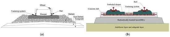
Figure 1. Schematic view of (a) ballasted track; (b) concrete slab track (reproduced from [5]).
In recent decades, ultra-high-speed and heavier-haul railways have been developed in many countries (such as China, France and Japan) [10]. The rolling stocks with higher speed and larger mass can induce dynamic axle load with greater magnitude and higher frequency than in the past, which puts forward stricter requirements on the reliability of the railway systems than before. Most recently, the railway turnout system’s safety and reliability are becoming a major problem due to the aforementioned trends. The failure and deterioration of the railway infrastructures caused by the train passing, the environmental variation, and the deterioration of ballasted layers is more frequent than before. The typical components of the railway turnout system, such as rail pads, concrete bearers and ballasted beds, were designed to support the rolling stocks with normal speed and mass. Those components may fail when subjected to the current complex load, which results in a great risk to comfort and safety. In extreme cases, it may lead to safety incidents such as derailment and roll-over. The performance of conventional railway components is limited. Also, the severe loads can result in wheel and rail wear and difficulty in track detection. Thus, it is of great significance to design components with better energy absorption and vibration reduction performance given the current railway serving load. Many researchers have phased in new technologies to improve conventional railway track systems, such as machine learning [11], additive manufacturing [12], 3D scanning [13,14], topology optimization [15], etc.
Additive manufacturing technology, well known as 3D printing, is based on digital model files using layer-by-layer addition of metal powders or plastic materials to fabricate three-dimensional objects [16,17]. According to ASTM Standard F2792 [18], the 3D printing technologies can be classified by the processing similarities into seven groups: binder jetting, directed energy deposition, material extrusion, material jetting, powder bed fusion, sheet lamination and vat photopolymerization. Their main principles are layered manufacturing and layered overlaying. As a product of the fusion of machinery, materials, computer science and other technologies, additive manufacturing technology has made direct manufacturing driven by digital models a reality and has become a landmark technology for the new industrial revolution [19,20]. Compared with traditional manufacturing technology, 3D printing enables the integration of complex structures and mould-free manufacturing, personalized customization, multi-components and multi-materials, while reducing material waste [21]. As reported in [22], 3D printing technologies have been widely used in many fields including industrial machines, consumer products/electronics, aerospace, medical/dental, academic, government/military, architectural and etc. Figure 2 presents the proportions of 3D printing technologies adopted in different fields. The government and academic institutions have shown growing interest in 3D printing technologies for the ability to produce complex objects and the increasing 3D printing market all over the world [23]. In the last few decades, many railway institutions and researchers started to combine railway industry with 3D printing technologies. For example, Germany Siemens Mobility has established the Alliance for Availability system and plan to 3D print spare parts for railway vehicles; Mobility Goes Additive (MGA) has printed the first safety component for the railway sectors; the China Academy of Railway Sciences (CARS) established the 3D printing lab in 2016 for phasing 3D printing into track structures.
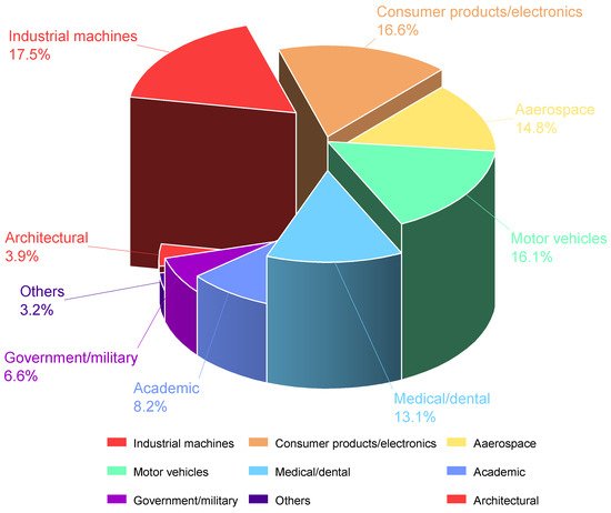
Figure 2. Industrial usage of 3D printing technologies.
2. Additive Manufacturing in Railway Components
The railway track infrastructure is a complex system composed of multiple components. Each component must have sufficient strength, elasticity and durability to provide adequate lateral and longitudinal resistance and proper track stiffness. In this section, the research about each component related to additive manufacturing technology is reviewed.
2.1. Rails
The rail directly supports the rolling stock and guides the direction of passing trains. The dynamic loads induced by the moving vehicles can result in rail corrugation, wear, rolling contact fatigue (RCF) issues and surface damage [24,25,26]. With the rapid development of high-speed and heavy-haul railway lines, the risk of rail damage and failure is increasing [27,28]. In order to improve the rail wear and RCF resistance, the select laser melting(SLM) additive manufacturing technology, also called laser melting, have been adopted by many researchers to produce an enhanced layer on the rail top surfaces [29].
The European InfraStar project first used the laser cladding technology to produce a reinforced layer on the railhead area [30,31,32,33], as shown in Figure 3a. The noise measurements of the enhanced bi-material rails with different Duroc materials were then carried out in Malmbanan (Figure 3b). This approach can increase rolling contact fatigue performance, shorten the maintenance intervals and reduce the noise caused by wheel–rail interaction [30]. Compared with past repairing technology, the additive manufacturing not only can repair the local real damage but also can improve the rail performance and prolong rail service life [34].
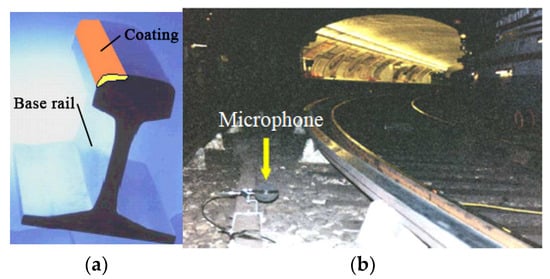
Figure 3. European InfraStar project. (a) the two-material rail; (b) noise measurements at Malmbanan. (Both reproduced from [30]).
Figure 4 shows the schematic of the laser cladding process. The laser cladding process includes: (1) a molten pool is built on the substrate (railhead) using laser beam; (2) metallic powders are delivered to the molten pool area by carrier gas; (3) the metallic powders are molten, fused with the base substrate in molten pool and cooled down; (4) the nozzles and laser beam are moved through a certain routine controlled by the computer. The processes are repeated [35,36].
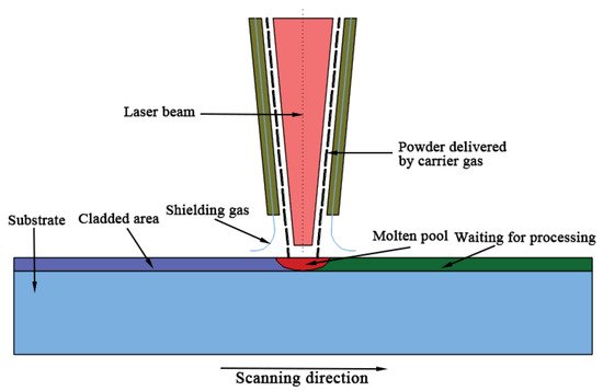
Figure 4. Schematic diagram of laser cladding process.
The mechanical properties (e.g., tensile strength and residual stress) of laser cladded rail is affected by the material type, the granularity of alloy powders and 3D printing processes (e.g., scanning pattern, designed angle, printing speed and laser power) [37,38]. The laser cladding can be used to enhance many types of rails, including hyper-eutectoid rail, U71Mn rail (GB), R400HT(EN), HE400(EN), R260(EN), R200(EN). The cladded layer can be classified into Fe-based, Ni-based, Co-based and other types according to the base material type. The summary of cladding materials for enhancing rails and the related 3D printing process are listed in Table 1. The influence of laser cladding on the rail has not been fully understood. However, it can be concluded from the present research that: (1) increasing laser power can help create fine cladding grain [39,40]. (2)The size of cladded layer is significantly affected by the powder feeding speed [41,42]. (3) The grain size and morphology of the cladding layer are determined by the thermal history [38,43]. The high G/R, the ratio of temperature gradient at the solid-liquid interface (G) to thermal gradient cooling rate(R), can promote the occurrence of columnar crystal [24]. The low G/R can help the generation of dendrite crystal [44,45,46]. (4) Angular microstructures can provide higher hardness than the leaf-like microstructures [47]. (5) Laser cladding can increase the hardness of rail. The hardness increases to the max at around 0.25 mm along the depth direction in the cladded layer and then decreases to the same as the substrate rail [48]. (6) The hardness of cladded rail is not sensitive to small changes in laser cladding processes [49]. (7) The higher content of MxCy phases and martensitic structure can make the rail cladded layer harder [50]. (8) Increasing the hardness of rail can prevent wear and crack occurrence on the rail-wheel interface [51,52]. (9) The thermal processing(heating and cooling) in laser cladding can produce residual stress inside the rail, which will damage rail fatigue and anti-cracking performance [53,54,55]. (10) Post-heat treatment to the cladding layer can improve ductility and elongation [56]. (11) The bending strength of the cladding layer is better than the substrate rail [28], and the formation of fine pearlite microstructures can benefit the bending behaviour [50,57]. (12) The fatigue performance of cladding layers is determined by the properties of the heat affected zone. The laser cladded layer has a uniform deformation when exposed to dynamic load, which can restrain the crack and rail surface failure [48,58,59,60]. (13) Adding reinforcement materials into the cladding layer can help improve the mechanical properties of the rail [61]. (14) Optimization of additive manufacturing processes, such as a magnetic approach, WAAM and HF-WAAM, can help improve the yield strength and ultimate tensile strength of rails [62,63,64,65].
Table 1. Materials used in laser cladding repaired and enhanced rail.
| Reference | Base Material of Powders | Powder Type |
|---|---|---|
| Lai et al. (2019) [40] | Fe-based | 410L, 420SS |
| Co-based | Stellite 6, Stellite 21 | |
| Lu et al. (2019) [66] | Fe-based | martensitic stainless steel (MSS) |
| Roy et al. (2018–2020) [55,56,57,58,59,60,61,62,63,64,65,66,67] | Fe-based | 410L, 420SS |
| Co-based | Stellite 6 | |
| Fu et al. (2015) [43] | Fe-based | martensitic stainless steel (MSS) |
| Zhu et al. (2019) [68] | Fe-based | 316L, 410L, 420L |
| Lewis et al. (2015–2017) [52,69,70] | Fe-based | Hadfield, martensitic stainless steel (MSS), 316 Stainless |
| Co-based | Stellite 6 | |
| Narayanan et al. (2019) [71] | Fe-based | a premium martensitic stainless steel |
| Meng et al. (2019) [50,57] | Ni-based | Not mentioned |
| Wang et al. (2017–2018) [35,36,53] | Fe-based | AISI316L stainless steel produced by Höganäs |
| Seo et al. (2019) [12] | Co-based | Stellite 21 |
| Ni-based | Inconel 625, Hastelloy C | |
| Clare et al. (2012) [47] | Ni-based | Stellite 6 |
| Guo et al. (2015) [24] | Co-based | Not mentioned |
| Wang et al. (2014) [48] | Co-based | Not mentioned |
| Aladesanmi et al. (2019) [72] | Others | Ti, TiB2 |
Ref. [73] adopted the fused deposition modelling method to fabricate composite rails for micro-people movers (MPM) and evaluated the failure modes of the printed rails with different polylactide fibre contents (material density) under static load tests. The size of the printed rail and the test settings are present in Figure 5. The results indicate that the bearing capacity of the 3D printed rails is determined by the fibre contents and the printing direction, and the failure modes change from material-control to structure-control as the fibre contents increase from 20% to 100%.
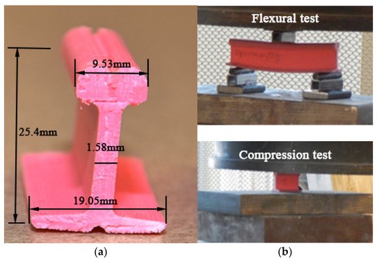
Figure 5. Prototyping rail for micro-people movers using additive manufacturing: (a) 3D printed composite rail; (b) compression and flexural tests. Both have been reproduced from [73].
2.2. Fasteners
The railway fastener system helps to fix rails on sleepers or track slabs and provides elasticity for the rails [74,75]. There are many types of fastener system all over the world, such as 102 and 8 K types from Japan, Nabla from French [76], RST and VOSSLOH 300 from German [77,78], Pandrol series from the UK [79] and WJ series from China [80]. Their components and structures are different, but they can be regarded as comprising three parts: withholding parts (e.g., clips, clamps), jointing parts (e.g., dog spikes, screw spikes and dowels) and elastic pads (rail pads). The railway fastener systems develop from simple shapes to complex structures, as shown in Figure 6. The fastener systems can be classified into rigid type (Dog spike and KPO type) and elastic type (Shrapnel type and Spring type). The elastic fasteners provide greater elasticity, better fatigue performance and higher corrosion resistance than rigid type fasteners and have become the most widely used fastener systems in current railway lines.
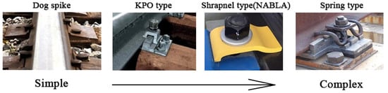
Figure 6. The change of railway fastener systems.
However, it is easy for the fastener systems to fail or be damaged under long-term railway dynamic loads, especially on high-speed and heavy-haul railway lines. In order to design a new type of railway fastener, the CARS in China has adopted 3D printing technology to produce sand-casting moulds for helping fabricate steel fastener plates [81], as present in Figure 7a. Compared with traditional methods, the 3D printing process had shortened the manufacturing time to about 25 days and decreased the cost. Moreover, the 3D printing sand-casting moulds can help the cooling process by the embedded water cooling path, as shown in Figure 7b. The water-cooling path was designed to follow the fastener clip shape, which can make the cooling more effective and reduce the sample deformation. This approach can reduce the moulding time from 150–190 s to 124.5 s. CARS also used the 3D printing technology to optimize the geometry shape of the clip and the crews of the railway fastener system, as shown in Figure 8a,b [81]. The design can decrease material usage, increase elasticity by a special shape, and increase mechanical strength and chemical resistance by combining high-performance materials. Also, reference [82] tested the reinforcing effects of 3D printed bolts on rocks.
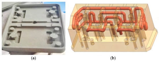
Figure 7. Three-dimensional printed sand-casting moulds: (a) 3D printed moulds for fastener steel plate; (b) schematic smart moulds with embed complex cooling path. Retrieved from [81].
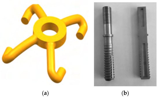
Figure 8. Optimization of railway fastener clip and screw: (a) schematic clip with shape optimization; (b) 3D printed optimized screws. Retrieved from [81].
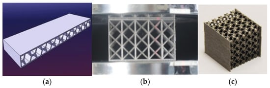
Rail pads in fastener systems provide the most elasticity and can reduce the magnitude of the wheel–rail contact force [83,84]. The dynamic performance of railway fastener systems is affected by the pad material, thickness and geometric shape [85]. Thus, the 3D printing technology can be used to produce elastic pads with enough strength and stiffness for railway fastener systems. There is no report directly related to 3D printed rail pads, but similar research in 3D printed elastic pads has been investigated in aerospace members and civil engineering fields. For example, the cellular honeycomb structures have high specific strength and energy absorption capacity [86]. The stiffness of the honeycomb structure can be designed by a given thickness [87,88,89], which can match different railway line requirements. These honeycomb structures have already been adopted in fabricating aeroplanes to replace conventional metallic components for noise reduction, impact load reduction and thermal control [90,91]. Lattice structures are also a prospecting structure for rail pads. The lattice structures have good vibration properties [92,93,94], high indentation resistance and greater mechanical strength and stiffness when exposed to bending moments and compressive loads [95]. Moreover, by structural design, the lattice structures can gain a negative Poisson’s ratio [96]. Triply periodic minimal surface (TPMS) structures are newly developed porous structures inspired by natural creatures [97,98]. Those TPMS structures have higher specific strength and stiffness compared to common lattice and honeycomb structures [99]. Examples of honeycomb structures, lattice structures and TPMS structures are present in Figure 9. These structures have the potential to be used as elastic sandwich layers in rail pads for their designable stiffness and high specific strength.
2.3. Sleepers
Sleepers support the rail and redistribute the loads to the ballasted layer. The sleepers can be classified into timber, concrete and steel sleepers according to the materials. Concrete sleepers have been widely adopted for their vast resources, good elasticity, long life cycle and good chemical resistance [102]. The optimization of present sleepers is conducted from the material aspects. For example, by adding fibres and rubber particles into composite and concrete sleepers, the mechanical performance of sleepers can be improved. Composite sleepers were newly developed in the 1980s, and the base materials include glass fibre, polyurethane, rubber and resin [103,104]. Because the materials are recyclable and have good elasticity and insulation, the market share of composite sleepers is increasing year by year. The shift2rail project has tried using 3D printing technology to produce a composite bearer with multi-layers [105], as shown in Figure 10. Layer 1 should exceed 150 mm to provide enough stiffness and space for installing fastener systems. layer 3 (soft layer) works as an under-sleeper pad; its depth should exceed 10 mm for 63 mm ballast, 8 mm for 53 mm ballast and 6 mm for ballast less than 53 mm. The depth of layer 2 is determined by the balance of the total depth of bears, layer 1 and layer 3. The required Young’s modulus and density for Layer 1, 2 and 3 decreases as the depth increases.
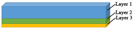
Figure 10. Three-dimensional (3D)-printed composite bearers with multi-layers.
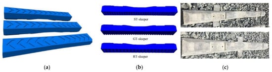
For timber sleepers and concrete sleepers, no research related to additive manufacturing technologies has been conducted. Some researchers have conducted shape optimisation of the sleepers, such as sleepers with arrowhead grooves [106], sleepers with bottom textures [107] and winged sleepers [108,109], as shown in Figure 11. The sleeper can distribute loads more evenly by optimising the geometric shape and providing better lateral and longitudinal resistance [107,108]. It should be noted that producing sleepers with complex shapes using a traditional moulding method is difficult; prototype sleepers with complex shapes for research purposes can be fabricated easily using 3D printing process.
2.4. Supporting Layers
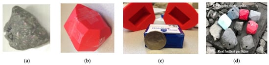
Ballasted beds are the assembly of crushed rock particles with specific particle size distribution, which differs according to the designed railway line conditions. The ballast particles move, rotate and interact with each other under dynamic train loads and then deteriorate. The maintenance of a ballasted track is important for keeping ballasted track with enough stiffness and elasticity. One difficulty of ballasted tracks is to detect the ballasted bed conditions. Because the ballasted bed is composed of small discrete particles with a porosity of 0.2–0.4, it is hard to evaluate the mechanical behaviour of the ballasted layer and access the dynamic reactions of ballast particles. References [110,111,112,113] used 3D printing technology to fabricate several smart ballast rocks to record ballast particle movement (e.g., acceleration and rotation) in field tests. The geometric shapes of smart rocks were obtained by mimicking an actual ballast particle shape, and the removable sensor was installed in the 3D printed rock, as shown in Figure 12. Also, ref. [114] adopted similar SmartRocks to evaluate the ballast condition. Reference [115] 3D printed ballast particles with/without predefined fissure using photosensitive resin material and gypsum powder. Their time-dependent behaviours were compared with limestone ballast particles. The 3D scanning approach was adopted to obtain the geometric shape of real limestone ballast particles. References [116,117] tried using 3D printing technology to fabricate the sample with similar mechanical behaviour to real rocks. The results indicate that 3D printed samples have good mechanical behaviour, but the 3D printing technology still needs to be improved [116,117,118,119].
A number of railway track slabs, including sleepers on slab systems, embedded sleeper systems and direct systems, have been developed in the past few decades [5]. Most ballast-less track slabs are fabricated from concrete, CA mortar fillings and steel tendons. Many railway companies (e.g., SATEBA in Europe and Stabirail in Belgium) have been developed advanced railway track slabs with optimized geometry for high-speed and heavy-haul railway lines; 3D printing concrete technologies have already been adopted in bridges, civil buildings and art architectures [121,122], which strengthens the railway industry’s desire for 3D printed concrete infrastructures. The British HS2 claimed to launch the ‘Printfra-structure’ project in 2022, which will 3D print concrete slab onsite [123]. The concrete materials will be enhanced with graphene for replacing steel tendons. This approach can decrease carbon emission and concrete usage [123].
2.5. Special Components
Railway track infrastructure includes some special components for addressing particular issues on sites, such as geogrids and geocells for increasing ballast interaction, retaining walls for constraining ballast movement, sound barriers for noise reduction, and sand guard walls for blocking sands. The 3D printing technologies have been utilized in geogrids, geocells and sound barriers.
A geogrid and geocells are used to increase the cohesion of granular materials. Reference [124] 3D printed two types of 1:10 mode geogrids, as shown in Figure 13a. The 3D-printed models have lower yielding strain (5% to 6%) than full-scale geogrids (10%), which indicates the printed geogrids need to be enhanced. Reference [125] printed a bio-inspired honeycomb geogrid for soil reinforcement, as shown in Figure 13b. Ref. [126] 3D printed geocells, as shown in Figure 13c, and optimized the integral node shape. Reference [127] printed a smart geogrid, as shown in Figure 13d. The geogrid is equipped with fibre Bragg grating, which enables real-time accurate strain detection. Reference [128] printed a three-dimensional geogrid, as shown in Figure 13e, and tested the shearing performance. These applications can also be used in ballast layers for increasing the ballast biting effects.
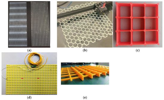
Figure 13. Three-dimensional printed geogrids and geocells: (a) 3D printed 1:10 model geogrids from [124]; (b) a 3D printed bio-inspired honeycomb geogrid from [125]; (c) a 3D printed geocell from [126]; (d) a 3D printed smart geogrid from [127]; (e) a 3D printed three-dimensional geogrid from [128].
With the development of ultra-high-speed and heavy-haul railway lines, noise has become much more severe and affects the normal life of residents near the railway lines [129]. Sound barriers are a solution for reducing the noise caused by moving railway trains [130,131]. By optimizing the barrier shape, the noise reduction effect can be improved. The 3D printing technology can help produce sound barriers with complex geometric properties. A low-height noise barrier for railway systems was reported in [132]. The size of the unit cell is present in Figure 14a. The unit can be printed in factories and assembled on site. The approach can reduce more than 50% carbon emission [132]. Reference [133] designed a 3D printable ultrathin low-frequency sound absorbing panel, as shown in Figure 14b. Reference [134] designed, 3D printed two types of sound barriers with coiled and rigid unit cells, as shown in Figure 14c, and tested the noise reduction performance. As for 3D printed concrete noise barriers, several acoustic walls, as shown in Figure 14d–f, were built by WINSUN Ltd. in Suzhou, China. These noise barriers can reduce noise by a total of 30 decibels. The 3D printing sound barrier technology is well-developed for adoption in railway noise barriers.
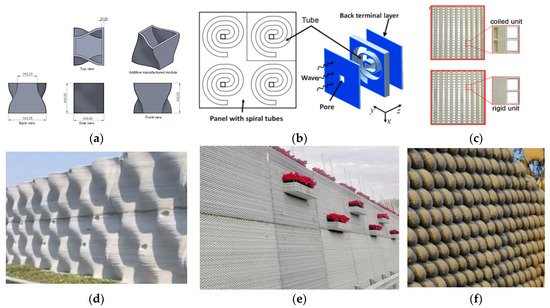
Figure 14. Three-dimensional printed sound barriers: (a) a low-height noise barrier for railway system (concept by Design Reform Ltd., 2020), from [132]; (b) unit cell of the ultrathin low-frequency sound absorbing panel from [133]; (c) two 3D printed acoustic barrier samples, from [134]; (d–f) 3D printed acoustic walls in Suzhou, China.
This entry is adapted from the peer-reviewed paper 10.3390/jcs6010007
This entry is offline, you can click here to edit this entry!