Your browser does not fully support modern features. Please upgrade for a smoother experience.
Please note this is an old version of this entry, which may differ significantly from the current revision.
Subjects:
Engineering, Aerospace
Robust finite element models are utilised for their ability to predict simple to complex mechanical behaviour under certain conditions at a very low cost compared to experimental studies, as this reduces the need for physical prototypes while allowing for the optimisation of components.
- crashworthiness
- composites
- FEA
- LS-DYNA
1. Introduction
Two classes of finite element methods are available: either the implicit or explicit method [1]. The implicit method is widely available and used in a broad range of problems, including nonlinear stress analysis and static. The explicit method is widely used in highly nonlinear stress analysis and dynamics with contact-dominated problems. A car crash, for instance, or metal stamping simulations are applications well suited for the explicit method.
Due to the high cost of conducting experimental studies, there is a need for reliable computational models capable of predicting the crushing response of composite structures. There have been various attempts to develop explicit finite element models (FEMs), with different degrees of precision, for circular tubes [2,3,4,5,6], square tubes [4,5,6,7,8,9,10,11,12,13], angle-stiffeners [8], C-channels [8] and hat-stiffeners [14]. The classification of structural FEM can be divided into two groups. The first group is the micro-mechanical one [15,16,17,18,19,20]. In this group, the finite element models try to simulate the composite crushing phenomenon through a detailed modelling of its micromechanical behaviour. A very fine solid mesh is developed to accurately capture the micro-mechanics matrix crack propagation phenomenon. The computational effort demanded by this kind of model is very high, which makes it unpractical for engineering crash analysis. This approach is used mainly to perform simulations concerning the delamination phenomenon, in which the growth behaviour of a single crack is studied in a very detailed way [7]. The second group is the macro-mechanical one [3]. This type of model provides a macro-mechanical description of the material collapse. It is much more computationally effective, and consequently, it is a suitable choice for engineering crash analysis. However, it is not capable of precisely modelling all the main collapse modes that occur simultaneously during a crush event.
The FE modelling of composite structures can be either shell or solid elements. Solid element models require more computation time and are less widely used compared with shell elements used in the axial crushing of composite structures as mentioned above. A single layer [17,21,22,23,24] or multiple layers [3,25] of shell elements can be used to model a laminate. In the single-layer model, this can be modelled as a single layer of shell elements, with each ply being represented by the thickness integration point, also referred to as the integration point in the thickness direction. This kind of model is not capable of modelling the interlaminar collapse modes shown by composites under crushing in an accurate way. However, it is useful if a detailed representation of the failure physics is not required and only load and energy level predictions are required. The main advantages are its simplicity and computational effectiveness, so for that point, they are highly suitable for practical engineering crash analysis. On the other hand, they have a notably lower level of robustness due to the large amount of parameter calibration required to obtain acceptable global results for a given test configuration [7].
2. LS-DYNA Software
A commonly used piece of software for crashworthiness application by industry and academics is LS-DYNA, which was developed by LSTC and is suited for highly nonlinear transient dynamic finite element analysis.
LS-DYNA, within the past decade, has added many new features such as new material types, contact algorithms, element formulation, etc. LSTC has gradually expanded to develop a universal tool for most implicit and most vastly used explicit coding for aerospace, automotive, military and construction. LS-DYNA has its own pre-processor called LS-PrePost.
3. Simulation Setup
For the simulations, an Explicit FE LS-DYNA code is used with a multi-layered shell configuration to reduce numerical costs. Composite tubes were modelled as multi-layers of Belytschko–Tsay circular shell elements with one integration point in the element plane to represent the direction of the stacking sequence. In double-shell configuration, the GFRP innermost shell has six integration points, with another six integration points being assigned to the outermost shell to represent all twelve UD layers. In a GFRP tube, each individual layer has a thickness of 0.25 mm. The total thickness of both shells is 3 mm. Each fibre orientation is assigned with insertion of an integration point with respect to the stacking sequence used with its associated thickness. The material properties are obtained from [56,59,60].
4. Finite Element Modelling
4.1. Delamination Interface
Many researchers have used friction to simulate delamination, e.g., [56,57,58,59,60]. Friction influences the energy absorption capability; however, using friction influences the SEA value, increases friction between the shells, and causes a higher SEA value (see Section 5.3), and this compared with experimental data cannot be considered as a correct FEM. Due to this, a different approach was considered. Tiebreak option 8 was utilised instead of friction to model delamination as this contact card can define the Mode-I and Mode-II energy release rate, which simulates delamination.
The tiebreak contact definition implemented in LS-DYNA allows for the simulation of delamination at the interface between adjacent shell element layers. Tiebreak Option 8 formulations were investigated for this study, namely, tiebreaks with a bilinear traction-separation law. This requires interlaminar normal and shear strengths and a critical distance to interface failure as input parameters to model delamination in crush simulations [10]. However, the optimal critical failure distance parameter selection has not been thoroughly studied in the open literature. The formulation of required input parameters, such as interlaminar normal and shear strengths, fracture toughness under pure Mode-I and Mode-II loading, and interfacial stiffness for normal and shear modes; a description of the model setup using each formulation is explained in Section 4.3.1. To determine the energy rate of Mode-I and Mode-II, DCB and 3ENF tests were carried out.
4.2. Boundary Conditions and Contact Definitions
The loading striker was modelled as a rigid body. The tubes were placed in the Z-direction upright and the loading striker at the chamfered end of the tube. The interaction between the loading striker and the tube was modelled using a node-to-surface contact definition (automatic contact from node to surface). The tiebreak contact definition between the shell layers not only facilitates the simulation of delamination but also prevents layers from penetrating each other after the tiebreak has failed, as the contact definition would remain in effect. In summary, Automatic_Node_To_Surface contact was defined for the striker and inner shell with striker being the master and inner shell being the slave. The Automatic_Single_Surface contact algorithm was utilised. This prevents penetration of the crushing tube by its own nodes, which is due to the sticker’s nodes potentially causing disturbance to the model and the inner shell penetrating its own nodes and elements. All bottommost nodes of all shell element layers are constrained in their translational degrees of freedom.
5. Model Sensitivity to Physical Parameters
A robust finite element model needs to tolerate small variations in modelling parameters and be able to capture the differences.
5.1. Material Model
The following parameters from Mat_54-55 in LS-DYNA have been studied: stiffness, compressive strength, strain to failure in compression and strain to failure in tension. The stiffness and strength have an influence on fibre and matrix arrangements, and the strain to failure is a parameter that influences the experimental energy absorbed per unit of crushed volume/mass. The developed model will be compared with the experimental data. The SEA value from the experimental and numerical data should be around the error percentage, which is 5%.
5.3. Friction
The coefficient of friction is one of the physical parameters that influences the progression of the simulation. In the literature, many values have been stated, varying from 0.1 to 0.3 for static and 0.1 to 0.2 for dynamic. The chosen values for static friction coefficient is 0.3 and 0.2 for the dynamic friction coefficient [3,4,5,6,7,43,53,59,60]. Both impactor to inner shell and inner shell to outer shell friction coefficients are set to 0.3 and 0.2 for static and dynamic, respectively. This is based on trial and error and based on previous researchers [3,4,5,6,7,43,53,59,60]. This combination enables a sensitive crushing performance.
5.4. Impact Velocity
Understanding how the model is robust with respect to the input kinetic energy would indicate the range of impact conditions predicted by the model.
Figure 22 shows the extracted results from the simulations. The simulation results illustrate a similar value or up to 0.4% difference in initial peak value, and the specific energy absorption, which indicates the energy absorption per crushed mass, is within 4% of the reference model. The mean crushing force is slightly affected, although the highest difference from the reference model is 3.5%.
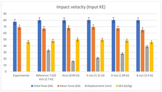
Figure 22. Impact velocity or kinetic energy input sensitivity data [66].
6. Conclusions
Various shell configurations were studied, and a multi-layer shell element with double-shell configuration produced accurate enough results with a difference of less than 5% with minimal computational costs compared with other configurations. This configuration was used to predict energy absorption capability and specific energy abortion, and other considerations were deformation and damage progression of the composite tubes. Each shell element or layer can contain either a single ply or multiple plies. The layers were tied using tiebreak option 8 contact definitions. This contact card has the capability of modelling delamination between the layers through an energy-based approach. The material card of Mat_54 was used to represent each ply, and a few parameters in the material cards were studied to find the optimum configurations to match the experimental studies. SOFT and DFAILC (compression failure strain) were the main parameters that affected the energy absorption capability, and specific energy absorption was influenced by these parameters. The sensitivity of the model was studied against the material model, delamination model, friction and impact velocity. The results show that the model is sensitive towards minimal input change. The simulation results showed that the failure peak load, mean crushing force, and SEA all compared very well with the experimental results.
This entry is adapted from the peer-reviewed paper 10.3390/jcs6010011
This entry is offline, you can click here to edit this entry!