Machines with more than three phases are called multiphase machines, which provide a better current distribution among phases, and lower current harmonic production in the power converter, than conventional three-phase machines. However, multiphase drive applications require the development of complex controllers to regulate the torque (or speed) and flux of the machine. In this regard, direct torque controllers have appeared as a viable alternative due to their easy formulation and high flexibility to incorporate control objectives.
- direct torque control
- multiphase
- electrical drives
1. Introduction
Electric drives are the basis of locomotive traction, electric ship propulsion, electric aircraft with various auxiliary functions (e.g., fuel pumps, starter/generator solutions, etc.), and renewable energy production. Although conventional three-phase drives represent the principal choice for industrial applications, multiphase ones have recently aroused the interest of practitioner engineers and researchers in the field. Any energy conversion system formed by a multiphase electric machine and converter and regulated by a certain control technique is called a multiphase drive. The first application of such a system, particularly for a five-phase drive, was used in the late 1960s [1], showing the advantages of multiphase systems over conventional three-phase ones. The main interest in the proposal was that the higher number of phases yields a torque ripple three times lower with respect to the equivalent three-phase case due to a better power distribution per phase, this being one of the most reported problems in conventional drives at that time. However, it was not until the end of the 20th and the beginning of the 21st centuries that the interest of researchers in multiphase machines was renewed due to two main reasons. First, the development of high-power and high-frequency semiconductors and, consequently, the appearance of pulse width modulation (PWM) methods to control the ON and OFF states of these electronic devices, as well as the energy conversion process. Second, there is the development of microelectronic technology and the appearance of powerful electronic devices with the ability to implement control algorithms in real time, such as digital signal processors (DSPs) and field-programmable gate arrays (FPGAs).
-
The fault-tolerant capability against a fault situation in the machine and/or the power converter, first presented in [2]. An n-phase machine can operate after one or several fault occurrences without any external equipment, as long as the number of healthy phases remains greater than or equal to three (assuming a single isolated neutral connection). Consequently, the system reliability is enhanced at the expense of a reduction in the post-fault electrical torque production.
-
The capability of increasing the power density in healthy operation by injecting specific current harmonics, exposed in [3]. This is possible in certain multiphase machine configurations based on concentrated windings, where the lower current harmonic components can be used to increase the torque production.
Although field-oriented control (FOC) methods, based on decoupled control of the flux and electromagnetic torque and assisted by modulation stages, can be considered as the most popular control technique for conventional and multiphase drives [4][5], direct control techniques have recently been presented as interesting competitors [6][7][8]. The essence of direct controllers is to eliminate any form of modulation, forcing the states of the power switches to rapidly track a reference value. Then, the meaning of ‘direct control’ techniques is related to control strategies without the intervention of a pulse width modulation or any other form of modulation, providing control commands that are applied directly to the power converter. As a main consequence, direct controllers, being direct torque controllers (DTC) are the most extended industrial alternative, can favor fast torque responses and control robustness with respect to the variation of the electrical parameters of the machine. In this regard, DTC appears to be a viable (from a commercial perspective) control alternative in conventional three-phase drives due to an easy formulation and high flexibility to incorporate different control objectives. However, the use of DTC in multiphase drives is restricted in normal operation due to the impossibility of regulating more than two degrees of freedom (electrical torque and stator flux).
2. Five-Phase Distributed Windings Induction Motor Drive Using a Conventional Two-Level VSI
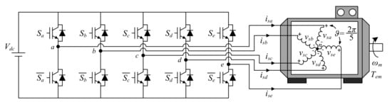
A graphical representation of the analyzed system is shown in Figure 1. It is based on a five-phase Induction Machine (IM) with a squirrel-cage rotor and symmetrically distributed stator windings (spatial equal displacement between windings) fed by a DC power supply through a five-phase two-level voltage source inverter (VSI).
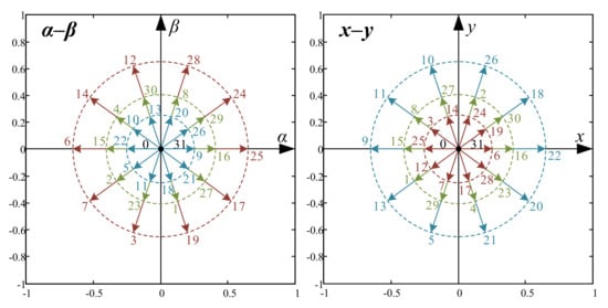
3. DTC in Five-Phase Drives
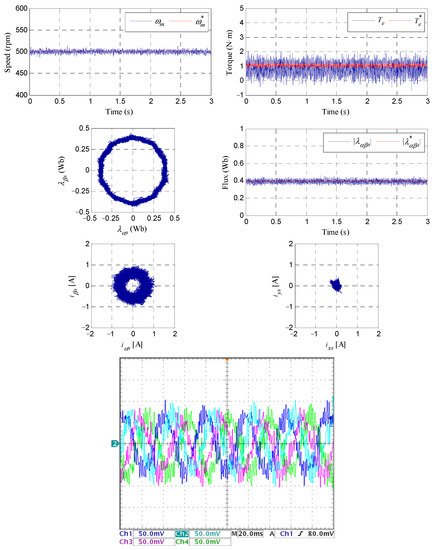
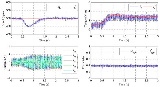
4.1. Steady-State Operation
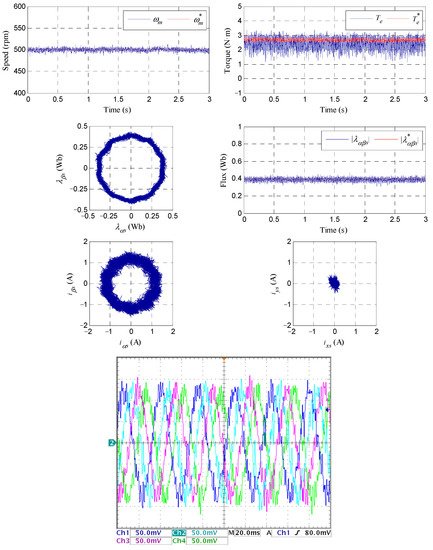
4.2. Load Torque Rejection
This entry is adapted from the peer-reviewed paper 10.3390/app112411964
References
- Warg, E.E.; Härer, H. Preliminary investigation of an inventor-fed 5-phase induction motor. Proc. Inst. Electr. Eng. 1969, 116, 980–984.
- Jahns, T.M. Improved reliability in solid-state AC drives by means of multiple independent phase drive units. IEEE Trans. Ind. Appl. 1980, IA-16, 321–331.
- Toliyat, H.A.; Lipo, T.A.; White, J.C. Analysis of a concentrated winding induction machine for adjustable speed drive applications. I. Motor analysis. IEEE Trans. Energy Convers. 1991, 6, 679–683.
- Barrero, F.; Duran, M.J. Recent advances in the design, modeling, and control of multiphase machines—Part I. IEEE Trans. Ind. Electron. 2016, 63, 449–458.
- Duran, M.J.; Barrero, F. Recent advances in the design, modeling, and control of multiphase machines—Part II. IEEE Trans. Ind. Electron. 2016, 63, 459–468.
- Bermúdez, M.; Martín, C.; González, I.; Duran, M.J.; Arahal, M.R.; Barrero, F. Predictive current control in electrical drives: An illustrated review with case examples using a five-phase induction motor drive with distributed windings. IET Electr. Power Appl. 2020, 14, 1291–1310.
- Arahal, M.R.; Martin, C.; Barrero, F.; Duran, M.J. Assessing variable sampling time controllers for five-phase induction motor drives. IEEE Trans. Ind. Electron. 2020, 67, 2523–2531.
- Arahal, M.R.; Satué, M.G.; Barrero, F.; Ortega, M.G. Adaptive Cost Function FCSMPC for 6-Phase IMs. Energies 2021, 14, 5222.
- Takahashi, I.; Noguchi, T. A New Quick-Response and High-Efficiency Control Strategy of an Induction Motor. IEEE Trans. Ind. Appl. 1986, IA-22, 820–827.
- Depenbrock, M. Direct self-control (DSC) of inverter-fed induction machine. IEEE Trans. Power Electron. 1988, 3, 420–429.
- Fei, Y.; Xiaofeng, Z.; Minzhong, Q.; Chengdong, D. The direct torque control of multiphase permanent magnet synchronous motor based on low harmonic space vector PWM. In Proceedings of the IEEE International Conference on Industrial Technology (ICIT-2008), Chengdu, China, 21–24 April 2008; pp. 1–5.
- ABB Group. DTC: A Motor Control Technique for All Seasons. ABB White Paper. 2015. Available online: http://library.e.abb.com/public/0e07ab6a2de30809c1257e2d0042db5e/ABB_WhitePaper_DTC_A4_20150414.pdf (accessed on 27 October 2021).
- Hadiouche, D.; Razik, H.; Rezzoug, A. On the modeling and design of dual-stator windings to minimize circulating harmonic currents for VSI fed AC machines. IEEE Trans. Ind. Appl. 2004, 40, 506–515.
- Buja, G.S.; Kazmierkowski, M.P. Direct torque control of PWM inverter-fed AC motors—A survey. IEEE Trans. Ind. Electron. 2004, 51, 744–757.
- Kianinezhad, R.; Nahid, B.; Betin, F.; Capolino, G.A. A novel Direct Torque Control (DTC) method for dual three phase induction motors. In Proceedings of the IEEE International Conference on Industrial Technology (ICIT 2006), Mumbai, India, 15–17 December 2006; pp. 939–943.
- Kianinezhad, R.; Alcharea, R.; Nahid, B.; Betin, F.; Capolino, G.A. A novel direct torque control (DTC) for six-phase induction motors with common neutrals. In Proceedings of the International Symposium on Power Electronics, Electrical Drives, Automation and Motion (SPEEDAM 2008), Ischia, Italy, 11–13 June 2008; pp. 107–112.
- Zheng, L.; Fletcher, J.E.; Williams, B.W.; He, X. A Novel Direct Torque Control Scheme for a Sensorless Five-Phase Induction Motor Drive. IEEE Trans. Ind. Electron. 2011, 58, 503–513.
- Parsa, L.; Toliyat, H.A. Sensorless Direct Torque Control of Five-Phase Interior Permanent-Magnet Motor Drives. IEEE Trans. Ind. Appl. 2007, 43, 952–959.
- Gao, Y.; Parsa, L. Modified Direct Torque Control of Five-Phase Permanent Magnet Synchronous Motor Drives. In Proceedings of the 22nd Annual IEEE Applied Power Electronics Conference and Exposition (APEC 2007), Anaheim, CA, USA, 25 February–1 March 2007; pp. 1428–1433.
- Gao, L.; Fletcher, J.E.; Zheng, L. Low-Speed Control Improvements for a Two-Level Five-Phase Inverter-Fed Induction Machine Using Classic Direct Torque Control. IEEE Trans. Ind. Electron. 2011, 58, 2744–2754.
- Riveros, J.A.; Duran, M.J.; Barrero, F.; Toral, S. Direct torque control for five-phase induction motor drives with reduced common-mode voltage. In Proceedings of the 38th Annual Conference on IEEE Industrial Electronics Society (IECON 2012), Montreal, QC, Canada, 25–28 October 2012; pp. 3616–3621.
- Tatte, Y.N.; Aware, M.V. Direct Torque Control of Five-Phase Induction Motor with Common-Mode Voltage and Current Harmonics Reduction. IEEE Trans. Power Electron. 2017, 32, 8644–8654.
- Chikondra, B.; Muduli, U.R.; Behera, R.K. An Improved Open-Phase Fault-Tolerant DTC Technique for Five-Phase Induction Motor Drive Based on Virtual Vectors Assessment. IEEE Trans. Ind. Electron. 2021, 68, 4598–4609.
- Barrero, F.; Bermúdez, M.; Durán, M.J.; Salas, P.; González-Prieto, I. Assessment of a Universal Reconfiguration-less Control Approach in Open-Phase Fault Operation for Multiphase Drives. Energies 2019, 12, 4698.