The growing demand and diversity in the application of industrial composites and the current inability of present non-destructive evaluation (NDE) methods to perform detailed inspection of these composites has motivated this comprehensive review of sensing technologies. NDE has the potential to be a versatile tool for maintaining composite structures deployed in hazardous and inaccessible areas, such as offshore wind farms and nuclear power plants. Therefore, the future composite solutions need to take into consideration the niche requirements of these high-value/critical applications. Composite materials are intrinsically complex due to their anisotropic and non-homogeneous characteristics. This presents a significant challenge for evaluation and the associated data analysis for NDEs. For example, the quality assurance, certification of composite structures, and early detection of the failure is complex due to the variability and tolerances involved in the composite manufacturing. Adapting existing NDE methods to detect and locate the defects at multiple length scales in the complex materials represents a significant challenge, resulting in a delayed and incorrect diagnosis of the structural health. This paper presents a comprehensive review of the NDE techniques, that includes a detailed discussion of their working principles, setup, advantages, limitations, and usage level for the structural composites. A comparison between these techniques is also presented, providing an insight into the future trends for composites’ prognostic and health management (PHM). Current research trends show the emergence of the non-contact-type NDE (including digital image correlation, infrared tomography, as well as disruptive frequency-modulated continuous wave techniques) for structural composites, and the reasons for their choice over the most popular contact-type (ultrasonic, acoustic, and piezoelectric testing) NDE methods is also discussed. The analysis of this new sensing modality for composites’ is presented within the context of the state-of-the-art and projected future requirements.
- non-destructive testing (NDT)
- prognostic and health management (PHM)
- eddy current (EC)
- shearography
- infrared thermography (IT)
- computed tomography (CT)
- ultrasonic testing (UT)
- acoustic emission (AE)
- digital image correlation (DIC)
- frequency-modulated Cont
1. State-of-the-Art Review of NDE Methods
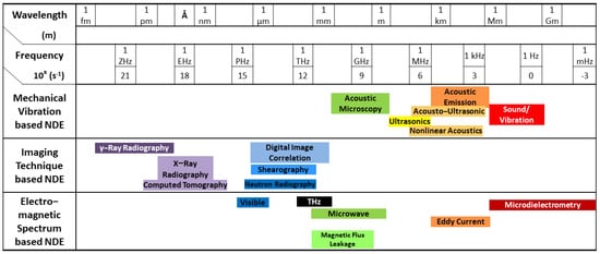
1.1. Mechanical Vibration-Based NDE
1.1.1. Electrostatic Transducer-Based Ultrasonic NDE
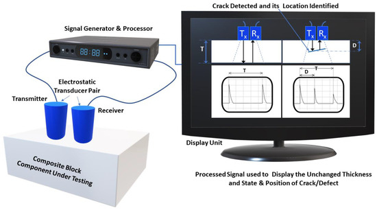
1.1.2. Piezoelectric Transducer-Based Ultrasonic NDE
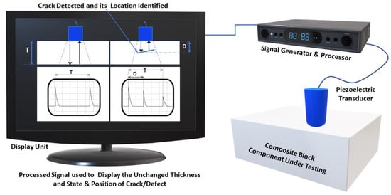
1.1.3. Acoustic Emission-Based NDE
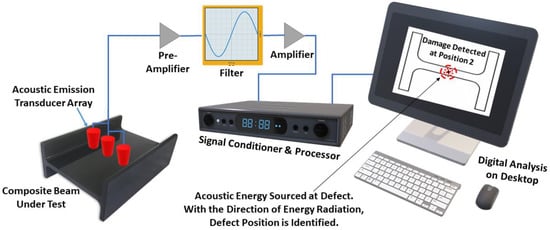
1.2. Imaging Technique-Based NDE
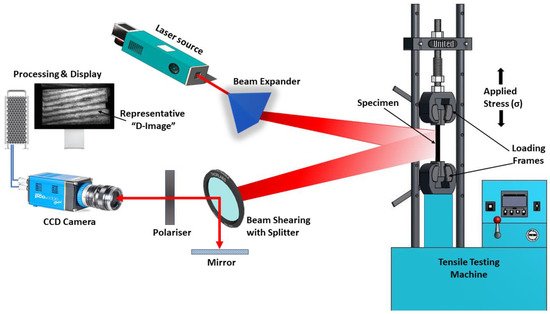
1.2.1. Shearography-Based NDE
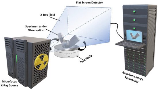
1.2.2. Computed Tomography-Based NDE
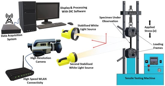
1.2.3. Digital Image Correlation-Based NDE
1.3. Electromagnetic Spectrum-Based NDE
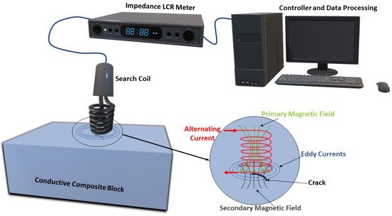
1.3.1. Eddy Current-Based NDE
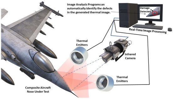
1.3.2. Infrared Thermography-Based NDE
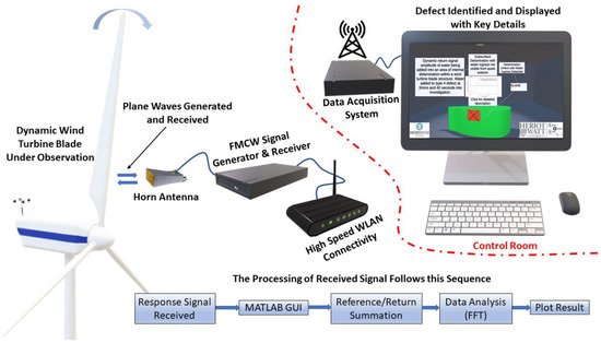
1.3.3. Frequency-Modulated Continuous Wave-Based NDE
This entry is adapted from the peer-reviewed paper 10.3390/jcs5120319
References
- Non-Destructive Testing (NDT) of Advanced Composites. Composites Design and Manufacture (Plymouth University Teaching Support Materials). Available online: https://ecm-academics.plymouth.ac.uk/jsummerscales/MATS347/MATS347A12%20NDT.htm (accessed on 10 November 2021).
- Katunin, A.; Dragan, K.; Dziendzikowski, M. Damage identification in aircraft composite structures: A case study using various non-destructive testing techniques. Compos. Struct. 2015, 127, 1–9.
- Gholizadeh, S. A review of non-destructive testing methods of composite materials. Procedia Struct. Integr. 2016, 1, 50–57.
- Stonawski, O. Non-Destructive Evaluation of Carbon/Carbon Brakes Using Air-Coupled Ultrasonic Inspection Systems; Southern Illinois University at Carbondale: Carbondale, IL, USA, 2008.
- Warnemuende, K. Amplitude Modulated Acousto-Ultrasonic Non-Destructive Testing: Damage Evaluation in Concrete; Wayne State University: Detroit, MI, USA, 2006.
- Oguma, I.; Goto, R.; Sugiura, T. Ultrasonic inspection of an internal flaw in a ferromagnetic specimen using angle beam EMATs. Prz. Elektrotechniczny 2012, 88, 78–81.
- Ducharne, B.; Guyomar, D.; Sébald, G.; Zhang, B. Modeling energy losses in power ultrasound transducers. In Power Ultrasonics; Woodhead Publishing: Sawston, UK, 2015; pp. 241–256.
- Adams, R.; Cawley, P. A review of defect types and nondestructive testing techniques for composites and bonded joints. NDT Int. 1988, 21, 208–222.
- Ramzi, R.; Mahmod, M.; Bakar, E.A. Immersion ultrasonic inspection system for small scaled composite specimen. ARPN J. Eng. Appl. Sci. 2015, 10, 17146–17150.
- Martinez, M.; Yanishevsky, M.; Rocha, B.; Groves, R.; Bellinger, N. Maintenance and monitoring of composite helicopter structures and materials. In Structural Integrity and Durability of Advanced Composites; Elsevier: Amsterdam, The Netherlands, 2015; pp. 539–578.
- Lin, L.; Luo, M.; Tian, H.; Li, X.; Guo, G. Experimental investigation on porosity of carbon fiber-reinforced composite using ultrasonic attenuation coefficient. In Proceedings of the World Conference on Nondestructive Testing, Shanghai, China, 25–28 October 2008.
- Daniel, I.; Wooh, S.; Komsky, I. Quantitative porosity characterization of composite materials by means of ultrasonic attenuation measurements. J. Nondestr. Eval. 1992, 11, 1–8.
- Collins, D.J. Damage Detection in Composite Materials Using Acoustic Emission and Self-Sensing Fibres. Doctoral Dissertation, University of Birmingham, Birmingham, UK, 2010.
- Mal, A.K.; Xu, P.; Bar-Cohen, Y. Ultrasonic NDE of Adhesive Bonds. American Society of Mechanical Engineers; American Society of Mechanical Engineers, Materials Division (Publication) MD: New York, NY, USA, 1988; pp. 85–89.
- Beall, F.C. Fundamentals of acoustic emission and acousto-ultrasonics. In Proceedings of the Sixth Nondestructive Testing of Wood Symposium, Pullman, WA, USA, 14–16 September 1987; pp. 3–28.
- Kaely, V. Ultrasonic probe velocity testing of wood. High Wycombe 1985, 3, 27.
- Hoyle, R.; Pellerin, R. Stress wave inspection of a wood structure. In Proceedings of the Fourth Symposium on Nondestructive Testing of Wood, Vancouver, WA, USA, 28–30 August 1978; pp. 33–45.
- Pellerin, R. Nondestructive Testing of Wood-A Possible Method for Timber Piling. In Proceedings of the Fourth Symposium on Nondestructive Testing of Wood, Vancouver, WA, USA, 28–30 August 1978; pp. 169–174.
- Tanasoiu, V.; Miclea, C.; Tanasoiu, C. Nondestructive testing techniques and piezoelectric ultrasonics transducers for wood and built in wooden structures. J. Optoelectron. Adv. Mater. 2002, 4, 949–957.
- McDonald, K.A. Lumber Quality Evaluation Using Ultrasonics. In Proceedings of the Fourth Symposium on Nondestructive Testing of Wood, Vancouver, WA, USA, 28–30 August 1978.
- Bradfield, G. Ultrasonic transducers: Introduction to ultrasonic transducers Part A. Ultrasonics 1970, 8, 112–123.
- Bossi, R.; Giurgiutiu, V. Nondestructive testing of damage in aerospace composites. In Polymer Composites in the Aerospace Industry; Woodhead Publishing: Sawston, UK, 2015; pp. 413–448.
- Kažys, R.; Voleišis, A.; Voleišienė, B. High temperature ultrasonic transducers. Ultragarsas Ultrasound 2008, 63, 7–17.
- Charchuk, R.; Werstiuk, C.; Evans, M.; Sjerve, E. High temperature guided wave pipe inspection. In Proceedings of the 4th International CANDU In-service Inspection Workshop and NDT in Canada 2012 Conference, Toronto, ON, Canada, 18–21 June 2012; pp. 18–21.
- Li, L.; Zhang, S.; Xu, Z.; Geng, X.; Shrout, T.R. 1-3 ceramic/polymer composites for high-temperature transducer applications. Phys. Status Solidi 2013, 210, 1888–1891.
- Arumugam, V.; Kumar, C.S.; Santulli, C.; Sarasini, F.; Stanley, A.J. A global method for the identification of failure modes in fiberglass using acoustic emission. J. Test. Eval. 2011, 39, 954–966.
- Gholizadeh, S.; Leman, Z.; Baharudin, B.H.T. A review of the application of acoustic emission technique in engineering. Struct. Eng. Mech. 2015, 54, 1075–1095.
- Towsyfyan, H. Investigation of the Nonlinear Tribological Behaviour of Mechanical Seals for Online Condition Monitoring; University of Huddersfield: Huddersfield, UK, 2017.
- Towsyfyan, H.; Biguri, A.; Boardman, R.; Blumensath, T. Successes and challenges in non-destructive testing of aircraft composite structures. Chin. J. Aeronaut. 2020, 33, 771–791.
- Lu, Y. Non-Destructive Evaluation on Concrete Materials and Structures Using Cement-Based Piezoelectric Sensor; Hong Kong University of Science and Technology: Hong Kong, China, 2010.
- De Angelis, G.; Meo, M.; Almond, D.P.; Pickering, S.G.; Angioni, S.L. A new technique to detect defect size and depth in composite structures using digital shearography and unconstrained optimization. NDT E Int. 2012, 45, 91–96.
- Hung, Y.Y. Shearography and applications in experimental mechanics. In Proceedings of the International Conference on Experimental Mechanics: Advances and Applications, International Society for Optics and Photonics, Singapore, 20 March 1997; pp. 2–28.
- Liu, Z.; Gao, J.; Xie, H.; Wallace, P. NDT capability of digital shearography for different materials. Opt. Lasers Eng. 2011, 49, 1462–1469.
- Huang, Y.; Ng, S.; Liu, L.; Li, C.; Chen, Y.; Hung, Y. NDT&E using shearography with impulsive thermal stressing and clustering phase extraction. Opt. Lasers Eng. 2009, 47, 774–781.
- Abou-Khousa, M.A.; Ryley, A.; Kharkovsky, S.; Zoughi, R.; Daniels, D.; Kreitinger, N.; Steffes, G. Comparison of X-ray, Millimeter Wave, Shearography and Through-Transmission Ultrasonic Methods for Inspection of Honeycomb Composites; AIP Conference Proceedings: College Park, MA, USA, 2007; pp. 999–1006.
- Hung, Y. Applications of digital shearography for testing of composite structures. Compos. Part B Eng. 1999, 30, 765–773.
- Nyongesa, H.O.; Otieno, A.W.; Rosin, P.L. Neural fuzzy analysis of delaminated composites from shearography imaging. Compos. Struct. 2001, 54, 313–318.
- Wang, B.; Zhong, S.; Lee, T.; Fancey, K.S.; Mi, J. Non-destructive testing and evaluation of composite materials/structures: A state-of-the-art review. Adv. Mech. Eng. 2014, 12, 1687814020913761.
- Francis, D.; Tatam, R.; Groves, R. Shearography technology and applications: A review. Meas. Sci. Technol. 2010, 21, 102001.
- Newman, J.W. Aerospace NDT with advanced laser shearography. In Proceedings of the 17th World Conference on Nondestructive Testing, Shanghai, China, 25–28 October 2008; pp. 1–6.
- Hung, Y.; Ng, N.; Ng, R.; Shepard, S.M.; Hou, Y.; Lhota, J.R. Review and comparison of shearography and pulsed thermography for adhesive bond evaluation. Opt. Eng. 2007, 46, 051007.
- Feng, H.J.; Zhang, J.; Liu, X.K. Studies on digital shearography for testing of aircraft composite structures and honeycomb-based specimen. In Applied Mechanics and Materials; Trans Tech Publications: Zurich, Switzerland, 2012; pp. 1264–1268.
- Pezzoni, R.; Krupka, R. Laser-shearography for non-destructive testing of large-area composite helicopter structures. Insight-Wigston Northamp. 2001, 43, 244–248.
- Johnson, S. Thermoelastic stress analysis for detecting and characterizing static damage initiation in composite lap shear joints. Compos. Part B Eng. 2014, 56, 740–748.
- Marques, R.; Unel, M.; Yildiz, M.; Suleman, A. Remaining useful life prediction of laminated composite materials using Thermoelastic Stress Analysis. Compos. Struct. 2019, 210, 381–390.
- Hung, Y.; Yang, L.; Huang, Y. Non-destructive evaluation (NDE) of composites: Digital shearography. Non-Destr. Eval. Polym. Matrix Compos. 2013, 84–115.
- Yang, L.; Hung, Y. Digital shearography for nondestructive evaluation and application in automotive and aerospace industries. J. Hologr. Speckle 2004, 1, 69–79.
- Kastner, J. Special issue on the 6th conference on industrial computed tomography 2016 (iCT2016). Case Stud. Nondestruct. Test. Eval. 2016, 6, 2–3.
- Chen, B. X-ray Imaging of Three-Dimensional Spatial Structure of Coatings; University College London: London, UK, 2013.
- Pan, X.; Sidky, E.Y.; Vannier, M. Why do commercial CT scanners still employ traditional, filtered back-projection for image reconstruction? Inverse Probl. 2009, 25, 123009.
- Rouse, J.E. Characterisation of Impact Damage in Carbon Fibre Reinforced Plastics by 3D X-ray Tomography; The University of Manchester: Manchester, UK, 2012.
- Jiang, M.; Wang, G. Convergence of the simultaneous algebraic reconstruction technique (SART). IEEE Trans Image Process. 2003, 12, 957–961.
- Naresh, K.; Khan, K.; Umer, R.; Cantwell, W.J. The use of X-ray computed tomography for design and process modeling of aerospace composites: A review. Mater. Des. 2020, 190, 108553.
- Standard, B. Non Destructive Testing—Radiation Methods—Computed Tomography Part 3: Operation and Interpretation; British Standard: London, UK, 2011.
- Brooks, R.A.; Di Chiro, G. Beam hardening in X-ray reconstructive tomography. Phys. Med. Biol. 1976, 21, 390.
- Van Gompel, G.; Van Slambrouck, K.; Defrise, M.; Batenburg, K.J.; de Mey, J.; Sijbers, J.; Nuyts, J. Iterative correction of beam hardening artifacts in CT. Med. Phys. 2011, 38, S36–S49.
- Bartscher, M.; Hilpert, U.; Goebbels, J.; Weidemann, G. Enhancement and proof of accuracy of industrial computed tomography (CT) measurements. CIRP Ann. 2007, 56, 495–498.
- Wisnom, M. Size effects in the testing of fibre-composite materials. Compos. Sci. Technol. 1999, 59, 1937–1957.
- Maire, E.; Withers, P.J. Quantitative X-ray tomography. Int. Mater. Rev. 2014, 59, 1–43.
- Garcea, S.; Wang, Y.; Withers, P. X-ray computed tomography of polymer composites. Compos. Sci. Technol. 2018, 156, 305–319.
- McGinnis, M.; Pessiki, S. Experimental and Numerical Development of the Core-Drilling Method for the Nondestructive Evaluation of In-Situ Stresses in Concrete Structures; Lehigh University: Bethlehem, PA, USA, 2006.
- Hohmann, B.P.; Bruck, P.; Esselman, T.C.; Schmidt, T. Digital Image Correlation (DIC): An Advanced Nondestructive Testing Method for Life Extension of Nuclear Power Plants; International Atomic Energy Agency (IAEA-CN--194): Vienna, Austria, 2012.
- Schmidt, T.; Tyson, J.; Revilock, D.; Padula, S.; Pereira, J.; Melis, M.; Lyle, K. Performance verification of 3D image correlation using digital high-speed cameras. In Proceedings of the SEM Annual Conference & Exposition on Experimental and Applied Mechanics, Portland, OR, USA, 7–9 June 2005; pp. 7–9.
- McGinnis, M.; Pessiki, S.; Turker, H. Application of three-dimensional digital image correlation to the core-drilling method. Exp. Mech. 2005, 45, 359.
- Schmidt, T.; Tyson, J.; Galanulis, K. Pull-field dynamic displacement and strain measurement using advanced 3D image correlation photogrammetry. Part I. Exp. Tech. 2003, 27, 47–50.
- Schmidt, T.; Tyson, J.; Galanulis, K. Technology Application Series-Full-Field Dynamic Displacement nd Strain Measurement-Specific Examples Using Advanced 3d Image Correlation Photogrammetry: Part II. Exp. Tech. 2003, 27, 22–26.
- Almuhammadi, K.; Bera, T.K.; Lubineau, G. Electrical impedance spectroscopy for measuring the impedance response of carbon-fiber-reinforced polymer composite laminates. Compos. Struct. 2017, 168, 510–521.
- Durham, B.; Kola, G.; Mahroumi, M.; Vadlamudi, V.; Raihan, R.; Reifsnider, K.; Rahman, M.; Rabby, M.M.; Das, P.P.; Elenchezhian, M.R.P. Damage Assessment of Glass Fiber Composites Using Dielectric Spectroscopy and Thermally Stimulated Depolarization Current. In Proceedings of the Composites and Advanced Materials Expo–Conference Proceedings, Dallas, TX, USA, 19–21 October 2021.
- Thomas, A.; Kim, J.; Tallman, T.; Bakis, C. Damage detection in self-sensing composite tubes via electrical impedance tomography. Compos. Part B Eng. 2019, 177, 107276.
- De Goeje, M.; Wapenaar, K. Non-destructive inspection of carbon fibre-reinforced plastics using eddy current methods. Composites 1992, 23, 147–157.
- He, Y.; Tian, G.; Pan, M.; Chen, D. Impact evaluation in carbon fiber reinforced plastic (CFRP) laminates using eddy current pulsed thermography. Compos. Struct. 2014, 109, 1–7.
- Oral, I. Characterization of Damages in Materials by Computer-Aided Tap Testing. In 8th International Conference on Mechatronics and Control Engineering; IOP Conference Series: Materials Science and Engineering; IOP Publishing: Bristol, UK, 2019; Volume 707, p. 012019.
- Grimberg, R.; Premel, D.; Savin, A.; Le Bihan, Y.; Placko, D. Eddy current holography evaluation of delamination in carbon-epoxy composites. Insight 2001, 43, 260–264.
- Machado, M.A.; Antin, K.-N.; Rosado, L.S.; Vilaça, P.; Santos, T.G. High-speed inspection of delamination defects in unidirectional CFRP by non-contact eddy current testing. Compos. Part B Eng. 2021, 224, 109167.
- Machado, M.A.; Antin, K.-N.; Rosado, L.S.; Vilaça, P.; Santos, T.G. Contactless high-speed eddy current inspection of unidirectional carbon fiber reinforced polymer. Compos. Part B Eng. 2019, 168, 226–235.
- Koyama, K.; Hoshikawa, H.; Kojima, G. Eddy Current Nondestructive Testing for Carbon Fiber-Reinforced Composites. J. Press. Vessel. Technol. 2013, 135, 041501.
- Cheng, J.; Qiu, J.; Xu, X.; Ji, H.; Takagi, T.; Uchimoto, T. Research advances in eddy current testing for maintenance of carbon fiber reinforced plastic composites. Int. J. Appl. Electromagn. Mech. 2016, 51, 261–284.
- Tian, G.Y.; Sophian, A. Reduction of lift-off effects for pulsed eddy current NDT. NDT E Int. 2005, 38, 319–324.
- Vollmer, M.; Möllmann, K. Infrared Thermal Imaging: Fundamentals, Research and Applications; John Wiley & Sons: Hoboken, NJ, USA, 2017.
- Meyendorf, N.G.; Nagy, P.B.; Rokhlin, S.I. Nondestructive Materials Characterization: With Applications to Aerospace Materials; Springer Science & Business Media: Berlin/Heidelberg, Germany, 2013.
- Montesano, J.; Fawaz, Z.; Bougherara, H. Use of infrared thermography to investigate the fatigue behavior of a carbon fiber reinforced polymer composite. Compos. Struct. 2013, 97, 76–83.
- Szymanik, B.; Chady, T.; Gorący, K. Numerical modelling and experimental evaluation of the composites using active infrared thermography with forced cooling. Quant. Infrared Thermogr. J. 2019, 17, 107–129.
- Lei, L.; Ferrarini, G.; Bortolin, A.; Cadelano, G.; Bison, P.; Maldague, X. Thermography is cool: Defect detection using liquid nitrogen as a stimulus. NDT E Int. 2019, 102, 137–143.
- Machado, M.A.; Silva, M.I.; Martins, A.P.; Carvalho, M.S.; Santos, T.G. Double active transient thermography. NDT E Int. 2021, 102566, 102566.
- Fierro, G.P.M.; Flora, F.; Boccaccio, M.; Meo, M. Real-time automated composite scanning using forced cooling infrared thermography. Infrared Phys. Technol. 2021, 118, 103860.
- Ciampa, F.; Mahmoodi, P.; Pinto, F.; Meo, M. Recent advances in active infrared thermography for non-destructive testing of aerospace components. Sensors 2018, 18, 609.
- Lizaranzu, M.; Lario, A.; Chiminelli, A.; Amenabar, I. Non-destructive testing of composite materials by means of active thermography-based tools. Infrared Phys. Technol. 2015, 71, 113–120.
- Zweschper, T.; Riegert, G.; Dillenz, A.; Busse, G. Ultrasound excited thermography-advances due to frequency modulated elastic waves. Quant. Infrared Thermogr. J. 2005, 2, 65–76.
- Maldague, X. Theory and Practice of Infrared Technology for Nondestructive Testing; Wiley: Hoboken, NJ, USA, 2001.
- Yang, B.; Huang, Y.; Cheng, L. Defect detection and evaluation of ultrasonic infrared thermography for aerospace CFRP composites. Infrared Phys. Technol. 2013, 60, 166–173.
- Katunin, A.; Wachla, D. Analysis of defect detectability in polymeric composites using self-heating based vibrothermography. Compos. Struct. 2018, 201, 760–765.
- Wilson, J.; Tian, G.Y.; Abidin, I.Z.; Yang, S.; Almond, D. Modelling and evaluation of eddy current stimulated thermography. Nondestruct. Test. Eval. 2010, 25, 205–218.
- Ahmed, T.; Nino, G.; Bersee, H.; Beukers, A. Heat emitting layers for enhancing NDE of composite structures. Compos. Part A Appl. Sci. Manuf. 2008, 39, 1025–1036.
- De Villoria, R.G.; Yamamoto, N.; Miravete, A.; Wardle, B.L. Multi-physics damage sensing in nano-engineered structural composites. Nanotechnology 2011, 22, 185502.
- Pinto, F.; Ciampa, F.; Meo, M.; Polimeno, U. Multifunctional SMArt composite material forin situNDT/SHM and de-icing. Smart Mater. Struct. 2012, 21, 105010.
- Bai, W.; Wong, B.S. Nondestructive evaluation of aircraft structure using lock-in thermography. In Proceedings of the SPIE’s 5th Annual International Symposium on Nondestructive Evaluation and Health Monitoring of Aging Infrastructure, Newport Beach, CA, USA, 6–8 March 2000; pp. 37–46.
- Badghaish, A.A.; Fleming, D.C. Non-destructive Inspection of Composites Using Step Heating Thermography. J. Compos. Mater. 2008, 42, 1337–1357.
- Almond, D.P.; Angioni, S.L.; Pickering, S.G. Long pulse excitation thermographic non-destructive evaluation. NDT E Int. 2017, 87, 7–14.
- Mulaveesala, R.; Tuli, S. Theory of frequency modulated thermal wave imaging for nondestructive subsurface defect detection. Appl. Phys. Lett. 2006, 89, 191913.
- Li, T.; Almond, D.P.; Rees, D.A.S. Crack imaging by scanning pulsed laser spot thermography. NDT E Int. 2011, 44, 216–225.
- Woolard, D.F.; Cramer, K.E. Line scan versus flash thermography: Comparative study on reinforced carbon-carbon. Def. Secur. 2005, 5782, 315–324.
- Kunita, M.; Sudo, M.; Mochizuki, T. Range measurement using ultrasound FMCW signals. In Proceedings of the 2008 IEEE Ultrasonics Symposium, Beijing, China, 2–5 November 2008; pp. 1366–1369.
- Sahu, O.; Gupta, A. Measurement of Distance and Medium Velocity Using Frequency-Modulated Sound/Ultrasound. IEEE Trans. Instrum. Meas. 2008, 57, 838–842.
- Battaglini, L.; Ricci, M.; Senni, L. Frequency modulated continuous wave ultrasonic radar. In Proceedings of the 2013 Saudi International Electronics, Communications and Photonics Conference IEEE, Riyadh, Saudi Arabia, 27–30 April 2013; pp. 1–8.
- Stove, A.G. Linear FMCW radar techniques. IEE Proc. F Radar Signal Process 1992, 139, 343–350.
- Natarajan, S.; Singh, R.S.; Lee, M.; Cox, B.P.; Culjat, M.O.; Grundfest, W.S.; Lee, H. Accurate step-FMCW ultrasound ranging and comparison with pulse-echo signaling methods. Med. Imaging 2010 Ultrason. Imaging Tomogr. Ther. 2010, 7629, 76290D.
- Turin, G. An introduction to matched filters. IEEE Trans. Inf. Theory 1960, 6, 311–329.
- Lam, F.; Szilard, J. Pulse compression techniques in ultrasonic non-destructive testing. Ultrasonics 1976, 14, 111–114.
- Ricci, M.; Senni, L.; Burrascano, P.; Borgna, R.; Neri, S.; Calderini, M. Pulse-compression ultrasonic technique for the inspection of forged steel with high attenuation. Insight-Non-Destr. Test. Cond. Monit. 2012, 54, 91–95.
- Battaglini, L.; Burrascano, P.; De Angelis, A.; Moschitta, A.; Ricci, M.A. Low-cost ultrasonic rangefinder based on frequency modulated continuous wave. In Proceedings of the 20th IMEKO TC4 Int. Symp., 18th Int. Workshop ADC Modelling Test. Research on Electrical and Electronic Measurement for the Economic Upturn, Benevento, Italy, 15–17 September 2014; pp. 1122–1126.
- Barowski, J.; Zimmermanns, M.; Rolfes, I. Millimeter-Wave Characterization of Dielectric Materials Using Calibrated FMCW Transceivers. IEEE Trans. Microw. Theory Tech. 2018, 66, 3683–3689.
- Cristofani, E.; Friederich, F.; Wohnsiedler, S.; Matheis, C.; Jonuscheit, J.; Vandewal, M.; Beigang, R. Nondestructive testing potential evaluation of a terahertz frequency-modulated con-tinuous-wave imager for composite materials inspection. Opt. Eng. 2014, 53, 031211.
- Blanche, J.; Mitchell, D.; Gupta, R.; Tang, A.; Flynn, D. Asset Integrity Monitoring of Wind Turbine Blades with Non-Destructive Radar Sensing. In Proceedings of the 11th IEEE Annual Information Technology, Electronics and Mobile Communication Conference (IEMCON), Vancouver, BC, Canada, 4–7 November 2020; pp. 498–504.
- Mitchell, D.; Zaki, O.; Blanche, J.; Roe, J.; Kong, L.; Harper, S.; Robu, V.; Lim, T.; Flynn, D. Symbiotic System Design for Safe and Resilient Autonomous Robotics in Offshore Wind Farms. IEEE Access 2021, 9, 141421–141452.
- Bychanok, D.; Angelova, P.; Paddubskaya, A.; Meisak, D.; Shashkova, L.; Demidenko, M.; Plyushch, A.; Ivanov, E.; Krastev, R.; Kotsilkova, R. Terahertz absorption in graphite nano-platelets/polylactic acid composites. J. Phys. D Appl. Phys. 2018, 51, 145307.
- Gupta, R.; Huo, D.; White, M.; Jha, V.; Stenning, G.B.; Pancholi, K. Novel method of healing the fibre reinforced thermoplastic composite: A potential model for offshore applications. Compos. Commun. 2019, 16, 67–78.
- Gupta, R.; Smith, L.; Njuguna, J.; Deighton, A.; Pancholi, K. Insulating MgO-Al2O3-LDPE Nanocomposites for Offshore Medium Voltage DC Cable. ACS Applied Electronic. Materials 2020, 2, 1880–1891.
- Gupta, R.; Badel, B.; Gupta, P.; Bucknall, D.G.; Flynn, D.; Pancholi, K. Flexible Low-Density Polyethylene–BaTiO3 Nanoparticle Composites for Monitoring Leakage Current in High-Tension Equipment. ACS Appl. Nano Mater. 2021, 4, 2413–2422.
- Blanche, J.; Lewis, H.; Couples, G.D.; Buckman, J.; Lenoir, N.; Tengattini, A.; Flynn, D. Dynamic Fluid Ingress Detection in Geomaterials Using K-Band Frequency Modulated Continuous Wave Radar. IEEE Access 2020, 8, 111027–111041.
- Blanche, J.; Flynn, D.; Seghizzi, L.; Lewis, H.; Bucknall, D.; Stone, V.; Cheung, R. Enabling Accurate Condition Monitoring with Embedded Nanoparticle Sensing. In Proceedings of the 13th International Conference on Condition Monitoring and Machinery Failure Prevention Technologies, Paris, France, 10–12 October 2016.
- Mitchell, D.; Blanche, J.; Flynn, D. An Evaluation of Millimeter-wave Radar Sensing for Civil Infrastructure. In Proceedings of the 11th IEEE Annual Information Technology, Electronics and Mobile Communication Conference (IEMCON), Vancouver, BC, Canada, 4–7 November 2020; pp. 0216–0222.
- Costa, F.B.; Machado, M.A.; Bonfait, G.J.; Vieira, P.; Santos, T.G. Continuous wave terahertz imaging for NDT: Fundamentals and experimental validation. Measurement 2021, 172, 108904.
- Chopard, A.; Cassar, Q.; Bou-Sleiman, J.; Guillet, J.; Pan, M.; Perraud, J.; Susset, A.; Mounaix, P. Terahertz waves for contactless control and imaging in aeronautics industry. NDT E Int. 2021, 122, 102473.
