The installation of photovoltaic (PV) system for electrical power generation has gained a substantial interest in the power system for clean and green energy. However, having the intermittent characteristics of photovoltaic, its integration with the power system may cause certain uncertainties (voltage fluctuations, harmonics in output waveforms, etc.) leading towards reliability and stability issues. In PV systems, the power electronics play a significant role in energy harvesting and the integration of grid-friendly power systems. Therefore, the reliability, efficiency, and cost-effectiveness of power converters are of main concern in the system design and are mainly dependent on the applied control strategy.
- grid-connected PV system
- grid-connected PV inverters
- multi-level inverters
- modulation techniques
- control strategies
- current control
1. Classification of Inverters
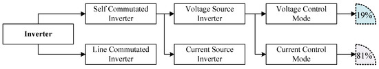
An inverter plays a very prominent role in grid-synchronization and is responsible for DC–AC inversion [1]. Inverters are generally categorized into line commutation inverters (LCI) and self commutation inverters (SCI) based on the commutation process (turned ON and turned OFF behavior). A detailed taxonomy tree of the inverter classification is presented in Figure 1. A figure shows that SCIs are further divided into current source (CSI) and voltage source inverter (VSI). Moreover, VSIs are further divided on the bases for their conduction mode (CM) into current CM (CCM) and voltage CM (VCM). The different classification of inverters is explained through a taxonomy tree in detail in this section [2].
1.1. Line Commutated Inverter
Generally, in LCIs semi-controlled semiconductor devices such as thyristors are used as switches. In semi-controlled switches, the turn ON operation is controlled through the gate terminal whereas the turn OFF characteristics of the switches depends on the circuit parameters i.e., direction of current or voltage polarity. Therefore, in LCI a forced commutation is required to turn OFF the switches. For this purpose, different approaches are presented such as in case of half-bridge LCI an antiparallel diode is attached to enable the force commutation process (to turn OFF the switch) [3].
1.2. Self Commutated Inverter
A MOSFET or IGBT devices are usually used in SCI. MOSFETs are used for high frequency (20–800 kHz) applications having power ratings less than 20 kW. On the contrary, IGBTs are used for low frequency (20 kHz) applications having power ratings greater than 100 kW. The commutation operations of these switches are fully controlled through the gate terminal [4]. Therefore, it controls both the current and voltage output waveforms. High switching frequency devices are preferably used in grid-connected applications to reduce the inverter weight, filter size, and output waveform harmonics [5]. Moreover, SCI improves the grid power factor, suppresses the current harmonics, and shows high robustness to the grid disturbances. Due to the development of sophisticated switching devices and improvement in the control strategies, SCIs are preferably used as compared to LCI. The SCIs are further classified into current source inverter (CSI) and voltage source inverter (VSI).
2.2.1. Current Source Inverter
In CSI, a DC current source is connected as an input to the inverter; hence, the input current polarity remains the same. Therefore, the power flow direction is determined by the input DC voltage polarity. The current waveforms obtained at the output side of CSI are constant in amplitude but variable in width. The main disadvantage of using CSI is the utilization of a large inductor that is connected in series with the input side to handle the current stability issue [6]. The usage of an inductor makes the circuitry less efficient, bulky, and expensive.
2.2.2. Voltage Source Inverter
A DC voltage source is connected as an input to the VSI, hence the input voltage polarity remains the same. Therefore, the direction of input current determines the direction of power flow. The waveforms of an output AC voltage are constant in amplitude but variable in width. Moreover, a major drawback associated with VSI is the usage of a large capacitor that is connected in parallel with the input source [6]. The VSIs are preferably used in grid-tied PV applications as compared to CSIs due to low power losses, high efficiency, low cost, and lightweight. Furthermore, based on their control mode VSIs are operated either in VCM or in CCM.
In VCM, an AC voltage is controlled and maintained at the point of common coupling (PCC). Whereas, in CCM a core control parameter of the controller is the line current and is regulated at PCC. The fault short circuit current in VCM is high as compared to CCM. Moreover, VCM is commonly used in those applications where maintaining the phase, frequency, and voltage at PCC are of major concerns such as off-grid or standalone PV systems. However, both CCM and VCM can be applied to the grid-tied PV VSIs, but the most preferable and commonly used method is CCM [36]. For grid-tied applications, about 81% of VSIs are operated in CCM while only 19% of VSIs are operated in VCM. The reason behind is that the VCM has no control over current while in CCM the current is the main control parameter. Therefore, in case of any grid disturbance, CCM can easily mitigate the current transients and harmonic distortion, and due to its current control structure, it can achieve a high power factor easily [7].
2. Configuration of PV Inverters
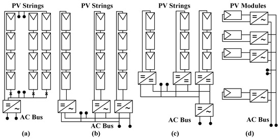
There are many types of PV array configuration in literature such as series, honeycomb, parallel, bridge linked, etc. [8]. Among them, the most commonly used configurations are the series or parallel and series connections. If the PV panels are attached in series with each other it is called a string, and if these are then connected parallel it forms an array. Basically, the PV modules are arranged in four types of configurations based on inverter type [9]. The design characteristics and main characteristics of these inverters are explained below.
2.1. Central Inverter
In this configuration system, to avoid the voltage amplification numerous panels are attached in series to make a string [10]. However, to increase the power level these strings are then attached in parallel to make an array. A complete diagram of the integration of series/parallel PV array with the grid through the central inverter is depicted in Figure 2a [11]. During shading (cloud cover) the PV output voltage are step-up by using a DC–DC boost converter and will be then fed to GCI. The most important drawback of this technology is the usage of a single MPPT for the whole system that causes panels mismatching; thus, the efficiency of the PV system decreases [9]. The other main drawback in this topology is that if the central inverter fails to operate, then the whole PV system will not be able to operate [12]. The central inverters have the lowest overall cost as compared to other configuration systems and are generally used for power ratings between 1–50 MW. Moreover, it shows a high robustness, require less maintenance, and have low AC power losses .
2.2. String Inverter
Currently, string inverter is the most frequently and commonly used technology and considered as a standard in GCPPPs. In this configuration each string is connected independently to the inverter, thus it eliminates the usage of a string diode as presented in Figure 2b [11]. An individual MPPT is applied to every string therefore, partial shading and panels mismatching problems are greatly reduced in this configuration. Consequently, the overall system efficiency increases and is 1–3% higher as compared to the central inverter [13]. The application range of string configuration is up to 5 kW per string. Due to its modular structure, it can be expended to high ratings easily. In this topology, if the string inverter fails to operate it will only affect the operation of its related string rather than the whole PV system like in central configuration. String inverters have high flexibility, high reliability, low DC power and switching losses, and low cable cost. However, the overall cost of this configuration as high as compared to the central configuration due to high installation cost.
2.3. Multi-String Inverter
It is a hybrid configuration, as it combines the beneficial and advantageous features of both string and central inverter configurations. Several strings are individually connected to the converter for voltage amplification (have a separate MPPT system) and are then connected to a centralized or single inverter as shown in Figure 2c [11]. This topology can integrate the PV strings of different orientation and different technologies to a grid. It has high structure modularity; therefore, it can be extended easily to high power ratings by connecting a new PV string to an already existing system [14]. The multi-string topologies are expensive as compared to central inverters but are cheap as compared to module integrated inverters. Multi-string configuration system covers a wide range of PV applications up to 50 kW [15]. However, due to its capability of integrating different ratings of PV strings causes a problem of high voltage variation at the inverter input side.
2.4. Module Integrated or AC Module
An AC module presented in Figure 2d [11] has a low power rating, small in size, and is also known as micro-inverter [2]. AC modules are more suitable and preferably used in low power applications. In AC module, all the functions such as MPPT, voltage amplification, and inversion of DC–AC are performed in a single device called a module. These modules are separately connected at the back of every PV module through MPPT controller to eliminate the mismatch losses [16]. As modules have low power rating therefore high amplified voltage is required which causes a reduction in system’s efficiency. However, this shortcoming can be fully filled by using a highly efficient MPPT technique that makes it the most efficient topology as compared to other three topologies [17]. Due to its modular structure the enlargement can be made easily. As all the functions are carried out in a single module that makes this circuitry complex and requires high initial cost and maintenance.
A detailed comparative analysis of the performance evaluation of all four inverter configurations is made and tabulated in Table 1
| Performance | Central | String | Multi-String | AC Module |
|---|---|---|---|---|
| Very High | Variation of DC input voltage | ------ | ------ | Maintenance Installation cost MPPT efficiency Flexibility Reliability |
| High | Cables cost Voltage balancing DC power loss Switching loss Panels mismatching Robustness |
Installation cost MPPT efficiency Flexibility Reliability |
Variation of DC input voltage | AC Cables cost AC Power loss |
| Medium | Installation cost | DC Cables cost DC voltage variation AC Power loss Voltage balancing |
Maintenance MPPT efficiency Flexibility Reliability Robustness DC and AC power loss Switching loss Installation and cables cost |
------ |
| Low | MPPT efficiency Flexibility Reliability Maintenance AC Power loss |
Robustness Cables cost DC Power loss Switching loss Panels mismatching |
Voltage balancing Panels mismatching |
Voltage balancing |
| Very low | ------ | ------ | ------ | Robustness Cables cost DC voltage variation DC Power loss Switching loss Panels mismatching |
| Power rating | 1–50 MW | 1–5 kW/string | 1–50 kW | 500–600 W |
| Cost | Lowest cost | Costly than centralized inverter | Costly than centralized inverter | Highest cost |
This entry is adapted from the peer-reviewed paper 10.3390/en13164185
References
- Liu, H.; Zhou, B.; Li, Y.; Chen, J.; Loh, P.C. High-Efficiency T-Source Inverter With Low Voltage Spikes Across the Switch Bridge. IEEE Trans. Power Electron. 2020, 35, 10554–10566.
- Al-Shetwi, A.Q.; Sujod, M.Z.; Blaabjerg, F.; Yang, Y. Fault ride-through control of grid-connected photovoltaic power plants: A review. Sol. Energy 2019, 180, 340–350.
- Ishikawa, T. Grid-Connected Photovoltaic Power Systems: Survey of Inverter and Related Protection Equipments; IEA-PVPS-T5-05: Paris, France, 2002; p. 64.
- Calais, M.; Agelidis, V.G.; Meinhardt, M. Multilevel converters for single-phase grid-connected photovoltaic systems: An overview. Sol. Energy 1999, 66, 325–335.
- Erickson, R.W.; Maksimovic, D. Fundamentals of Power Electronics, 3rd ed.; Springer Science & Business Media: Berlin, Germany, 2007; ISBN 978-1-4757-0559-1.
- Azmi, S.A.; Ahmed, K.H.; Finney, S.J.; Williams, B.W. Comparative analysis between voltage and current source inverters in grid-connected application. In Proceedings of the IET Conference on Renewable Power Generation (RPG 2011), Edinburgh, UK, 6–8 September 2011; p. 101.
- Hojabri, M.; Soheilirad, M.S. Harmonic Distortion in an Off-Grid Renewable Energy System with Different Loads. In Proceedings of the International MultiConference of Engineers and Computer Scientists 2014, Hong Kong, 12–14 March 2014; pp. 1–6.
- Wang, Y.-J.; Hsu, P.C. An investigation on partial shading of PV modules with different connection configurations of PV cells. Energy 2011, 36, 3069–3078.
- Kouro, S.; Leon, J.I.; Vinnikov, D.; Franquelo, L.G. Grid-Connected Photovoltaic Systems: An Overview of Recent Research and Emerging PV Converter Technology. IEEE Ind. Electron. Mag. 2015, 9, 47–61.
- Kjaer, S.B.; Pedersen, J.K.; Blaabjerg, F. A Review of Single-Phase Grid-Connected Inverters for Photovoltaic Modules. IEEE Trans. Ind. Appl. 2005, 41, 1292–1306.
- Mohd.Ali, J.S.; Krishnaswamy, V. An assessment of recent multilevel inverter topologies with reduced power electronics components for renewable applications. Renew. Sustain. Energy Rev. 2018, 82, 3379–3399.
- Kjaer, S.B., Pedersen, J.K.; Blaabjerg, F. Power inverter topologies for photovoltaic modules-a review. In the Proceedings of the Conference Record of the 2002. IEEE Industry Applications Conference. 37th IAS Annual Meeting (Cat. No.02CH37344), Pittsburgh, PA, USA, 13–19 October 2002.
- Myrzik, J.M.; Calais, M. String and module integrated inverters for single-phase grid connected photovoltaic systems-a review. In Proceedings of the 2003 IEEE Bologna Power Tech Conference Proceedings; Bologna, Italy, 23–26 June 2003; pp. 8
- Meinhardt, M.; Cramer, G. Past, present and future of grid-connected photovoltaic- and hybrid-power-systems. In Proceedings of the 2000 Power Engineering Society Summer Meeting (Cat. No.00CH37134), Seattle, WA, USA, 6 August 2000; pp. 1–6.
- Calais, M.; Myrzik, J.; Spooner, T.; Agelidis, V.G. Inverters for single-phase grid-connected photovoltaic systems-an overview. In Proceedings of the 2002 IEEE 33rd Annual IEEE Power Electronics Specialists Conference. Proceedings (Cat. No.02CH37289), Cairns, Qld, Australia, Australia, 23–27 June 2002; pp. 1995–2000.
- Verhoeven, B. Utility Aspects of Grid Connected Photovoltaic Power Systems; International Energy Agency: Paris, France, 1998.
- Elrayyah, A.; Sozer, Y.; Elbuluk, M. Microgrid-Connected PV-Based Sources: A Novel Autonomous Control Method for Maintaining Maximum Power. IEEE Ind. Appl. Mag. 2015, 21, 19–29.