Your browser does not fully support modern features. Please upgrade for a smoother experience.
Please note this is an old version of this entry, which may differ significantly from the current revision.
Subjects:
Engineering, Mechanical
Hybrid Construction Machinery (HCM), known as an effective and crucial solution for the issues of environment pollution and energy shortage. Central feature is the drive system of the construction machinery consists of two or more independent drive systems that can work simultaneously.
- hybrid powered system
- energy storage system
- construction machinery
1. Introduction
Originally conceived by the automobile industry, hybrid power technologies have become increasingly mature through decades of development. In the field of construction machinery, hybrid power technology is considered an important candidate to address the issues of high energy consumption and high emission. According to the development of hybrid construction machinery (HCM) in Figure 1 [1], the research of HCM had a relatively late start. With the introduction of hybrid technology from the automotive field and a large number of researchers that have devoted themselves to related research, HCM has developed rapidly over the past decade.
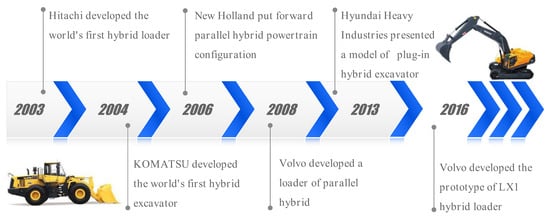
Figure 1. Development history of HCM (hybrid loaders and excavators) [1].
The classification and structural characteristics of energy storage systems were introduced in [2]. Based on the above works, hybrid electric excavator, loader, forklift, bulldozer and crane systems were introduced in [3]. The existing review papers have mostly analyzed and compared the structural characteristics of HCM systems and subsystems. In addition, there has been no systematical and comprehensive overview of energy management strategies in HCM hybrid technology.
Compared with common automobiles, construction machinery is characterized by lower travel speed, more obvious periodicity, higher amplitude and load change rate, more complex systems and structures, as well as more frequent start-stop operations [1][4], as listed in Table 1.
| Characteristic | Construction Machinery | Automobile |
| Travel speed | Low | High |
| Periodicity | √ | × |
| Load | Changes sharply and frequently | Changes smoothly |
| Weight | There may be huge differences between products or models | The difference is relatively small. |
| System | Mechanical system; Hydraulic system; Electrical system; Control system. |
Mechanical system; Electrical system; Control system. |
| Structure | Complex (Existence of different actuators) |
Simple (No actuator) |
| Start-stop | Very frequent (Including travel device and actuator) |
Not so frequent |
| Fuel consumption and emission | High | Low |
Besides, the duty cycle (defined as the proportion of high load status to total period) of actuators is low (e.g., under typical operation cycle, the duty cycle of a wheel loader is only about 60%, and the remaining time is in a low load or non-load state [3]). A large number of actuators participate in the operation process, making the working conditions, systems and structures of construction machinery more complex than those of automobiles. Besides, there are many differences between different construction machineries, further increasing the complexity of the problem. Accordingly, the characteristics of construction machinery should be fully captured and hybrid power systems suitable for construction machinery should be developed.
2. Configuration of HCM
HCM, as a composite system, integrates knowledge about machinery, electricity, heat, liquids and chemistry. During its operation, complicated power flow, energy flow and information flow are generated, transmitted and transformed. Configuration is the basis of hybrid power system design, determining the development and selection of energy management strategy. Thus, it is necessary to differentiate the configuration of hybrid power systems in a reasonable manner before studying the energy management strategy for HCMs.
According to the structure, the hybrid electric vehicle (HEV) transmission system is split into series, parallel and series-parallel (power split). Due to the existence hydraulic actuators in HCM, the system configuration topology is a two-dimensional matrix, consisting of drive train and hydraulics, as shown in Figure 2. However, in a HCM system, this two-dimensional configuration expression is not only cumbersome, but also lacks any description of the energy characteristics of the system. Besides, it is not clearly expressed because of the lack of description of the energy characteristics of HCM system. Accordingly, applying the classification concepts of HEVs directly to HCMs may complicate the accurate expression of the configuration.
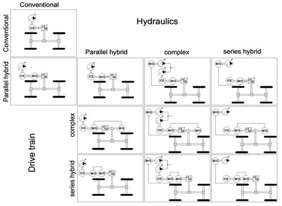
Figure 2. Combination matrix of hybrid topologies [5].
To deal with the classification problem of HCMs, according to the type of hybrid power-energy source, they are classified into three types, including Diesel-hydraulic hybrid (DHH), Diesel-electric hybrid (DEH) and fuel cell hybrid (FCH). This classification method reflects the ways and characteristics of energy conversion, storage and utilization in each HCM system. In a HCM system, the energy generating device covers ICE and fuel cell, and the energy storage system (ESS) primarily includes storage batteries, super capacitors and hydraulic accumulators. The performance characteristics of energy storage devices (as shown in Figure 3) lay a solid basis for HCM to formulate energy management strategy constraints. Thus, the combination of energy-based and structure-based classification in Table 2 can help to achieve a more accurate and reasonable description of HCM system configuration.
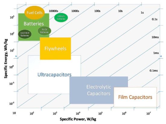
Figure 3. Specific energy and specific power of ESS [6].
| - | DEH | DHH | FCH |
|---|---|---|---|
| Series hybrid |  |
 |
 |
| Parallel hybrid | 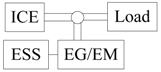 |
 |
_ |
| Series-parallel hybrid |  |
 |
_ |
1Note.  mechanical connection;
  electrical connection;
  hydraulic connection.
mechanical connection; electrical connection; hydraulic connection.2.1. Diesel-Electric Hybrid
According to the definition of the International Electrotechnical Commission, a HEV is a vehicle with two or more forms of energy reserves, one of which can be converted into electric energy [10]. Like HEVs, DEH adopts a battery or ultracapacitor as ESS [7]. The use of fossil energy is reduced in DEH by combining hydraulic energy and electric energy during operation. The DEH structure consists of ICE, generator, battery /ultracapacitor, motor and hydraulic actuator. Under this structure, the ICE converts the energy of diesel oil and charges the ESS [11].
In the recent decades, the continuous development of HEV technology has stimulated the use of DEH in HCM. The hybrid excavator has been outfitted with the capacitor to balance the fluctuation of the power required by the hydraulic system and to store the regenerative energy of the hydraulic motor-generator and the swing motor [12]. However, due to the low capacity, capacitors cannot easily satisfy the requirements of HCM systems. Referencing the design idea of HEV [13], the series and parallel topologies of DEH are shown in Figure 4 and Figure 5, respectively [14][15].
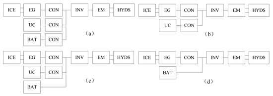
Figure 4. Schematic structures of series hybrid excavator [15].
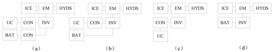
Figure 5. Schematic structures of parallel hybrid excavator [16].
In [15], by combining test and simulation, the performance of excavator in series, parallel and conventional structures is compared, in which the series structure adopts Figure 4d and the parallel one follows Figure 5d. The comparison results of [15] reveal that the ICE in series structure performs better under heavy load mode, because ICE is not coupled with actuators or affected by load fluctuation. Furthermore, if the economy is further considered, the current in the series structure changes more dramatically than in the parallel one, which negatively affects battery life and increases maintenance costs. It is considered that parallel structure is more applicable to hybrid excavators. Accordingly, the structure of Figure 5d is presented in relevant studies [16][17].
However, the impact of the frequent changes in HCM load on battery-based ESS may be greater than expected. For instance, it only takes 2–3 sec. for the excavator boom to descend, during which the electrochemical reaction process of the battery is slow (typical response time ranges are 2–3 s [18]), and the high power charging is difficult [2]. Thus, frequent high-power and fast impulse/discharge of energy is a problem to be solved for battery as ESS in HCM. Compared with batteries, ultracapacitors possess the characteristics of fast response (with a response time of milliseconds [19]), higher power density and better temperature adaptation [20]. Ultracapacitors are more efficient than batteries because there is no chemical reaction during energy storage. The progress of the preparation technology of mesoporous materials improves the performance of ultracapacitor [21] and promote the structures in Figure 4b and Figure 5c applied in engineering [22][23].
In view of the problem of low energy density and high cost of ultracapacitors, a scheme combining battery and ultracapacitor was proposed [24][25], in which the battery and ultracapacitor were connected in parallel on DC bus like in Figure 4a. The energy allocation of the system by thw ultracapacitor can decrease the battery cycle and power ramp rates, thus improving the comprehensive performance of ESS, but in this case, the limitation of voltage change from battery affects the energy recovery of the ultracapacitor. Hredzak [26] et al. adopted two bidirectional DC/DC converters. Ultracapacitor and battery can be charged and discharged independently, enhancing the flexibility of the energy management control strategy. The ultracapacitor is regarded as an energy buffer to ensure stable battery charging and discharging [27]. The combination of ultracapacitor and battery is complementary and reduces the capacity requirement of the ultracapacitor, thereby reducing the cost. Nevertheless, some problems remain regarding installation space and weight, and the addition of different energy storage devices may increase the difficulty of energy management.
In the design of ESS for DEM, several aspects (e.g., capacity design, charging and discharging power and voltage design) should be considered. Given the corresponding characteristics of ESS, the total capacity should match the requirements of continuous charging and discharging. Besides, the system voltage should be matched with the motor and transformer used. The maximum charging and discharging power required can be obtained from the power spectrum analysis of working conditions and ensured when designing the charging and discharging current of battery packs or ultracapacitor. Then, according to the requirements of capacity and charging and discharging current, the battery or ultracapacitor can be selected reasonably.
2.2. Diesel-Hydraulic Hybrid
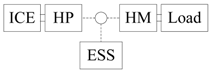
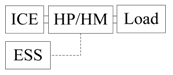
Considerable electric power and electronic equipment have been added to DEH systems, increasing the difficulty and cost of system transformation. In engineering applications, DHH systems were used in the initial stage of technology introduction. The difference between DHH and DEH lies in the types of ESS and energy flow, i.e., hydraulic system, hydraulic pump/motor and hydraulic accumulator act as auxiliary power source components. As a type of hydraulic energy storage device, an accumulator is also used as the hydraulic counterbalance of the boom to balance the gravity of the working device [28]. In DHH systems, hydraulic energy can be converted into mechanical energy through a hydraulic pump/motor and couple with the energy output from the ICE to form a "torque coupling structure” (TCS) similar to a parallel DEH [29], as shown in Figure 6. On the other hand, the hydraulic energy between accumulator and main pump can also be coupled directly, which is termed as a "flow coupling structure” (FCS) [30], as shown in Figure 7.
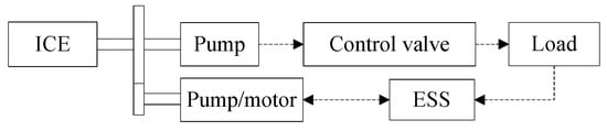
Figure 6. Torque coupling structure [29].
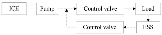
Figure 7. Flow coupling structure [30].
In the design of DHH, to meet the design requirements of the system, additional accumulators were added in the DHH system, and different effects were generated. A TCS system with double accumulators was applied in [31] and [32], as shown in Figure 8. High-pressure (HP) accumulator was used to recover and store excess energy of ICE, braking energy of rotary motor and energy recovered from the cylinder circuit, which could generate the torque for the system through a hydraulic pump/motor working in the motor mode coupled with the engine or provide oil for the rotary motor in the form of flow coupling when the rotary motor starts. The additional low-pressure (LP) accumulator was not used for energy storage but rather used as a low pressure flow source to achieve the balance of the flow of each cylinder. The simulation results suggest that the system can save up to 27% of the fuel consumption compared with the non-hybrid system. In [30], a FCS system with two accumulators was introduced, as shown in Figure 9. The two accumulators were used to recover the potential energy of the boom and the rotating braking energy, respectively, and the flow can be shared between the accumulators to maintain the ideal state of charge (SOC) and maximize the energy recovery. For instance, when the pressure of the boom potential energy recovery accumulator is too large, the excess oil recovered can be transferred to the rotary brake energy recovery accumulator. When the revolutions start and the boom rises, the accumulators will release the stored oil to the outlet of the hydraulic pump, which attempts to supplement the power required in the instantaneous start-up and reduce the power demand of the hydraulic pump for energy saving. The energy-saving effect of the system could increase to 10.1% with appropriate flow distribution control strategy. In other designs, excessive throttling of FCS hydraulic system was avoided, and throttling loss was reduced by introducing a new valve configuration with two pressure levels of accumulator, medium pressure (MP) and high pressure (HP) [33].
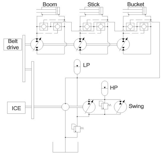
Figure 8. TCS system with double accumulators [31].
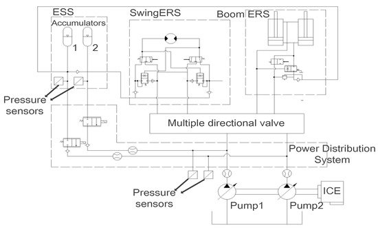
Figure 9. FCS system with two accumulators [30].
In addition to multi-accumulator systems, a hydraulic/electric synergy system composed of accumulators and batteries was proposed [34][35]. As the boom of an excavator descends, the starting and stopping state of the engine depends on the pressure in the accumulator and does not affected by the boom. In this process, the accumulator limits the operating point of the ICE to an efficient field, allowing the system to apply lower power engines and motors. Furthermore, the impact of energy flow is absorbed by accumulator, decreasing the change rate and the amplitude of charging current. The time to regenerate energy is significantly increased from 2 sec. to 20 sec. Compared with DEH, the hydraulic/electric synergy system further reduces the cost.
Compared with DEH, DHH technology involves less energy conversion behavior, reducing the energy losses of the system. Besides, the hydraulic/electric synergy system can further reduce the cost. Moreover, in the trend of technology upgrading and stricter emission standards [36], FCS, because of its low cost of system modification, has promising applications in remanufacturing. The coupling condition of accumulator and the major hydraulic pump in FCS is that the former pressure is greater than the latter’s outlet pressure, limiting the reuse of energy.
2.3. Fuel Cell Hybrid
As one of the alternatives to ICE in the future, the application of fuel cells in engineering machinery is also being developed [36][37], during which the characteristics of fuel cell should be considered. Take the proton exchange membrane fuel cell (PEMFC) as an example, in which the pressure and humidity should be controlled using the corresponding devices. The dynamic response of PEMFC is slow due to the limitation of the reaction speed of the devices. In the case of abrupt load change, the response delay will cause the output voltage and current of fuel cell to not change rapidly with the energy demand of the system. Accordingly, it is necessary to consider the system response delay in the application of fuel cell technology.
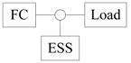
One of the effective ways to solve the mentioned problems is to compensate the response lag of fuel cell system by exploiting the high responsiveness of ESS, which is termed a fuel cell hybrid (FCH) system. In [38], the topological system for a FCH was given, as shown in Figure 10, and its structure is more concise than that of diesel hybrid power system. The power of conventional ICEs in construction machinery was replaced by the power of fuel cells and ESS. Due to the fact the working point of a fuel cell varies with the capacity of the fuel cell and ESS, the capacity of the fuel cell and ESS should be allocated in a reasonable manner with the power demand is met. In [39], a strategy of optimal capacity allocation for FCH excavators based on dynamic programming was proposed. The simulation results show that as the number of cells increases, the hydrogen fuel consumption decreases, the final SOC of ESS is easier to maintain at a set value. However, too many cells will reduce the power consumption of ESS and make the SOC unsustainable. Following this strategy, the optimal solution was obtained from three aspects of comprehensive evaluation, including final SOC, fuel cell efficiency and cost.
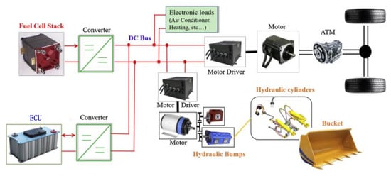
Figure 10. Topology of the electrical system for FCH [38].
Furthermore, the load change and start-stop cycling are the primary factors leading to the performance degradation of fuel cells [40]. The efficient use of ESS is the key to reduce the impact of variable load and start-stop cycle on fuel cell life. Zhang [41] et al. proposed a DC bus voltage control energy management strategy and applied it in a FCH forklift. This strategy, due to the reaction delay of fuel cells, could prevent voltage overshoot or undershoot during the charging and discharging process of ESS, thus protecting the system and enhancing efficiency.
This entry is adapted from the peer-reviewed paper 10.3390/en12102024
References
- Wang, J.; Yang, Z.; Liu, S.; Zhang, Q.; Han, Y. A Comprehensive overview of hybrid construction machinery. Adv. Mech. Eng. 2016, 8, 1–15.
- Lin, T.; Chen, Q.; Ren, H.; Huang, W.; Chen, Q.; Fu, S. Review of boom potential energy regeneration technology for hydraulic construction machinery. Renew. Sustain. Energy Rev. 2017, 79, 358–371.
- He, X.; Jiang, Y. Review of hybrid electric systems for construction machinery. Autom. Constr. 2018, 92, 286–296.
- Lin, T.; Wang, Q.; Hu, B.; Gong, W. Development of hybrid powered hydraulic construction machinery. Autom. Constr. 2010, 19, 11–19.
- Filla, R. Hybrid Power Systems for Construction Machinery: Aspects of System Design and Operability of Wheel Loaders. In Proceedings of the ASME 2009 International Mechanical Engineering Congress & Exposition, Lake Buena Vista, FL, USA, 13–19 November 2009; pp. 611–620.
- Das, H.S.; Tan, C.; Yatim, A.H.M. Fuel cell hybrid electric vehicles: A review on power conditioning units and topologies. Renew. Sustain. Energy Rev. 2017, 76, 268–291.
- Frank, B. Using Optimal Control in Concept Evaluation and System Optimization of Diesel-Electric Hybrid Construction Machines. In Proceedings of the 2016 International Conference on Electrical Systems for Aircraft, Railway, Ship Propulsion and Road Vehicles & International Transportation Electrification Conference, Toulouse, France, 2–4 November 2016.
- De Oliveira, L.A.; de Almeida D’Agosto, M.; Fernandes, V.A.; de Oliveira, C.M. A financial and environmental evaluation for the introduction of diesel-hydraulic hybrid-drive system in urban waste collection. Transp. Res. Part D Transp. Environ. 2014, 31, 100–109.
- Zhang, J.; Lv, C.; Qiu, M.; Li, Y.; Sun, D. Braking energy regeneration control of a fuel cell hybrid electric bus. Energy Convers. Manag. 2013, 76, 1117–1124.
- Chau, K.T.; Wong, Y. Overview of power management in hybrid electric vehicles. Energy Convers. Manag. 2002, 43, 1953–1968.
- Nilsson, T.; Froberg, A.; Aslund, J. Predictive control of a diesel electric wheel loader powertrain. Control Eng. Pract. 2015, 41, 47–56.
- Lin, T.; Masami, O.; Liu, X.; Wang, Q.; Hu, B.; Gong, W. Research on parallel hybrid hydraulic excavator with energy regeneration system. In Proceedings of the Seventh International Conference on Fluid Power Trasmission and Control, Hangzhou, China, 7–10 April 2009.
- Lam, L.T.; Louey, R. Development of ultra-battery for hybrid-electric vehicle applications. J. Power Sources 2006, 158, 1140–1148.
- Nanjo, T.; Imanishi, E.; Kagoshima, M. Power simulation on the actual operation in hybrid excavator. Trans. -Soc. Automot. Eng. Jpn. 2004, 35, 101–106.
- Wang, D.; Guan, C.; Pan, S.; Zhang, M.; Lin, X. Performance analysis of hydraulic excavator powertrain hybridization. Autom. Constr. 2009, 18, 249–257.
- Wang, D.; Guan, C. Optimal Control for a Parallel Hybrid Hydraulic Excavator Using Particle Swarm Optimization. Sci. World J. 2013, 2013, 831564.
- Lin, X.; Pan, S.-X.; Wang, D.-Y. Dynamic simulation and optimal control strategy for a parallel hybrid hydraulic excavator. J. Zhejiang Univ.-Sci. A 2008, 9, 624–632.
- Hernandez, J.C.; Bueno, P.G.; Sanchez-Sutil, F. Enhanced utility-scale photovoltaic units with frequency support functions and dynamic grid support for transmission systems. IET Renew. Power Gen. 2017, 11, 361–372.
- Hernandez, J.C.; Sanchez-Sutil, F.; Vidal, P.G.; Rus-Casas, C. Primary frequency control and dynamic grid support for vehicle-to-grid in transmission systems. Int. J. Electr. Power Energy Syst. 2018, 100, 152–166.
- Wang, C.; He, H.; Zhang, Y.; Mu, H. A comparative study on the applicability of ultracapacitor models for electric vehicles under different temperatures. Appl. Energy 2017, 196, 268–278.
- Wang, L.; Ding, W.B.; Sun, Y.B. The preparation and application of mesoporous materials for energy storage. Mater. Res. Bull. 2016, 83, 230–249.
- Wang, H.; Huang, Y.; Khajepour, A.; He, H.; Cao, D. A novel energy management for hybrid off-road vehicles without future driving cycles as a priori. Energy 2017, 133, 929–940.
- Kim, H.; Yoo, S.; Cho, S.; Yi, K. Hybrid control algorithm for fuel consumption of a compound hybrid excavator. Autom. Constr. 2016, 68, 1–10.
- Truong, B.N.; Truong, D.Q.; Young, L.S.; Young, L.S.; Kwan, A.K.; Thanh, T.Q. Study on Energy Regeneration System for Hybrid Hydraulic Excavator. In Proceedings of the 2015 International Conference on Fluid Power and Mechatronics, Harbin, China, 5–7 August 2015.
- Yoon, J.I.; Dinh Quang, T.; Ahn, K.K. A generation step for an electric excavator with a control strategy and verifications of energy consumption. Int. J. Precis. Eng. Manuf. 2013, 14, 755–766.
- Hredzak, B.; Agelidis, V.G.; Jang, M. A Model Predictive Control System for a Hybrid Battery-Ultracapacitor Power Source. IEEE Trans. Power Electron. 2014, 29, 1469–1479.
- Chen, J. Energy Efficiency Comparison between Hydraulic Hybrid and Hybrid Electric Vehicles. Energies 2015, 8, 4697–4723.
- Chen, M.; Zhao, D. The gravitational potential energy regeneration system with closed-circuit of boom of hydraulic excavator. Mech. Syst. Signal Process. 2017, 82, 178–192.
- Xiao, Y.; Guan, C.; Li, P.Y.; Wang, F. Optimal Design of a Compound Hybrid System consisting of Torque Coupling and Energy Regeneration for Hydraulic Hybrid Excavator. In Proceedings of the 2015 IEEE/ASME International Conference on Advanced Intelligent Mechatronics, Susan, Korea, 7–11 July 2015.
- Xiao, Y.; Guan, C.; Lai, X. Research on the design and control strategy for a flow-coupling-based hydraulic hybrid excavator. Proc. Inst. Mech. Eng. Part D J. Automob. Eng. 2014, 228, 1675–1687.
- Hippalgaonkar, R.; Ivantysynova, M. A Series-Parallel Hydraulic Hybrid Mini-Excavator with Displacement Controlled Actuators. In Proceedings of the 13th Scandinavian International Conference on Fluid Power, Linköping, Sweden, 3–5 June 2013.
- Zimmerman, J.; Hippalgaonkar, R.; Ivantysynova, M. Optimal control for the series-parallel deplacemant controlled hydraulic hybrid excavator. In Proceedings of the ASME Dynamic Systems and Control Conference and Bath/Asme Symposium on Fluid Power and Motion Control, Arlington, VA, USA, 31 October–2 November 2012.
- Leifeld, R.; Vukovic, M.; Murrenhoff, H. Hydraulic Hybrid Architecture for Excavators. ATZoffhighway Worldw. 2016, 9, 44–49.
- Lin, T.L.; Wang, Q.F.; Hu, B.Z.; Gong, W. Research on the energy regeneration systems for hybrid hydraulic excavators. Autom. Constr. 2010, 19, 1016–1026.
- Sun, H.; Yang, L.; Jing, J. Hydraulic/electric synergy system (HESS) design for heavy hybrid vehicles. Energy 2010, 35, 5328–5335.
- Xiao, L.; Liu, W.; Guo, Q.; Gao, L.; Zhang, G.; Chen, X. Comparative life cycle assessment of manufactured and remanufactured loading machines in China. Resour. Conserv. Recycl. 2018, 131, 225–234.
- Shin, M.; Eom, T.; Park, Y.; Won, C. Design and Control of Fuel Cell-Battery Hybrid System for Forklift. In Proceedings of the 2016 IEEE Transportation Electrification Conference and Expo, Busan, Korea, 1–4 June 2016.
- Li, T.; Liu, H.; Zhao, D.; Wang, L. Design and analysis of a fuel cell supercapacitor hybrid construction vehicle. Int. J. Hydrog. Energy 2016, 41, 12307–12319.
- Yi, H.; Jeong, J.; Cha, S.; Zheng, C. Optimal Component Sizing of Fuel Cell-Battery Excavator Based on Workload. Int. J. Precis. Eng. Manuf.-Green Technol. 2018, 5, 103–110.
- Pei, P.; Chang, Q.; Tang, T. A quick evaluating method for automotive fuel cell lifetime. Int. J. Hydrog. Energy 2008, 33, 3829–3836.
- Zhang, Z.; Mortensen, H.H.; Jensen, J.V.; Andersen, M.A.E. Fuel Cell and Battery Powered Forklifts. In Proceedings of the 2013 9th IEEE Vehicle Power and Propulsion Conference, Beijing, China, 15–18 October 2013.
This entry is offline, you can click here to edit this entry!