Your browser does not fully support modern features. Please upgrade for a smoother experience.
Please note this is an old version of this entry, which may differ significantly from the current revision.
Subjects:
Engineering, Electrical & Electronic
脑机接口(BCI)是近年来出现的,并引起了极大的关注。脑电极作为脑机接口信号采集系统中不可缺少的组成部分,其对信号质量的影响很大,决定了最终的效果。由于脑电极的特殊使用场景,它们需要一些特定的属性。
- brain-electrode interface
- EEG electrodes
- dry electrodes
- wet electrodes
- semi-dry electrodes
一、介绍
BCI 是一种具有多学科联系的新技术,包括材料、神经科学、信号处理等。应用情绪波动产生的神经活动来驱动外部应用工作。BCI 的概念由 Jacques Vidal 于 1973 年提出 [ 2 ]。此外,1977年Vidal实现了利用大脑通过ERP(事件相关电位)直接控制计算机屏幕上迷宫中二维点的运动[ 3 ]。1998 年第一次 BCI 国际会议提出了一个详细定义:脑机接口为其用户提供了通信和控制通道,不依赖于大脑周围神经和肌肉的正常输出通道 [ 4 ]。
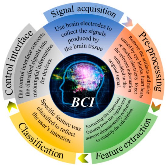
BCI 最初旨在为残疾人提供便利。如今,BCI 可用于许多领域,包括医学、娱乐、工业和其他应用。医疗领域是目前其中BCI施加[面积最大5,6,7 ]。例如,它可以用作替代交流和环境控制,使肌萎缩侧索硬化 (ALS) 患者能够交流 [ 8 ] 或用于中风后运动康复 [ 9 , 10 ]。BCI 也可以治疗抑郁症等精神疾病 [ 11]]。此外,BCI 还可以测试不同环境下的工作难度,例如通过脑电活动预测玩俄罗斯方块的难度 [ 12 ],评估外科医生在简单和复杂的手术训练任务中的压力负荷变化 [ 13 ],检测驾驶员'驾驶疲劳程度[ 14 ],实词课堂学生持续注意力评价[ 15 ]。BCI在游戏领域也有一些初步的应用[ 16 ],例如用脑电图控制射箭[ 17 ]以及通过BCI实现多人在线VR赛车游戏[ 18]]。此外,还有游戏结合医疗训练系统,用于分析或改善儿童在阅读过程中的注意力缺陷和多动障碍[ 19 ]。作为第一个 BCI 应用,BCI 拼写器近年来得到了广泛的应用,如本综述所示 [ 20 ]。然而,大多数这些应用只能在实验室中实现。从这些技术中,我们可以看到无数的可能性和巨大的挑战。如图1所示, 信号的获取是BCI的第一步,也是最重要的部分。
The quality of the signals directly determines the difficulty of the subsequent work and the final effect of the whole system. The brain electrodes remain an important technological challenge and the current focus of BCI research. At present, BCI signal sensor modalities mainly include implanted microelectrodes, ECoG (electrocorticography), intravascular electrodes, EEG (electroencephalogram), fMRI (functional magnetic resonance imaging), fNIRS (functional near-infrared spectroscopy), fTCD (functional transcranial doppler), MEG (magnetic encephalography), and PET (positron emission tomography) [27]. The electrical sensor modalities are commonly used at present.
Invasive electrodes were first applied to neurology examinations resulting from their most perfect signal because they can penetrate specific regions of the brain parenchyma to measure neuronal electrophysiological activity. The shorter distance between the neurons and the electrodes suggests better brain electrical signals due to less interference in the signal transmission path. Therefore, many BCIs in the early stage used invasive electrodes as electrical signal acquisition methods. The materials used for invasive electrodes have developed from metal wire [28,29,30,31,32,33] to silicon-based microprobes [34,35,36,37,38]. At present, conductive materials located on a substrate made of soft materials with good biocompatibility especially biomaterials such as alginate, chitosan, collagen, and cellulose have become the ideal choice [39,40]. The final failure of invasive recording is usually attributed to the coupling of both abiotic and biotic perspectives [33]. The abiotic factor implies the electrode will eventually expire. Large variation in electrode impedance and appearance, as well as structural changes on the electrodes’ recording surface, were observed after several weeks of implanting. Biotic problems occur even at the very beginning of the implantation, including, but not limited to, direct lesions or induced inflammation.
2. EEG Electrodes
The non-invasive technique is the commercial signal acquisition method currently used in BCI. By placing brain electrodes on the surface of the scalp, an electroencephalogram (EEG) can be recorded without invading brain tissue. What follows is that the EEG signal amplitude will be much smaller than that which was recorded by invasive electrodes due to the interference caused by the cranium, skin tissue, and hair. Because of its low trauma, or even non-trauma to the human body, non-invasive electrodes have gradually become the mainstream application of BCI electrodes. As shown in Figure 2, there are three main types of non-invasive electrodes including wet electrodes, dry electrodes, and emergent semi-dry electrodes according to different conditions of use.
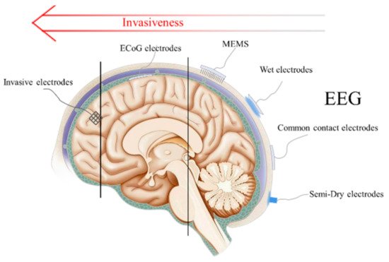
Figure 2. Schematic diagram and invasiveness degree of EEG electrodes, ECoG electrodes and invasive electrodes.
2.1. Principle of EEG Acquisition
Brain electric activity mainly comes from postsynaptic potentials. The brain electrical current is generated by the flow of Na+ K+ Ca++ Cl−, leading to the electric dipole. The electrical activity signal of a single neuron is so weak that only the sum of the electrical activities of numerous neurons can be detected [45]. EEG is the potential difference between two electrodes put on the scalp as shown in Figure 3.
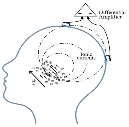
Figure 3. Schematic diagram of the EEG acquisition.
A basic EEG acquisition system usually consists of three electrodes including an active electrode (A), a reference electrode (R), and a grounding electrode (G). The AG potentials and RG potentials are then connected to a differential amplifier to eliminate environmental electrical activity. Therefore, EEG not only reflects the electrical activity on where the active electrode is placed but also the potential difference between the location of the active electrode and the reference electrode. According to the recommendations of the American Electroencephalography Society, active electrodes are not randomly placed on the brain but are based on the international 10–20 system (as shown in Figure 4) [46].
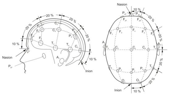
Figure 4. Electrode placement over scalp according to the international 10–20 system [46].
The amplitude of the scalp EEG is usually less than 100 μV. In daily applications, although the differential amplifier circuit can remove most of the noise, the residual noise will still distort the result due to the difference between the electrodes and the limitation of the amplifier performance. Generally, the desired signal can be separated from the background noise by averaging signals. However, for applications such as BCI that require an immediate response, increasing the number of measurement times is not a reliable choice. After the signal is collected, there will be pre-processing for the signal such as filtering, but filtering will distort the result in many aspects. For instance, the filter may change the start and end time of a waveform and may cause the original single-phase transform to become multiphase. Therefore, it is very important to obtain clear data at the electrode directly.
In general, contact impedance will directly affect EEG collection. The well-known resistance is only suitable for the concept of direct current. Additionally, in the acquisition of an EEG, the potential constantly changes with time, so the inductance and capacitance will also hinder the current, which is collectively defined as impedance. In the context of EEG recording, impedance is typically measured by passing a small 10 Hz current closed to the EEG frequency between two electrodes [47].
Impedance has the following effects on signal acquisition. Firstly, the high impedance will significantly reduce the common-mode rejection ratio (CMRR), which determines the ability to suppress the common noise of the working electrode and the reference electrode caused by lights, video displays, and so on. However, the CMRR can be enhanced by increasing the input impedance of the amplifier because the larger the input impedance, the closer the input voltage obtained by the amplifier circuit to the signal source voltage. However, the input impedance ought not to reach an exceedingly high level because the current will become susceptible to any electromagnetic disturbances. Therefore, the input impedance also has a certain adjustment range, and the skin contact impedance should be reduced as much as possible. Secondly, the high impedance will cause a great drift in the skin potential. This noise cannot be eliminated by common-mode suppression such as human body movement and environmental electrical noise. The skin potential of each electrode’s contact part, in turn, depends on factors such as the thickness of the skin, the number of sweat glands and hair follicles, and the degree of skin hydration [48,49]. Any difference in the conductance of the skin will lead to a different voltage offset for each electrode. Low-contact impedance will condense the skin potential drift and abate the noise. Figure 5 clearly describes the impedance composition of different electrode–skin interface models under different EEG electrodes.
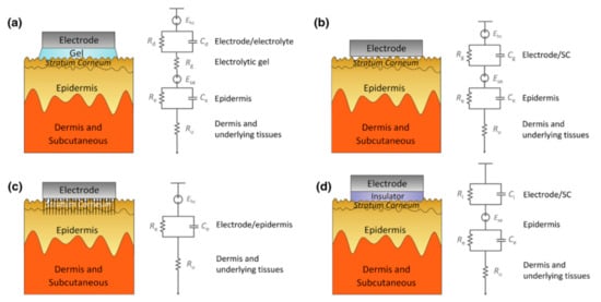
Figure 5. Schematics and corresponding electrode–skin interface models for EEG electrodes. (a) Wet electrodes, (b) MEMS electrodes, (c) non-contacted electrodes, and (d) common-contact dry electrodes [50].
2.2. Wet Electrodes
As the name suggests, wet electrodes need a conductive paste dissolved in the stratum to decrease impedance so that there is better contact between the electrodes and the skin. Due to the decrease in impedance, the quality of the signal collected by wet electrodes is much better than that of dry electrodes. In addition, wet electrodes are not sensitive to motion artifacts. As a result, wet electrodes were called the “gold standard”, and one way to assess the quality of the signal collected by “homemade electrodes” is to compare it with the signal collected by wet electrodes to obtain the correlation [51,52,53].
Wet electrodes have developed for a long time. The most popular materials for wet electrodes are Ag/AgCl [54,55,56,57,58] because they have wide availability, are sufficiently low impedance, and have a more stable contact potential consequently giving rise to better noise behavior than other metals when contacting with the electrolyte. In addition, some researchers have also taken the gold cup electrode as the comparison object [59,60,61].
In fact, conductive gel plays a more important role in wet electrodes. It always consists of water, an ionic salt, surfactant, thickener, and bactericide/fungicides [62]. Some researchers have also modified the conductive gel to surmount the defect of inconvenient use. Pedrosa et al. [63] proposed a novel alginate-based hydrogel as an alternative to traditional EEG electrolytic gels. Unlike traditional gels, the alginate polymer subsequently forms a solid hydrogel after being injected into the electrode cavity that exists in most EEG cap systems, avoiding gel leaking and cleaning procedures. The EEG tests showed no considerable differences between signals acquired with the hydrogel and the commercial electrolytic gel during the same signal acquisition in terms of amplitude, signal shape, power spectral density, and signal-to-noise ratio. Researchers who have used the wet electrode as their own EEG acquisition method have usually focused on the following signal processing and signal feature extraction rather than the electrode itself. Therefore, few articles focus on the improvement of the conductive adhesive. Both in the medical and BCI fields, wet electrodes are currently the most balanced choice regarding signal quality and safety. Even though many efforts have been made to improve the performance of dry electrodes, the quality of the signal recorded by wet electrodes is much better compared to that collected by a dry electrode.
However, wet electrodes also have many disadvantages: a long-term preparation is required before use, and the pre-treatment steps include grinding the stratum corneum and hair removal, which will greatly increase the user’s discomfort. Additionally, some ingredients, such as propylparaben, were pointed out as leading to the presence of parabens in breast cancer tumors, which is an endocrine disruptor due to its estrogenic effect [64]. Furthermore, if the distance between the electrodes is too close, the conductive paste will come into contact and lead to a short circuit [65,66]. Owing to water evaporation as well as the self-curing ability of skin tissue, the conductivity of the conductive paste will continue to decline over time. Nonetheless, wet electrodes are widely used in clinical and scientific research because of their good signal quality and low invasiveness. The shortcomings of wet electrodes and the need for professional assistance severely limit their commercial value in daily life.
2.3. Dry Electrodes
To overcome problems in their daily use, a variety of dry electrodes have been proposed. Dry electrodes are those that do not use any liquid conductive medium between the skin and electrode surface. However, in fact, the electrode is not completely dry; there will be some sweat as electrolytes during use. Additionally, depending on the contact methods with the scalp, there are three kinds of dry electrodes: MEMS electrodes, non-contact electrodes, and ordinary-contact electrodes.
2.3.1. MEMS Dry Electrodes
MEMS electrodes are different from the invasive electrodes mentioned in Part 1. The microneedles of MEMS dry electrodes only puncture the stratum corneum, which is composed of dead cells and does not harm brain tissue. From the equivalent circuits, it is very clear that the MEMS dry electrodes avoid the impedance caused by the stratum corneum. Furthermore, since the pin directly pierces the scalp, electrodes will be better fixed, basically avoiding the generation of motion artifacts.
The bioelectric signal quality obtained by MEMS is better compared to other dry electrodes, and the electrochemical noise is lower [67]. In addition, this method eliminates the need for skin treatment and avoids the tedious preparation steps. There are main three types of microneedle array dry electrodes, including silicon substrate microneedle array dry electrodes, metal microneedle array dry electrodes, and polymer microneedle array electrodes.
The silicon processing technique was initially proposed a long time ago, and now there are three main preparation methods by which to fabricate EEG MEMS electrode substrates [68,69,70,71,72,73], including self-stop etching of doped silicon, deep reactive ion etching, and isotropic and anisotropic reactive ion etching. After the etching, conductive materials are needed for the signal recording. Some metal particles, such as Ti/Pt [70], Ti/Ag [72], and Ag/AgCl [73], are distributed on the substrate by electrodeposition or other surface treatments. Although the manufacturing process of silicon is very mature, it has poor biocompatibility, and microneedles are brittle, which makes them easily break when they penetrate the skin. The application of silicon is thus limited.
In addition to silicon-based microneedle array dry electrodes, there are metal microneedle array dry electrodes and polymer microneedle array dry electrodes, both of which have their own advantages and disadvantages. Metal materials have good mechanical properties and electrical conductivity, so they can penetrate the cuticle better than polymer materials. Metal microneedle array electrodes materials mainly include Ti/Au [74], Cu [75,76], stainless steel [77], and IrO2 [78] as their composition can effectively record bioelectric signals. These materials all have good biocompatibility and are easily obtained. However, there are still some problems with metal microneedle array electrodes. The rigid substrate makes it difficult to come into close contact with the skin, so the comfort level will be poor, and the bad contact will cause unstable signals. The processing technology is still not perfect, which leads to low processing accuracy. Polymer microneedle array dry electrodes have the characteristics of good biocompatibility and low cost. Polymers that are used to prepare microneedle array dry electrodes include PDMS, SU-8, parylene C, epoxy resin, polymethyl methacrylate, and polyimide [60,79,80,81,82,83,84,85]. The surface of the polymer microneedles prepared from the above materials also needs to ensure electrode conduction through surface deposition and electroplating metal materials including Au Ag Pt, and Ni, etc. However, polymer microneedle array dry electrodes also have some disadvantages. The polymer has a low hardness, and it cannot easily penetrate the stratum corneum.
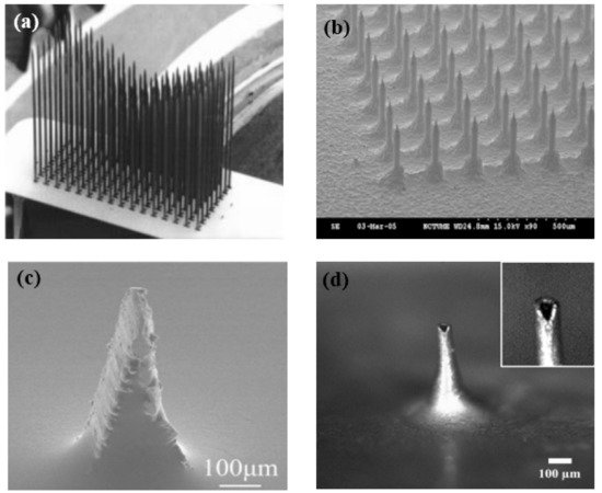
At present, a commonly used method is to combine the flexible substrates and the hard microneedle array. This method can not only ensure that the dry electrode can be close to the scalp but also allows the microneedle to penetrate the stratum corneum smoothly. The manufacturing process of microneedle array dry electrodes is becoming increasingly sophisticated, and its application in bioelectrical signal acquisition is gradually increasing, but this electrode does not have the features of being lightweight or integrated at present. In addition, the microneedle piercing the skin will still make users uncomfortable and can cause a risk of infection. As shown in Figure 6, no matter what kind of MEMS electrode, it will have a very sharp structure. With the continuous application of new materials and the constant improvement of the structure, microneedle array dry electrodes will be a good choice for BCI to collect electrical signals.
2.3.2. Non-Contacted Electrodes
Non-contacted electrodes are similar to capacitive coupling directly to the skin, which can collect bioelectric signals without touching the skin. Therefore, they are also called capacitive electrodes. Because of the non-contact performance, capacitive electrodes can overcome the defect of other electrodes that are only able to be used on hairless sites.
Non-contact electrodes contain a metal plate electrode and an active circuit. The active circuit must provide an ultra-high input impedance to avoid signal attenuation because the metal electrode can be viewed as an ultra-small capacitor. The input impedance of the amplifier should reach a high level that is four orders of magnitude greater than that of traditional wet electrodes. As a result, this places high demands on the amplifier. Lee et al. [86] designed a capacitive electrode composed of upper and lower PDMS layers, a shield plate, an electrode plate, and an adhesive PDMS layer. The electrode plate was fabricated in five layers: 30 μm polyimide, 30 nm titanium, 10 μm Cu, 30 μm Ni, and 100 nm Au. Additionally, the electrode plate was sandwiched by the PDMS layers. In the eye-closed and eye-open tests, the alpha rhythm had correlations of 0.91 and 0.83 with conventional electrodes. Liu et al. [87] designed a non-contact signal acquisition system with a diameter of 25 mm and made of a flexible printed circuit. The electrode had a two-layer structure. The bottom layer was composed of a copper-filled capacitive sensing plate and a shielding ring to avoid external interferences. The top layer was made of Cu and connected with the outer ring to improve the shielding outcomes. The electrical components were placed on the flexible printed circuit board instead of the back of the non-contact electrode to ensure optimal coupling and comfort. In general, non-contact electrodes cannot be fixed completely, which results in serious motion artifacts. In this regard, Chen et al. [88] proposed a non-contact electrode containing an active circuit and a metal plate made of Cu. The thickness and diameter were 2 mm and 20 mm, respectively. In addition, the dry electrode had an adaptive mechanical design so that the influence of motion artifacts could be reduced greatly.
In addition, some researchers have made some improvements regarding lightweight designs. Alireza et al. [89] proposed a wearable wireless device for EEG monitoring and analysis. The substrate was made of a four-layer polyimide on which the recording, quantization, and motion artifact removal circuitries were implemented. The whole wearable solution with the battery weighed 9.2 g. Due to its lightweight design, the electrode could not only be used in a laboratory but also for ambulatory EEG recording. The eight channels were sufficient to ensure that brain neural activity could be recorded with a reasonable spatial resolution.
From the above references, there is no doubt that copper is a commonly used capacitor material because of its accessibility, good molding property, and good conductivity. The electrode does not require a strict performance for materials. Compared to wet electrodes, the correlation between the two electrodes is about 90% and can meet the basic requirements for application. In addition, from Alireza’s work [89], non-contracted electrodes had the characteristic of being lightweight (9.2 g). The biggest obstacle to the development of capacitive electrodes is the motion artifact caused by the high impedance and phase shift [90].
2.3.3. Common-Contact Dry Electrodes
Common-contact dry electrodes are the most convenient type since they can directly contact the scalp, but do not penetrate the cuticle or require skin pre-treatment. The existence of hair will hinder the good contact between the electrode and the scalp, which usually requires some special structures for the electrodes to make themselves pass through the hair, such as being finger shaped. For the sake of comfort and high geometric conformity between the sensor and the irregular scalp surface, there is always a spring structure at the end of the probe to cushion the pressure on the scalp. Metal with good conductivity and biocompatibility is usually used for this special structure.
As described by Liao et al. [66] in this article, BeCu was used as the electrode column, and Au with good biocompatibility was attached to the contact area between the electrode column and the scalp. A total of 17 probes were next inserted into the thin Cu plate that served as the flexible substrate of the sensor (Figure 7a). Therefore, a good EEG signal can be obtained without skin preparation. Similarly, Liu et al. [91] proposed a spring-type electrode, in which a platinum nanoporous layer was attached to six probes of the electrode so as to decrease contact impedance and enhance conductivity (Figure 7b). Finally, the contact impedance of the dry EEG sensors, which were attached to the different sites, was below 20 kΩ. In the resting-state EEG measurement, the correlations compared to wet electrodes ranged from 0.8179 to 0.9677. Furthermore, coating conductive materials on polymer surfaces can take advantage of the softness of polymer and avoid the use of complex spring structures. Fiedler et al. [92] deposited a conductive TiN layer on a polyurethane (PU) substrate by using a multiphase DC magnetron sputtering technique (Figure 7c). Thus, the electrode was able to fit the shape of the brain and keep good contact with it. The electrode had a specific structure with 36 electrode pins on a single baseplate. Compared to wet electrodes, the variance of both signals was in the same order of magnitude. In addition, finger-shaped electrodes can be obtained by 3D printing. After the PLA plastic was printed as the mechanical structure, Ag/AgCl ink can be used as a conductive coating. Because of this special processing method, it holds substantial potential for personalized healthcare as shown in Figure 7d [93].
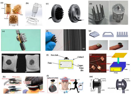
To manage thick hair, there are also brush-like electrodes similar to finger-type electrodes. They have been widely studied for some time because of their good performance. Kitoko’s research [94] provided a method using a reusable silver/silver chloride made with twelve 2 mm contact posts or bristles for EEG testing (Figure 7e). The results did not reveal any significant differences between the two electrodes in all six subjects tested compared to wet electrodes. Grozea et al. [95] proposed a bristle electrode by coating thin polymer bristles with silver particles. This kind of electrode can provide good contact with the scalp and good comfort. However, soft bristles are a double-edged sword. The conductive coatings can very easily to fall off due to the excellent flexibility of the bristles. Gao et al. [96] designed a novel passive dry pin-shaped electrode consisting of a pedestal and bristles (Figure 7f). The pedestal of the electrode was made of CNT-filled polydimethylsiloxane (PDMS-CNT), while the pins were fabricated from carbon fiber and PU with CNT doping. For the bristles, the carbon fiber would not easily break off due to the much higher modulus of elasticity than that of Ag or PDMS. Because of the small contact area of the pointed dry electrode, the subjects will feel uncomfortable. In addition, the coating is likely to fall off due to the flexibility of the probe or bristles. Other special structures that adapt to the shape of the hair and scalp can be made by 3D printing. Lee et al. [97] printed a reverse-curve-arch-shaped dry EEG electrode consisting of 92.5% Ag and 7.5% Cu (Figure 7g). The special shape can ensure the electrode overcomes the obstruction of hair effectively and the shortcomings of the limited contact area and pain induced of finger-shaped electrodes.
Besides the finger shape of pure metal, some methods are similar to conductive silica gel, in which conductive fillers are mixed into the matrix. Compared with the former, this method has a lower cost, and the comfort will be better due to the low modulus of the polymer substrate. There is no need for a complicated spring structure to adapt to the curvature of the scalp, but the flexibility of the material itself can adapt to the shape of the skull. Specifically, Krishnan et al. [98] embedded carbon fiber into silicone foam owing to the biocompatibility and chemical inertness, which are appealing for use in EEG systems. Considering the conductivity, hardness, flexibility, and ease of fabrication, Chen et al. [99] mixed an ethylene propylene diene monomer matrix with different additives such as carbon, stainless fibers, and carbon nanotubes. The skin electrodes’ impedance for 50% carbon content was about 10-fold higher than that of conventional wet electrodes, and the polymer electrodes containing 45% carbon had the best compromise between electrical and mechanical properties. The polymer electrodes showed nearly the same correlation and coherence as the wet electrode signals, but due to the high impedance, a lower SNR was obtained.
In addition, there are some new textile EEG electrodes, also named “textrodes”, that have gradually proved their feasibility in EEG acquisition due to their flexibility, stackability, and washability [61]. The initial use of textile electrodes was for neonatal monitoring systems. For long-term EEG detection in newborns, the electrodes should not stimulate the sensitive skin of infants. However, any type of the former electrodes will inevitably bring about a pressure point. Therefore, textile electrodes came into being. These were originally used with a conductive paste, which suggests that they do not deviate from the category of “wet electrodes”. There are two electrodes proposed. The first one was knitted using a yarn containing 78% polyamide and 22% elastomer. The fabric was plated with 99% pure silver. The second one was made of 15% nylon, 30% silver-plated conductive fibers, 20% Spandex, and 35% polypropylene. The material was knitted and is similar to a terrycloth. However, the author did not consider the performance of the dry electrode after the conductive paste had dried [100]. Similarly, Kumar et al. [101] carried out the same research. Polyethylene terephthalate (PET) fabric was used as a substrate with a copper coating on it. The fabric layer encloses foam to ensure comfort for users. The SEM images show a very uniform deposition of copper on the fabric leading to good conductivity. However, electroless copper plating was carried out through multistep processes, including pre-treatment, sensitization, activation, electroless copper plating, post-treatment to stop copper reduction, rinsing, and drying. Lin et al. [102] proposed a dry foam-based electrode for long-term EEG measurement by selecting urethane material as the matrix covered with 0.2 mm thick taffeta material made using electrically conductive polymer fabric. Finally, all surfaces were coated with Ni/Cu to establish electrical contact. The foam structure allowed high geometric conformity between the electrode and irregular scalp surfaces to maintain low skin–electrode interface impedance. Silver and copper are very popular among coating materials. In addition to pure metal particle coatings (Figure 7h–j), there are also some ideas using graphene coating [103] for ECG and polyaniline PANI [104].
With the development of integration, there are still some dry electrodes only focusing on the hairless area, which are more lightweight. For example, Li coated Ag/AgCl onto a polyacetylimide substrate by screen printing [105]. Jiang et al. [106] used the electrically conductive composite of Ag flakes and PDMS on the silicon substrate. This method of conductive material attached to the thin flexible substrate is usually used in the hair-free area of the forehead, which can achieve the same performance as that of wet electrodes. With the development of the production process, some circuits including amplifiers and capacitors can be integrated into the substrate. At present, researchers can even combine other functions with EEG electrodes. For example, Lee et al. [107] mixed silver nanowire and carbon nanotubes into PDMS (polydimethylsiloxane), forming an elastomeric conductive electrode that also acted as an earphone (Figure 7l). Kappel et al. [108] adopted a thermal iridium oxide film (TIROF) formed on an etched Ti surface as an electrode, and inserted it into holes in a soft earpiece as shown in Figure 7m.
Flexible and composite materials are a current development trend in dry electrodes. These properties can maintain the electrodes’ high geometric conformity with the irregular scalp surface and are more portable. By this method, EEG acquisition and other functions can be integrated, which can also release the potential of BCI application as much as possible.
2.4. Semi-Dry Electrodes
Recently, many researches have focused on the combination of dry electrodes and wet electrodes. Wet electrodes need long-term preparation and even hair-removal treatment before EEG recording and can cause discomfort during the measurement. For dry electrodes, the electrolyte between the scalp and electrodes is only provided by sweat and moisture in the air. The lack of electrolytes leads to a high impedance, so there is still a gap in the signal quality between dry electrodes and wet electrodes. A semi-dry electrode overcomes the shortcomings of a dry electrode and a wet electrode. The electrode itself contains electrolytes and gradually releases them during use. The electrolytes permeate the stratum corneum and reduce impedance. Semi-dry electrodes avoid long preparation times and high impedance.
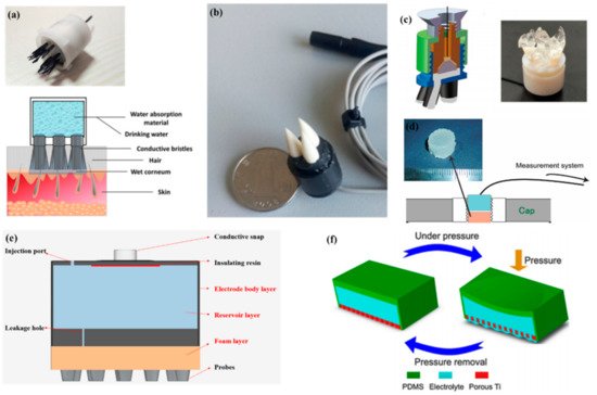
In 2013, Mota et al. [109] first proposed the concept of semi-dry electrodes. The polymer-based electrode can release a small amount of a moisturizing agent (30 μL) from a reservoir inside the electrode. Thermoset PU coated with an Ag/AgCl chemically deposited layer was chosen to prototype the electrode concept. The experiments showed that the signal quality of semi-dry electrodes is comparable to that of wet electrodes. However, there are still some problems with them. Semi-dry electrodes need to apply pressure to promote the release of electrolyte liquid, and it is difficult for each electrode to achieve uniform pressure. Thus, the uncontrollable release of electrolyte liquid will result in an unstable signal. Like bristle electrodes, the Ag/AgCl layer of semi-dry electrodes can easily to fall off due to the constant pressure. Li et al. [110] proposed a ceramic-based semi-dry electrode and solved this problem. The electrode was composed of five porous Al2O3 ceramic pillars, a built-in reservoir, and a sintered Ag/AgCl electrode. Due to the capillary of the porous ceramics, the saline solution can be released continuously at the rate of 10~20 μL/h, which leads to a more stable property.
To make the electrolytes more evenly distributed in each electrode, Hua et al. [111] designed a flexible, multi-layer, semi-dry electrode consisting of three layers: the electrode body layer, the reservoir layer, and the foam layer. At the bottom of the reservoir, there are five leakage holes which are 0.25 mm in diameter so that the electrolyte solution can flow into the foam. The foam layer stores the electrolyte so it does not rapidly drain. The electrode body layer was made of flexible conductive composite materials with PDMS as the distributed matrix and silver nanoparticles as the conductive filler. The conductive foam was coated with Cu and Ni nanoparticles to obtain good electrical conductivity. The structure was suitable for EEG monitoring in some hairy areas, and the correlation with wet electrode signals could reach about 94.25% and 90.65%, respectively, in static and dynamic EEG monitoring. In a recent study, the combination of a bristle electrode and a semi-dry electrode was carried out by Gao et al. The bristle was fabricated using a hydrophilic material so that water could spread from the roots to the top [112]. Similarly, Xing et al. [113] proposed a micro-seepage electrode with five components. There are flexible and elastic brush pen-like tips made of PU that pass through the hair and contact the scalp. After contact with the scalp and with little pressure, the tip can transport electrolytes that were stored in a cavity made of a polymer sponge. Furthermore, this study investigated the contact impedance of the electrode concerning contact pressure on the occipital area. Under different pressures, the contact impedances ranged from 25 kΩ to 8 kΩ (@ 10 Hz) and from 0.3 N to 10 N.
The abovementioned semi-dry electrodes were made using some special structures, but they all had some common problems including complex molding processes and large volumes. Besides this method, there are some other approaches such as conductive sponges or conductive gels. To reduce the volume of an electrode, Peng et al. [114] proposed a novel electrode consisting of a thin piece of porous Ti as a signal and a reservoir made by PDMS for storage of the electrolytes. Resulting from the excellent mechanical performance and biocompatibility, porous Ti is widely used in medical fields. The electrode was the same size as a coin. Lin et al. [115] coated silver nanowires on a melamine sponge with a PVB solution as an accessory ingredient for the adhesion between the melamine sponge and Ag nanowires and the protection of the exposed Ag nanowires. Besides low contact impedance (<10 kΩ) and a high BCI accuracy of the new electrode (86%) compared to that of wet electrodes (88%), the flexible sponge framework and self-locking Ag nanowires combined to give the new electrode remarkable mechanical stability. The method of preparing a conductive sponge is similar to that of the “textrode” mentioned above, in which the conductive material is coated on a soft substrate, but the sponge has better water storage performance, so the conductive sponge can realize the dual functions of water storage and conductivity. In addition, the soft structure of the sponge can give electrodes better geometric conformity with the scalp. Therefore, it is a very promising way for sponge structures to be coated with conductive materials.
The above semi-dry electrodes all had a reservoir to store the electrolyte solution or water. Another method for semi-dry electrodes is to store as many electrolytes as possible in the electrode body. Toyama et al. [116] proposed a solid-gel electrode that was made of CMC sodium salt, calcium chloride dihydrate, glycerol, and pure water. CaCl2 and glycerol are water-absorbing materials that provide a superior wettability of the solid gel. For the electrodes to pass through the hair, Qin et al. [65] proposed a finger-shaped electrode composed of an ionic hydrogel, which was a polyacrylamide (PAAm) hydrogel containing NaCl. The contact impedance was far from that of the wet electrodes (17.4 kΩ to 4.2 kΩ). However, the soft ionic hydrogel-based electrodes had a similar performance to that of the conventional wet gel electrodes in terms of the short-circuit noise, EEG signal quality, and the SSVEP user-centered test.
A common feature of semi-dry electrodes is that they reduce skin contact impedance through the storage and release of electrolytes as shown in Figure 8. Since they have only recently been developed, there is still much room for improvement, such as how to ensure that the electrodes can easily pass through the hair and release electrolytes, but still maintain a good sense of comfort.
This entry is adapted from the peer-reviewed paper 10.3390/mi12121521
This entry is offline, you can click here to edit this entry!