Your browser does not fully support modern features. Please upgrade for a smoother experience.
Please note this is an old version of this entry, which may differ significantly from the current revision.
Subjects:
Surgery
Finally, EPPOCRATIS is an in-house (point-of-care) process that can be completed in 24-48 hours, allowing precise and expedited care of facial trauma patients. Bypassing outsourcing to third-party companies allows for the implementation of VSP/3DP in the acute trauma setting during the same hospitalization of trauma patients. Potential challenges with building an in-house VSP/3DP also exist including cost and personnel. However, as the technology becomes more readily available and cheaper, it will become more utilized in large volume centers.
- point of care
- virtual planning
- three-dimensional printing
- facial trauma
1. Introduction
Virtual surgical planning (VSP) and three-dimensional printing (3DP) have become widely used in planning and execution of craniomaxillofacial surgery [1,2]. Previous studies reported successful use of patient-specific 3DP models and surgical guides in the operating room [2,3,4,5]. However, the process of VSP and 3DP continues to be time-consuming due to the sourcing to third-party companies and lack of in-house computer-aided design and manufacturing (CAD/CAM) processes [2,6]. The integration of VSP and 3DP at the point-of-care (POC) is paramount for a timely and efficient use of the technology in the management of acute craniomaxillofacial trauma.
2. EPPOCRATIS Process
EPPOCRATIS consists of a total of seven stages which are as follows: (1) computed-tomography (CT) scan/data acquisition, (2) segmentation, (3) virtual surgical planning (VSP), 94) 3-Dimensional Printing (3DP), (5) Post-processing, (6) Plate Bending and (7) surgery (Video S1, Supplementary Materials). The entire process can be completed in 24-48 h from CT Scan/Data acquisition to surgery. Most of this time in 3DP model creation involves the printing and post-processing stages.
2.1. CT Scan/Data Acquisition
CT images of the facial bones and head are obtained using the standard thin slice, 0.5–0.75 mm, trauma protocol thickness. DICOM images are then transferred to the anatomic modeling unit, which is an in-house point of care manufacturing facility.
2.2. Segmentation
The CT images are imported into an advanced image processing software, Mimics 23.0 (Materialise, Leuven, Belgium). The mandible and skull are segmented, a process in which borders of anatomic regions within the scan are defined from 2D greyscale images to create a 3D model. Each individual fracture fragment that will be moved to a normalized position must be segmented as a unique object. Once the segmentation is complete, the segmented file is transferred to a medical CAD software program 3-Matic 15.0 (Materialise, Leuven, Belgium) for 3D file error fixing, optimization, and 3DP file export (Video S1, Supplementary Materials). This stage takes 30–35 min including the time it takes for a radiologist to perform quality control and look at the contours of the 3D file back on the axial images to assure the accuracy of segmentation.
2.3. VSP
Once the 3D file is created, a VSP session is performed by the biomedical engineers and the plastic surgeon. In this stage, the virtual reduction of fractures to “normalized anatomy” is ensured by moving the fragments back to their original position using mirror imaging if the contralateral side is normal, using standard anatomic landmarks, or 3D files from age-matched normal compares. The software’s tools such as “transparency” and “mirroring” are utilized to achieve virtual anatomic reduction of the fractures in three planes. The “overlap” tool enables the user to evaluate the reduction clearly by overlapping the post-traumatic and post-VSP 3D-CT images (Video S1, Supplementary Materials). For the occlusal fractures, the dental arch alignment is designed to achieve the optimal anatomical alignment, although minor discrepancies with the true occlusion may still occur and should be corrected intraoperatively. The engineer will spend an average of 20 min on CAD file fixing, mirror imaging, and preparing for printing.
2.4. 3D Printing
Following the virtual reduction of the fractures to the normalized anatomy, the 3D image is exported as a .STL (Standard Tessellation Language) file. This file contains the 3D data for “the patient-specific virtually reduced craniofacial model”. The virtual model is then put through slicing software so the 3D object can be manufactured 1 slice at a time by the 3D printer. For full-color non-sterilizable printing that can be used for preoperative planning and education, three printer technologies are available, including binder jetting, material jetting, and sheet lamination. If sterilizable biocompatible 3D printed models are needed for plate bending and intraoperative use, then powder bed fusion and vat polymerization can be used. In the facility, the sterilizable 3DP model is made using vat photopolymerization on a Form3B Form Labs stereolithography (SLA) 3D printer (Formlabs, Boston, MA, USA) using Formlabs Surgical Resin. The 3DP objects made with this resin material have been independently verified by the institution to be sterilizable in the autoclave, biocompatible, and not cytotoxic. The printing stage varies from 2 h to 13 h based on technology and resolution of printer and print technology. (Figure 1).
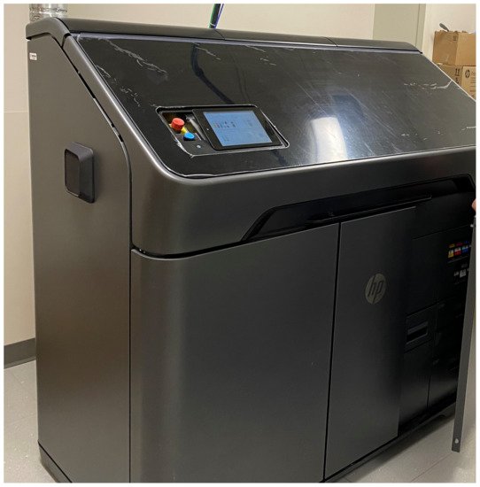
Figure 1. Hewlett-Packard (HP, Palo Alto, CA, USA) 3D Printer.
2.5. Post-Processing
After printing, the 3DP model undergoes a post-processing process by the AMU staff prior to being delivered to the surgeon. Depending on the technology used for printing the post-processing step to remove support material can include removing excess powder, bead blasting, soaking in lye baths and water jetting, soaking the model in color binding agents and cyanoacrylate, or photocuring and removal of support material. For Formlabs Form 3B SLA printers using surgical resin, the steps include alcohol washing, photocuring, and finally, support strut removal. Additionally, a quality control step is added to assure anatomic accuracy of the 3D printed model to the 3D printed CAD file. This included visual inspection, surface metrology, and caliper measurements. The post-processing stage takes 15 min to 6 h, depending on the model and material printed.
2.6. Plate Bending
The virtually reduced 3DP model is then delivered to the plastic surgeon for bending the fixation plates in accordance with the 3DP model’s normalized form and shape (Figure 2). This serves as a valuable hands-on training opportunity for the residents outside the operating room pressure (Figure 3) and reduces costly intraoperative time. The prebent plates are then sterilized for intraoperative use. The plate bending time is dependent on the complexity of the case, taking approximately 1–2 h.
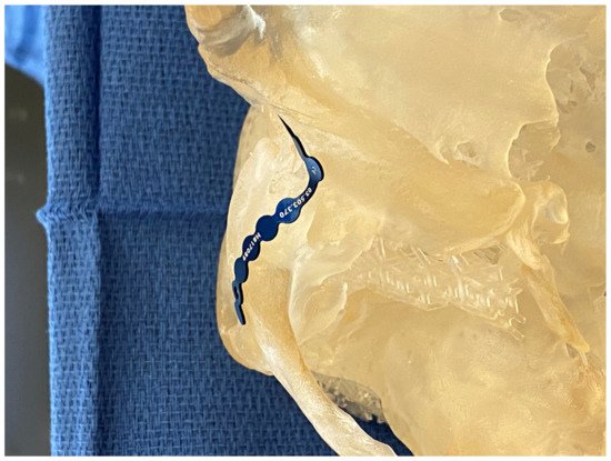
Figure 2. Template bending in preparation for plate bending on a patient-specific high-fidelity 3DP model.
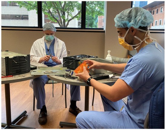
Figure 3. Using the high fidelity 3DP model preoperatively to teach trainees how to bend plates and review pertinent anatomy and surgical plan.
2.7. Surgery
The sterilized prebent plates are used in the operating room as guides. Instead of fracture reduction first, then plate adaptation, the plate serves as a surgical guide for fracture reduction based on the perfected anatomy in the 3DP model. This adds another layer of accuracy to fracture reduction, especially in extensive panfacial trauma. Furthermore, the intraoperative time is shortened with EPPOCRATIS. Perioperative 3DP models of a patient during the EPPOCRATIS process are shown in Figure 4.
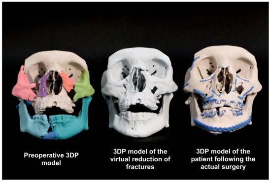
Figure 4. Patient-specific high-fidelity 3DP models from various stages of EPPOCRATIS.
This entry is adapted from the peer-reviewed paper 10.3390/jcm10235640
This entry is offline, you can click here to edit this entry!