As one of the major causes of concrete deterioration, the carbonation of concrete has been widely investigated over recent decades. In recent years, the effect of mechanical load on carbonation has started to attract more attention. The load-induced variations in crack pattern and pore structure have a significant influence on CO2 transport which determines the carbonation rate.
- concrete
- carbonation
- mechanical load
- crack
- loading frame
1. Introduction
Carbonation of concrete is one of the major causes of reinforced concrete deterioration. Concrete is inevitably porous. The pores and microcracks exist both at the inside and on the surface of concrete, which allows the penetration of CO 2 when the surface of concrete is exposed to the atmosphere. In the presence of moisture, CO 2 will dissolve in the pore solution and form HCO 3− and CO 32− ions, and consequently cause carbonation of hydration products of concrete such as portlandite (Ca(OH) 2) [1], calcium silicate hydrates (C-S-H) [2][3][4], and ettringite [5][6], even of unhydrated cement particles [7][8] such as tricalcium silicate (C 3S) and dicalcium silicate (C 2S). In the carbonation process, different polymorphs of CaCO 3 are formed, including calcite, vaterite, and aragonite. At high alkalinity, the Ca 2+ mainly originates from the dissolution of portlandite. With the continuous consumption of Ca(OH) 2, the alkalinity of concrete decreases gradually. When the carbonation front reaches the reinforcement, further carbonation will cause the depassivation of steel reinforcement. From then on, there is an onset of active corrosion, which shortens the service life of reinforced concrete structures. Therefore, as a critical issue, carbonation of concrete has been widely investigated [9][10][11][12].
The carbonation process is dominated by several factors including material composition, carbonation condition, and curing. These key factors determine the carbonation rate and carbonation products. Therefore, numerous efforts have been made to understand the CO 2 transport and reaction mechanisms [13][14][15]. Whereas, only limited research exists about the carbonation of concrete under mechanical load. Reinforced concrete is designed to bear mechanical load which usually causes variation in porosity and crack patterns. According to Eurocode 2 [16], the design concrete strength is 67% of characteristic strength at most. In some cases, the limitation of stress in concrete is even lower. For example, considering creep, the stress limitation is 0.45 of the breaking load. Though reinforced concrete structures have been calculated to endure service loads without critical impacts on their mechanical properties over the service life, loads may make concrete more vulnerable to the ingress of water, CO 2, chloride, and other agents. Therefore, when investigating the deterioration process of reinforced concrete under environmental effects, the effect of mechanical load should not be ignored. For decades, researchers have gained a preliminary understanding of the effect of precracking on the carbonation of concrete [17][18][19]. The issue of carbonation under sustained load is more realistic and should therefore receive considerable critical attention. Service life prediction models can be optimized using the output (e.g., critical threshold load levels) of accelerated carbonation tests under sustained load.
2. Carbonation in Cracked and Load-Damaged Concrete
Essentially, when investigating the effect of load on carbonation, the most critical factor is the variation in crack and pore structure caused by the application of load. With different types and levels of mechanical load applied, the cracks vary in number, length, width, and pattern. Consequently, the process of CO 2 transport is changed to some extent. Based on the mechanisms of concrete carbonation, the CO 2 transport and carbonation affect each other mutually. On the one hand, better CO 2 transport properties result in faster carbonation. On the other hand, the formation of carbonation products of portlandite, including calcite, aragonite, and vaterite, results in a volume increase of 11.2%, 2.9%, and 18.7%, respectively [20]. The produced water and precipitated CaCO 3 in Portland cement concrete will fill the pores and cracks and therefore lower the CO 2 transport properties in turn.
Cracks are very common in concrete. Even without external load, the heat of hydration, autogenous and drying shrinkage, and improper curing may cause cracks in concrete surfaces. In reinforced concrete beams, concrete in the flexural tension zone will be cracked once in service. These cracks, as flow channels for CO 2, may facilitate direct exposure of the rebars to CO 2. Hence, the carbonation takes place at the interface between steel rebar and concrete even though only limited carbonation occurs at the concrete cover [17][21], which means the concrete cover no longer has an effect at the location of the crack. However, only wide enough cracks, acting as additional exposure surfaces to CO 2, will have a great impact on carbonation. While microcracks would only accelerate the carbonation slightly. Small cracks may close again as a result of carbonation-induced autogenous healing [22]. To gain a better understanding of the latter aspect, some researchers investigated the carbonation behavior of concrete in which cracks with certain geometries were induced deliberately. In some cases, a lower crack width threshold was found, below which CO 2 transport is not increased in comparison with uncracked material. On the other hand, an upper crack width threshold may occur, above which the carbonation rate remains stable independent of the crack width. The results obtained in the literature are summarized in Table 1 .
Table 1. Overview of literature evaluating effect of cracks on carbonation.
| Crack Type | Crack Inducing Method | CO2 Level | Crack Pattern | Lower/Upper Crack Width Threshold (μm) | Reference |
|---|---|---|---|---|---|
| Artificial crack | Embedding of thin plates | 20% | 100, 200, 300, 500, 620 μm in width and 20 mm in depth | −/100 | [23] |
| Artificial crack | Embedding of thin plates | 10% | 200, 300, 500 μm in width and 5, 10 mm in depth | * | [24] |
| Artificial crack | Embedding of thin plates | 1% | 100, 200, 300 μm in width and 30 mm in depth | −/100 | [25] |
| Realistic crack | Splitting | 1% | 100, 200, 300 μm in width | * | [25] |
| Artificial crack | Sawed and smoothed | 50% | 10–150 μm in width | * | [26] |
| Realistic crack | Expansive core | 50% | 9–400 μm in width | 9/60 | [26] |
| Artificial crack | Embedding of thin plates | 3% | 100, 200, 300 μm in width and 10 mm in depth | −/100 | [27] |
| Realistic crack | Bending | 3% | 100, 150 μm in width | * | [27] |
| Realistic crack | Bending | 5% | 50–350 μm in width | * | [28] |
| Realistic crack | Bending | Natural | 80, 500, 700 μm in width | * | [29] |
| Realistic crack | Bending | 2% | 50, 100, 150, 200, 300 μm in width | * | [30] |
* the carbonation depth keeps increasing with the increase in crack width under the given condition.
Artificial cracks are induced by positioning a thin plate inside the specimens during casting and removing this plate after hardening of the specimens. Via this method, standardized cracks without tortuosity are created. The crack depth and crack width can be easily controlled that way. Though the crack width determines the amount of CO 2 molecules entering into the crack per unit of time, the following CO 2 transport along the crack path also depends on the carbonation at the crack walls which consumes CO 2. If the CO 2 transport into the crack is slow, there can be a concentration gradient of CO 2 along the crack depth. Consequently, the carbonation rate is the highest at the outer surface, followed by the crack surface and the lowest at the crack tip [23]. Different authors observed an upper crack width threshold of 100 μm at CO 2 levels of 1% [25], 3% [27], and 20% [23]. The carbonation rate remains stable as the crack width increases above this value. At a CO 2 level of 50%, Alahmad found that the carbonation depth measured at an artificial crack surface with a crack width of 10 μm is already higher than the carbonation depth in an uncracked region of the concrete surface [26], indicating a lower crack width threshold below 10 µm. A possible explanation is that a much higher CO 2 concentration causes adequate CO 2 supply even in very fine cracks. Besides, an empirical formula was developed by De Schutter to quantify the effect of crack depth and width on the carbonation [24].
However, real cracks in concrete are much more complicated than artificial cracks. The differences between artificial cracks and realistic cracks should be carefully considered. For instance, the surfaces of artificial cracks are smoother and higher in cement content (the so-called “wall effect”) [24]. Moreover, the width of realistic cracks becomes gradually lower along the crack path. The interlocking and tortuosity of realistic cracks will hinder the transport of CO 2. Generally, artificial cracks cause a higher carbonation depth. So, the effect of realistic cracks should also be investigated. In some studies, realistic cracks are induced through the application of flexural or splitting load while the crack width is being monitored. Contrary to artificial cracks, it is found that the carbonation rate still increases when the realistic crack width exceeds 100 μm (CO 2 level: 1% and 5%) [25][28]. Under a much higher CO 2 level of 50%, Alahmad [26] found that carbonation rate perpendicular to a realistic crack wall is similar to that at the concrete surface when the crack width is higher than 60 μm, and that CO 2 transport appears to stop for crack width of 9 μm or less.
3. Carbonation of Concrete under Sustained Load
In view of the differences in crack pattern and pore structure between the loaded and unloaded situation, more researchers have started to investigate the effect of sustained load on the carbonation of concrete recently, not merely precracking and stress damage. Though the studies on carbonation under sustained load are more realistic, it should be noted that creep of concrete can have a great influence in case of accelerated carbonation in a laboratory environment. Creep of concrete is noticeably higher at early age. Therefore, if the specimens were put into a CO 2 chamber right after the load application, the substantially higher creep at early stage can influence the CO 2 transport. Further studies should pay attention to the early-stage creep in combination with accelerated carbonation in a CO 2 chamber.
The effect of applied compressive load on a concrete structure highly depends on the stress level. Lim [31] investigated the crack patterns under different stress levels through microscopy observation. According to his research on concrete crack length after compressive load, bond cracks occur at the aggregate–mortar interface when the stress level is above 0.3 times the failure stress and the total crack length increases significantly when the stress level exceeds 0.5. Notable isolated mortar cracks occur at a stress level of 0.7 and interconnect with bond cracks at the 0.9 stress level. Though the crack opening displacement reduces after the load is completely removed [32], it is helpful to understand the transport properties of concrete under sustained compressive load.
On the contrary, a uniaxial tensile load only results in the generation and growth of microcracks perpendicular to the direction of the tensile load and makes concrete less dense. Hence, uniaxial tensile load always leads to an increase in gas permeability [33] and carbonation rate [34]. Recycled aggregate concrete is more sensitive to tensile load as opposed to compressive load because of larger microstructural changes under tensile load [35]. Besides, though different patterns of cracks are induced, a splitting tensile load has a similar effect on concrete carbonation.
Considering that few reinforced concrete structures are serving under uniaxial tensile stress in practice, three-point bending and four-point bending modes are used in many studies for a better understanding of concrete carbonation in practice. Besides, the loading frame for applying a bending load is usually smaller than a loading frame for applying uniaxial tensile loads, and can easily be put in a CO 2 chamber.
4. Test Methods for Carbonation of Concrete under Sustained Load
The sustained loads are applied and maintained with loading frames which are similar to the post-tensioning system for prestressed concrete. Usually, threaded bar tendons which are put inside or outside of the specimens are used so that both tensile and compressive stress can be provided. When investigating the effect of load on concrete under different environmental conditions other than carbonation, the loading frame for applying external mechanical load is mostly the same. Thus, the loading frames for environmental action other than carbonation are also included in the following discussion. For applying different types of loads including uniaxial compressive load [36][37], uniaxial tensile load [38][39], three-point bending load [40], and four-point bending load [41][42] by use of external bar tendons, several loading frames have been designed. Typical loading frames are shown in Figure 1 a–c. Such a loading frame with external threaded bar tendons can provide a more even and accurate load through adjusting four nuts. A loading frame which simulates a corbel and applies flexural loads was reported [43].
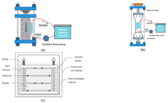
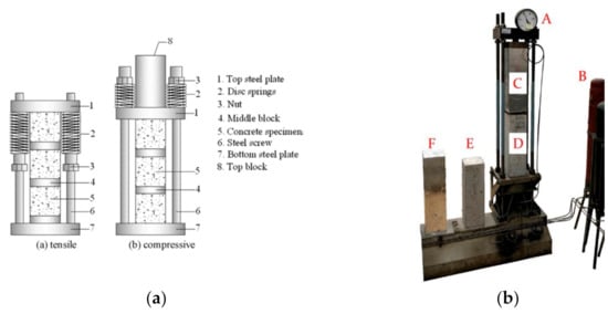
Based on the loading setups mentioned above, some researchers added springs on the bar tendons, as shown in Figure 1 c. In this case, the load is transmitted through the springs and not merely through the bar tendons. So, when inevitable stress losses occur, the applied external load will not decrease too much because of the buffering effect of the spring. Nevertheless, to provide large enough load within a slight strain, very strong springs are required, which will greatly increase the total weight and size of the setup. If the springs are not strong enough, the applied stress cannot reach the designed stress level [36], especially for compressive stress. In order to keep the total weight as light as possible and allow for a compact design, disc springs (Belleville washer), which can support very large loads with a small installation space, are used [44], as shown in Figure 2 a. Moreover, if the CO 2 chamber is large enough, the creep setup is certainly an ideal option for applying uniaxial compressive load. For example, as shown in Figure 2 b, the external load is provided by the gas pressure of the compressed air in a gas bottle. The load is more stable because the decrease in gas volume caused by the slight deformation of concrete has a smaller effect on the load level.
For loading frames with external bar tendons, hydraulics and torque wrenches [30] can be used to apply load. Applying load through hydraulics is more accurate but the operator should pay attention to the stress losses. If the load applied by the hydraulics is kept at a fixed value when tightening the nuts, the load carried by the concrete specimen can drop greatly after the hydraulics is removed because of the bolts loosening and the elastic deformation of the loading frame. If the hydraulics is kept stationary when tightening the nuts, the load applied by the hydraulic machine decreases gradually, and the load on the concrete specimens reaches the design value when the load applied by the hydraulics drops to zero. By this means, the stress loss occurring right after the removal of the hydraulics can be avoided because the loading frame, including the bolts and nuts, is already loaded. However, the nuts have to be tightened by wrench manually, which may be infeasible if a compressive load is to be applied. The load can also be applied by torque wrench but is less accurate. The reason is that the measured torque is derived from the friction between the nut and screw which highly depends on the nut and screw specifications and even whether they are free of rust and lubricated or not. Yet, it is still a simple way to apply a relatively low load. Moreover, the operator can apply the load with a wrench manually by checking the resulting strain when the strain gauges are glued on the specimens.
During carbonation, the load maintained by the loading frame always drops with time. This phenomenon of stress relaxation is inevitably caused by shrinkage and creep of concrete and bolt loosening. When the designed stress level is relatively low, regularly releasing the load followed by reloading would be a solution to the problem. However, it is reported that, when the load level is over 54% of the failure load, the apparent Poisson’s ratio starts to change clearly, which means that irreversible plastic deformation occurs [46]. In this case, reloading will result in unexpected changes in the crack pattern. Besides, some researchers applied excessive load on concrete specimens to counter the stress loss, which is similar to the procedure for prestressed concrete [47][48]. In the case of prestressed concrete, usually slightly excessive load (3–5% of designed load) is applied to ensure the structural safety. However, this can only keep the average stress near or above the design value but not mitigate the effect of shrinkage and creep. Since there is no requirement for structural safety in a loading setup for laboratory tests, more measures are needed to avoid too much stress loss during the carbonation. For instance, as mentioned before, the stress relaxation during the long-term carbonation experiment can be alleviated by the designed springs. In addition, the load can be compensated by regularly tightening the nuts when the load is monitored by a load cell. Since the load cell is costly and will make the design of the loading frame more complicated, tightening the nuts to keep the length of springs can be an alternative.
This entry is adapted from the peer-reviewed paper 10.3390/ma14164407
References
- García-González, C.A.; Hidalgo, A.; Andrade, C.; Alonso, M.C.; Fraile, J.; Lopez-Periago, A.M.; Domingo, C. Modification of composition and microstructure of portland cement pastes as a result of natural and supercritical carbonation procedures. Ind. Eng. Chem. Res. 2006, 45, 4985–4992.
- Morandeau, A.E.; White, C.E. In situ X-ray pair distribution function analysis of accelerated carbonation of a synthetic calcium–silicate–hydrate gel. J. Mater. Chem. A 2015, 3, 8597–8605.
- Morandeau, A.; Thiéry, M.; Dangla, P. Investigation of the carbonation mechanism of CH and C-S-H in terms of kinetics, microstructure changes and moisture properties. Cem. Concr. Res. 2014, 56, 153–170.
- Black, L.; Breen, C.; Yarwood, J.; Garbev, K.; Stemmermann, P.; Gasharova, B. Structural features of C?S?H(I) and its carbonation in air?A raman spectroscopic study. Part II: Carbonated phases. J. Am. Ceram. Soc. 2007, 90, 908–917.
- Fernández-Carrasco, L.; Torrens-Martin, D.; Martinez-Ramirez, S. Carbonation of ternary building cementing materials. Cem. Concr. Compos. 2012, 34, 1180–1186.
- Xiantuo, C.; Ruizhen, Z.; Xiaorong, C. Kinetic study of ettringite carbonation reaction. Cem. Concr. Res. 1994, 24, 1383–1389.
- De Han, J.; Pan, G.; Sun, W.; Wang, C.; Cui, D. Application of nanoindentation to investigate chemomechanical properties change of cement paste in the carbonation reaction. Sci. China Technol. Sci. 2011, 55, 616–622.
- Peter, M.; Muntean, A.; Meier, S.; Böhm, M. Competition of several carbonation reactions in concrete: A parametric study. Cem. Concr. Res. 2008, 38, 1385–1393.
- Šavija, B.; Luković, M. Carbonation of cement paste: Understanding, challenges, and opportunities. Constr. Build. Mater. 2016, 117, 285–301.
- Ekolu, S.O. A review on effects of curing, sheltering, and CO2 concentration upon natural carbonation of concrete. Constr. Build. Mater. 2016, 127, 306–320.
- Chang, C.-F.; Chen, J.-W. The experimental investigation of concrete carbonation depth. Cem. Concr. Res. 2006, 36, 1760–1767.
- Marques, P.F.; Chastre, C.; Nunes, Â. Carbonation service life modelling of RC structures for concrete with Portland and blended cements. Cem. Concr. Compos. 2013, 37, 171–184.
- Salvoldi, B.G.; Beushausen, H.; Alexander, M.G. Oxygen permeability of concrete and its relation to carbonation. Constr. Build. Mater. 2015, 85, 30–37.
- Houst, Y.F.; Wittmann, F.H. Influence of porosity and water content on the diffusivity of CO2 and O2 through hydrated cement paste. Cem. Concr. Res. 1994, 24, 1165–1176.
- Sanjuán, M.A.; Andrade, C.; Cheyrezy, M. Concrete carbonation tests in natural and accelerated conditions. Adv. Cem. Res. 2003, 15, 171–180.
- Eurocode 2. Design of Concrete Structures; British Standards Institution: London, UK, 2008.
- François, R.; Maso, J. Effect of damage in reinforced concrete on carbonation or chloride penetration. Cem. Concr. Res. 1988, 18, 961–970.
- Liang, M.-T.; Qu, W.-J.; Liao, Y.-S. A study on carbonation in concrete structures at existing cracks. J. Chin. Inst. Eng. 2000, 23, 143–153.
- Song, H.-W.; Kwon, S.-J.; Byun, K.-J.; Park, C.-K. Predicting carbonation in early-aged cracked concrete. Cem. Concr. Res. 2006, 36, 979–989.
- Arandigoyen, M.; Bicer-Simsir, B.; Alvarez, J.; Lange, D. Variation of microstructure with carbonation in lime and blended pastes. Appl. Surf. Sci. 2006, 252, 7562–7571.
- Hiep Dang, V.; François, R.; L’Hostis, V. Effects of pre-cracks on both initiation and propagation of re-bar corrosion in pure carbon dioxide. EPJ Web Conf. 2013, 56, 6006.
- Van Tittelboom, K.; de Belie, N. Self-healing in cementitious materials—A review. Materials 2013, 6, 2182–2217.
- Zhang, S.P.; Zong, L.; Dong, L.F.; Zhang, W. Influence of cracking on carbonation of cement-based materials. Adv. Mater. Res. 2011, 261-263, 84–88.
- De Schutter, G. Quantification of the influence of cracks in concrete structures on carbonation and chloride penetration. Mag. Concr. Res. 1999, 51, 427–435.
- Van Mullem, T.; de Meyst, L.; Handoyo, J.P.; Caspeele, R.; de Belie, N.; Heede, P.V.D. Influence of crack geometry and crack width on carbonation of High-Volume Fly Ash (HVFA) mortar. In Proceedings of the International RILEM Conference on Ambitioning a Sustainable Future for Built Environment: Comprehensive Strategies for Unprecedented Challenges, Guimarães, Portugal, 10–14 March 2020.
- Alahmad, S.; Toumi, A.; Verdier, J.; Francois, R. Effect of crack opening on carbon dioxide penetration in cracked mortar samples. Mater. Struct. 2008, 42, 559–566.
- Bogas, J.; Carriço, A.; Pontes, J. Influence of cracking on the capillary absorption and carbonation of structural lightweight aggregate concrete. Cem. Concr. Compos. 2019, 104.
- Al-Ameeri, A.; Rafiq, M.I.; Tsioulou, O. Influence of cracks on the carbonation resistance of concrete structures. In Proceedings of the 6th International Conference on Durability of Concrete Structures (ICDCS 2018), Leeds, UK, 18–20 July 2020; pp. 1–8.
- Torres, J.; Andrade, C. Influence of crack width on long term degradation of concrete Structures. In Durability of Reinforced Concrete from Composition to Protection; Springer: Cham, Switzerland, 2015; pp. 87–98.
- Carević, V.; Ignjatović, I. Influence of loading cracks on the carbonation resistance of RC elements. Constr. Build. Mater. 2019, 227, 116583.
- Lim, C.; Gowripalan, N.; Sirivivatnanon, V. Microcracking and chloride permeability of concrete under uniaxial compression. Cem. Concr. Compos. 2000, 22, 353–360.
- Wang, K.; Jansen, D.C.; Shah, S.P.; Karr, A.F. Permeability study of cracked concrete. Cem. Concr. Res. 1997, 27, 381–393.
- Tang, G.; Yao, Y.; Wang, L.; Cui, S.; Cao, Y. Relation of Damage Variable and Gas Permeability Coefficient of Concrete under Stress. J. Wuhan Univ. Technol. Mater. Sci. Ed. 2018, 33, 1481–1485.
- Liu, X. Study on Carbonization and Chlorine Ion Penetration Corrosion Regularity of Coastal Concrete Bridge under Load in Service; Qingdao Technological University: Qingdao, China, 2010; (In Chinese).
- Mi, R.; Liew, K.; Pan, G.; Kuang, T. Carbonation resistance study and inhomogeneity evolution of recycled aggregate concretes under loading effects. Cem. Concr. Compos. 2021, 118, 103916.
- Wang, Y.; Jiang, X.; Wang, S.; Yang, W.; Liu, W.; Xing, F.; Yang, K.; Basheer, P. Influence of axial loads on CO2 and Cl− transport in concrete phases: Paste, mortar and ITZ. Constr. Build. Mater. 2019, 204, 875–883.
- Koh, T.-H.; Kim, M.-K.; Yang, K.-H.; Yoon, Y.-S.; Kwon, S.-J. Service life evaluation of RC T-girder under carbonation considering cold joint and loading effects. Constr. Build. Mater. 2019, 226, 106–116.
- Yao, Y.; Wang, L.; Wittmann, F.H.; de Belie, N.; Schlangen, E.; Gehlen, C.; Wang, Z.; Alava, H.E.; Cao, Y.; Yunus, B.M.; et al. Recommendation of RILEM TC 246-TDC: Test methods to determine durability of concrete under combined environmental actions and mechanical load. Mater. Struct. 2017, 50, 155.
- Yao, Y.; Wang, L.; Wittmann, F.H.; de Belie, N.; Schlangen, E.; Eguez Alava, H.; Wang, Z.; Kessler, S.; Gehlen, C.; Yunus, B.M.; et al. Test methods to determine durability of concrete under combined environmental actions and mechanical load: Final report of RILEM TC 246-TDC. Mater. Struct. 2016, 50, 123.
- Castel, A.; Francois, R.; Arliguie, G. Effect of loading on carbonation penetration in reinforced concrete elements. Cem. Concr. Res. 1999, 29, 561–565.
- Jin, Z.Q.; Sun, W.; Zhang, Y.S.; Liu, Z.Y. Study on carbonation of concrete under loading. J. Build. Mater. 2005, 8, 179–183. (In Chinese)
- Mu, R.; Miao, C.; Luo, X.; Sun, W. Interaction between loading, freeze–thaw cycles, and chloride salt attack of concrete with and without steel fiber reinforcement. Cem. Concr. Res. 2002, 32, 1061–1066.
- de Yang, L.; Pan, H.K.; Zhu, Y.Z.; Wu, Z.Z. Experimental study of concrete’s carbonization resistance under combined action of factors. J. Build. Mater. 2008, 11, 345–348. (In Chinese)
- Tang, J.; Wu, J.; Zou, Z.; Yue, A.; Mueller, A. Influence of axial loading and carbonation age on the carbonation resistance of recycled aggregate concrete. Constr. Build. Mater. 2018, 173, 707–717.
- Van Mullem, T. Development of Standard Testing Methods to Evaluate the Self-Healing Efficiency of Concrete; Ghent University: Ghent, Belgium, 2020; Available online: http://hdl.handle.net/1854/LU-8694912 (accessed on 22 February 2021).
- Wan, X.; Zhao, T.; Jiang, F.; Su, Q. Experimental research on carbonation performance of mechanical loaded concrete. In Proceedings of the Fifth Syposium Strait Crossings, Trondheim, Norway, 21–24 June 2009; p. 525.
- Wang, H.; Lu, C.; Jin, W.; Bai, Y. Effect of external loads on chloride transport in concrete. J. Mater. Civ. Eng. 2011, 23, 1043–1049.
- Zhang, Y.; Sun, W.; Chen, S.; Guo, F. Multi-dimensional carbonation and service life prediction model of fly ash concrete sub-jected to flexural stress and CO2 attack. J. Southeast Univ. Natural Sci. Ed. 2006, 36, 226–233. (In Chinese)