Light Fidelity (LiFi), a new technology that uses light to transmit data as a high-speed wireless connection system from a wide spectrum of domains. An in-depth analysis and classifications of pertinent research areas for LiFi networks are presented in this paper. The various aspects constituting this paper include a detailed literature review, proposed classifications, and statistics, which further is deliberated to encompass applications, system architecture, system components, advantages, and disadvantages.
- hybrid wireless networks
- LiFi
- multiple access
1. Introduction
On the other hand, VL is visible and detectable by the human eyes. Furthermore, the spectrum of VL has seven colors [10], with their respective wave lengths and data transmission speeds. Many studies have used and tested different lights to transmit data. The main focus was on Red, Green and Blue, which is also known as RGB [2].
One of the most important events that has made history in the 1880s was the invention of the photophone by Alexander Graham Bell and his team [11]. The photophone was an instrument that conveyed speech wirelessly via a beam of light. The first documented research in modern VLC began at the Keio University in Japan in Nakagawa Laboratory [12]. In 2006, CICTR researchers from the State University of Pennsylvania suggested the combination of power transmission with LED technology to ensure adequate broadband access. This study specifically focused on data transfer that utilized LEDs with VL. This channel provided inexpensive and sufficient illumination and home networking. Two years later, the European Union started its VLC research project, known as OMEGA [13]; they aimed to develop a high-speed domestic service network at rates of up to 1 Gbit/s. The maximum performance cap for the network was 1.25 Gbit/s. In 2008, the United States National Science Foundation conducted a range of tests to enhance the usage of smart lighting wireless communication network [13]. Funding was initiated to use LED bulbs as comparable points of communication technologies. Many other research ventures have been conducted in the European Union and the United States. Some of these works have contributed substantially to the establishment of LiFi at the Edinburgh University in Scotland. The development of the VLC technology began in 2006 and was primarily based on the two-way data communication. Subsequently, paving the way for the growth of LiFi technology. LiFi was introduced to the world via the Hass’ 2011 TED talk. Wireless data transmission by light bulb was demonstrated in the talk. During the talk, Haas presented a variant of “The Light Fidelity”. In 2012, he helped assess the LiFi Product Marketing Business, the first company to combine LiFi instruments with existing LED lights and named it Market-Built Equipment Original Equipment Manufacturer (OEM) [13].
LED lights are used in LiFi to deliver good lighting since it uses the existing lighting infrastructure and provides illumination in indoor areas. In order to guarantee the general indoor illumination, a pre-requisite requirement of a minimum illuminance of 500 lux is needed, and the area optical power of LiFi APs is set to be 2.5 W/m2 [18]. Note that the measuring unit for illumination is lux [5,10,19,20,21,22,23,24,25,26,27]. LiFi technology has attracted high attention of the research community [6], and various research efforts on this technology have constantly been growing [6]. This technology is best known for its various importance and contributions over other existing technologies (i.e., Wi-Fi, Bluetooth, and RF identification) [6], which include high data transmission rates [9], fast speed [26], safety [5], availability [4], efficiency [28], security [29] and low cost [30]. The integration of LiFi in every light source creates an opportunity to shift ubiquitous light to the connected objects. Therefore, boosting its potentials and expansion in tremendous ways [6]. Extensive research on this technology and its various potentials will yield remarkable findings from the perspectives of science and academia and from various interested parties that have the commercial ability to integrate this technology in their respective domains. Organizations also will benefit from the full potential, and it will pave the way for new communications in the future. Thus, it is a very important topic that receives considerable attention that has served as an important motivating factor for this paper. This paper provides a comprehensive review of this technology from various aspects, and it addresses its unique features, research trends, and open issues to be pursued to further contribute towards the empowerment and deployment of this technology.
The contributions of this study can be summarized as follows: (I) a detailed literature review and a multi-aspect classification is introduced. (II) Identification of the most important features of the architectural component of LiFi network systems. (III) Detailed discussion on the advantages and disadvantages of this technology. (IV) A comprehensive comparison between LiFi and other technologies. (V) discussion of multi-user access in LiFi networks. (VI) discussions on the most significant scientific challenges and open issues for LiFi and finally a comprehensive discussion of the highly utilized area of LiFi applications.
2. Applications of the LiFi Network
Furthermore, Wi-Fi is unauthorized in certain domains because of the interaction among signals such as those in radiation operating rooms. Wireless Internet in several hospitals can obstruct the signals of control devices. LiFi solves these issues, often in operating rooms when the network is constant rather than flickering. LiFi is ideally used in modern medical facilities. Thus, addressing the challenges, including interference, which occur when using wireless technologies, such as IR and RF. Thus, LiFi is a substantial complementary approach to radio, being particularly attractive in scenarios where RF and/or IR fail to provide security, privacy, and zero electromagnetic interference [151]. This avoidance of electromagnetic radiation challenges which occurs with other wireless technologies in locations like aircraft, surgical facilities, and the oil and petrochemical industries enables many new opportunities [22,152].
Other types of LiFi applications include sound system communications. Studies on sound system applications are fewer as compared to other applications. However, they are discussed because of their significance in integrating LiFi. In [150], various coloured LEDs may relay sound and even execute an audio signal transmitting scheme at the Pulse width modulation (PWM) base [153].
LiFi has performed in similar outstanding standards as other technologies used in a broad range of applications, such as education, eventhough LiFi is among the latest of technology. The most advanced Internet access technology offers one of the fastest Internet connectivity [70,143]. Thus, LiFi can be considered the most modern Internet networking infrastructure that provides the best connection to the Internet. It can be an excellent alternative to Wi-Fi in educational and corporate organizations. Therefore, it can be considered among the ideal frameworks to be used by colleges, lecture rooms, conference rooms, testing centres, research centres, and laboratories [156,157].
Any light source, such as streetlights, may deliver LiFi hotspots. Indoor and outdoor lights in the office, home, health facilities, business sites, airlines, cars, and streets allow artifacts to be linked to the Internet using attractive VLC features. Therefore, street signage can be used as a hotspot and can be rendered as a proper LiFi application. Moreover, the same networking and sensor technologies may be used for lighting and data management [17,82,150,154].
3. Component and Architecture of a LiFi System
LiFi, as a potential and strong candidate in communication, is different from traditional Wi-Fi in many aspects, such as its components and architecture. Understanding such aspects will aid in comprehending and utilizing the technology efficiently in the future. Therefore, this section aims to elaborate and discuss the components and architecture of LiFi. A standard LiFi operating system involves propagation in one path, such as DL [89,158,159] or UL [34,155] or where both of them are BID [78,103,160]. Power and data may be supplied to each light fixture through various approaches, including Power Over Ethernet (PoE) and Power Line Connectivity (PLC) [14]. An UL is introduced by utilizing a transmitter on the user equipment (UE) or sometimes using an IR source and a receiver near the light fixture. These light fixtures, which simultaneously serve as wireless LiFi APs, generate an incredibly tiny cell called attocell. This tiny cell has a high bandwidth density because of a single light source [161]. The key and typical components for data transmission and reception in DL and UL are specified in this section. The transmitter and receiver also run simultaneously between the UE and the AP. Similar techniques, processes, device architecture, and configurations were suggested by most researchers who worked on improving LiFi systems. Consequently, the most common components used in LiFi systems in DL and UL procedures are introduced in this section.
A LiFi light bulb is used as a DLT [162]. Usually, the light bulb consists of one LED or many shaped clusters [42,90]. Quick and massive current variations can be created to produce the optical output because only Light is used [163]. The LiFi light bulb is constantly operating and interruption-free because the LED can be turned on and off easily, and the number is quickly modulated. Thus, even though it flickers, the human eye is not able to see it [1]. This transmitter, known as the AP, can be connected to the receiver in UEs, such as PCs, laptops, and mobile phones [94]. Similar to all other wireless networking technologies, this AP spans a small region and transforms IP network knowledge into bits. Also, the coverage area created by LiFi AP is referred to as the attocell [66,79]. Figure 5 illustrates the LiFi AP attocell. A few important factors must be considered in DLT. (i) The line of sight (LOS) component: the contributions of the received signal, wall, and surface which are reflected in the light. Therefore, the LiFi technology is not strictly oriented to the LOS [17,120,164]. However, LOS connections offer greater results than the Non-Line Of Sight (NLOS) link. (ii) Presenter of light: This factor depends on the irradiance angle and the environment. Most LiFi simulation studies assume that the irradiance angle in their device design is perpendicular to the floor [49,66]. This phenomenon shows that the attocell for each AP is in an asymmetric circular form. Meanwhile, the irradiance angle is a significant feature for designing and creating methods, algorithms, and schemes, such as APS, LB, and HO management and coordination. (iii ) Illumination: This factor refers to the important volumes of transmitted optical energy. This power follows the transfer of electric power to optical power [66]. Moreover, the room’s height has a major effect on the optical power, which contributes to the intensity of the AP–UE communication relationship. However, more APs require more lighting, subsequently increasing the noise between the APs. Thus, the Signal-To-Interference-Plus-Noise Ratio (SINR) must be considered. Although all these factors might seem identical, they are not.
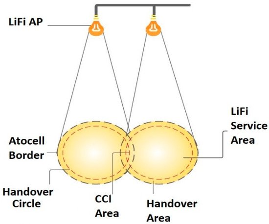
However, they participate in AP assignment and communication resource allocations. The LiFi AP covers a specific and limited area. Moreover, attocells are cells greater in scale than the communication in the LiFi network. A strong spatial spectrum quality can be obtained by reusing the bandwidth in each attocell [94]. The overlap zone, Optical Co-Channel Interference (CCI), is recognized and treated as noise because the same bandwidth is reused by all attocells [66]. The attocell diverges scale based on the source of illumination and the form of light. (iv) The distance between the AP and the region of irradiation. The attocell boundary represents the edge of the illuminated region. CCI occurs when two or more attocell users are linked as long as they remain inside the HO circle. This phenomenon is the same as that in the LiFi service area. Thus, users will connect to the AP and receive a LiFi signal from there. Other signal forms from another AP, such as Wi-Fi, may affect the area size [66]. As users across the HO zone borders, they would experience HO where they would remain inside the HO field. Depending on the algorithm used, such as the LB algorithm, this approach requires multiple milliseconds to seconds [66,79]. However, even within the HO zone, users will not experience HO in certain cases. This instance, which is termed as HO overhead [40,62,66,165,166], may occur even beyond the HO area because of other factors, such as: (i) the capacity of networks, (ii) the density for devices or users, (iii) signal intensity strength, and (iv) availability.
Using an IR light for UL can be a potential scheme for LiFi systems because IR light is invisible to the human eye. Using RF as a UL increases the complexity of combining space and time to increase the number of users who can access the network with a target value of rate per user. Managing transmissions by multiple users are necessary. To assure connectivity, UL coverage, and sufficient rate, multiple APs must be considered because the sole use of an AP may be inadequate. The opportunity of having the same signal copy at a different AP may induce interference if not adequately regulated through an access strategy. The ULR is called an IR detector, and it is typically placed in the ceiling at the AP beside the DLT, depending on the design that is being used. The CU controls both entities. In [95], the authors proposed a design for a UL with multiple users which consisted of five photodiodes. The UE refers to the user’s pieces of equipment, such as laptops, phones, or any other devices. A cell phone is supposed to face upwards for proper ULT because of the Vertical handover (VHO) and a complicated power allocation are required. The ULT greatly depends on the user and AP locations. For instance, when WiFi is used for UL, users can move more freely in the room without considering the device orientation. By contrast, UE should be placed upward to maintain a stable connection for systems that use IR for UL. An IR ULT smart Time Division Multiple Access (TDMA)-based scheme was proposed in [95]. The authors proposed a scheme with hybrid access that aimed to ULT and/or DLT are essential for a complete LiFi system. In Figure 7 , all the hardware components used in building, designing, or modelling a LiFi system network are proposed. To build, design, or study the architectural components of a LiFi system, understanding and investigating all the entities that must be included in the development of the LiFi systems are important. Figure 7 illustrates the essential components of infrastructure, AP side and UE side. The AP side includes Internet access [6], lamp driver, and light bulb, which represents the AP [137]; CU to control the flow of the data and support the LB and APA process [94]; and PLC or POE, which make to the use of the power lines as the medium of communication in the infrastructure among Internet servers [16,18,143,174], CU, and APs possible. The UE includes cell phone, PC, or a dongle, including a light detector, such as a PD or camera [118], solar cell [175], or PV [174,176], as receivers.
4. Comparison between LiFi and other OWC/RF Technologies
The OWC spectrum is unlicensed and offers better security [148] compared with RF-based wireless systems. However, many differences among them are noted, as shown in Table 4 . Table 5 shows a comparison of these technologies and explains the main differences between the LiFi system and the RF system in terms of elements, functionality, specifications, and other factors. Moreover, there are significant features and differences between LiFi and VLC; they both use existing illumination infrastructure [2,88,129]. The availability of VLC or LiFi attocells adds a new tier, creating three-tier networks [185]. LED luminaires or laser diodes (LDs) are used as transmitters, and photodetectors (PDs) are used as receivers in VLC. It can provide communication, lighting, and localization while using simply VL as a communication medium. VLC does not require mobility or illumination assistance. Sunlight and ambient light sources significantly impact VLC performance, rendering it inappropriate for outdoor applications.
LiFi, like VLC, employs LEDs or LDs as transmitters and PDs as receivers, as well as communication, illumination, and localisation. A LiFi system has a transmitter and a receiver at both ends of the transmission, allowing for bidirectional communication. Furthermore, it facilitates point-to-multipoint connections. Mobility and lighting support are required in LiFi. Sunlight and ambient light sources have a significant impact on LiFi functionality [185].
The studies [140,186], claims that LiFi and VLC both use a light-based technology for data transmission. VLC differs from LiFi because it is a unidirectional, point-to-point light communication system with lower data speeds. While LiFi is a networked, bidirectional, and high-speed wireless communication system. In contrast to VLC applications, infrared light is being examined for communication in LiFi and communication distances in LiFi limed to 10m while in VLC is 20m; moreover, VLC uses VL spectrum as a transmission medium while LiFi uses VL, UV and IR. Furthermore, LiFi uses PD as a receiver, while VLC uses PD and Camera. Moreover, LiFi and VLC have different standardization; LiFi standardisation is IEEE 802.11 bb, while VLC standardization is IEEE 802.15.7 [21,140].
LiFi and VLC both offer high data rates, but WiFi and small cells give relatively broader coverage for increased support for mobility. If LED transmitters are situated closely, VLC and LiFi systems suffer from interference effects [187]. In hybrid systems, similar to WiFi/VLC, WiFi/LiFi, and small cell/LiFi systems, macrocell/VLC and macrocell/LiFi hybrid systems also support offloading traffic to high-data, cheaper VLC and LiFi networks to enhance spectrum use, dependability of links, seamless movement, and security for optical wireless users. VLC and LiFi VLC are dislodging the increasingly large traffic in the macrocellular network. Traffic is routed across two networks in RF/VLC and RF/LiFi hybrid systems, ensuring improved service levels and maximising the use of resources. A hybrid system network can be selected based on the parameters such as traffic type, needed safety levels, required data rate, lighting requirements, mobility assistance and uplink/downlink service type [185].
This entry is adapted from the peer-reviewed paper 10.3390/app112311118