Your browser does not fully support modern features. Please upgrade for a smoother experience.
Please note this is an old version of this entry, which may differ significantly from the current revision.
Hollow box pultruded fibre-reinforced polymers (PFRP) profiles are increasingly used as structural elements in many structural applications due to their cost-effective manufacturing process, excellent mechanical properties-to-weight ratios, and superior corrosion resistance. Despite the extensive usage of PFRP profiles, there is still a lack of knowledge in the design for manufacturing against local buckling on the structural level.
- pultruded FRP profiles
- local buckling
- wall slenderness
- cross-sectional aspect ratio
- corner geometry
- layup properties
1. Introduction
Pultruded fibre-reinforced polymer (PFRP) profiles have flourished in the last few decades and have become a reliable construction element, especially after the research and development efforts that made pultrusion a more robust and economic manufacturing process [1,2]. These profiles developed from being strengthening and rehabilitating elements to being essential structural members because of their excellent mechanical properties, light weight, and superior corrosion resistance [3,4]. They are currently used as beams [5], decks and panels [6,7,8,9], and trusses [10,11,12] in buildings and bridges, frames in marine structures [13,14,15], lighting poles and cross-arms in infrastructure [16,17], pipes in the oil industry [18,19], spar caps for wind turbines and cable trays and grating walkways in solar structures in the energy sector [20,21], reinforcements for concrete [22,23], piles foundations [24,25], and sleepers in railways [26,27,28].
The introduction of pulwinding technology was one of the most prominent developments in pultrusion. In this process, off-axis wound fibres replace continuous filament mats to be pulled along with the axial fibre rovings, which enables the laminate to reach a higher value of fibre volume fraction with high-quality control and low defects (resin-rich zones) content. The wound fibres improve the transverse properties and delamination resistance and enhance the post-processing endurance, such as jointing and bolting [10,29].
2. Local Buckling in Composites
Pultruded FRP profiles are prone to local buckling failure, well below their ultimate load capacity, due to their anisotropic elasticity and application-driven slenderness [24,40]. Unlike other failure modes, which depend on the material strength, local buckling depends on the stiffness, geometry, and boundary and loading conditions of the element and can occur before reaching the strength limit [37,41,42]. Contrary to ductile and isotropic metals, the local buckling behaviour of FRP composites is different as it is usually accompanied by a growth of cracks and delamination [43,44].
The cross-sectional shape of the PFRP profiles controls their structural performance and their dominant failure mode [45,46,47]. Regarding local buckling behaviour, PFRP profiles are categorised into two groups of open-section and closed-section (box) shapes depending on the restraint provided for the flange, as shown in Figure 1. Figure 2 shows the percentage share of each cross-sectional shape in civil structural applications along with the studies characterising its local buckling behaviour. The circular tube shape was not considered here since local buckling is not critical in tubular PFRP profiles used in civil structural applications due to their relatively low slenderness ratio and uniformly distributed stresses [48,49,50,51]. The I-shape is most common in FRP profiles since it was inherited from the steel industry [52,53]. Nevertheless, box profiles are receiving more attention because of their higher structural stability and torsional stiffness with all walls being restrained [54]. Despite that, the majority of the local buckling studies were conducted on I-shape profiles, as shown in Figure 3, which compares the number of experimental studies undertaken on I-shape versus box shape in civil structural applications. The I-shape geometry was studied over three times more frequently than the box shape up to 2014. With the introduction of pulwinding technology for commercial production, the number of studies on box profiles was multiplied in 2014. Only three experimental studies on local buckling of pulwound FRP profiles were undertaken in 2014 [55], 2016 [56], and 2019 [29].
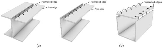
Figure 1. FRP composite profiles with (a) open-section and (b) closed-section (box) shapes (modified from [57]).
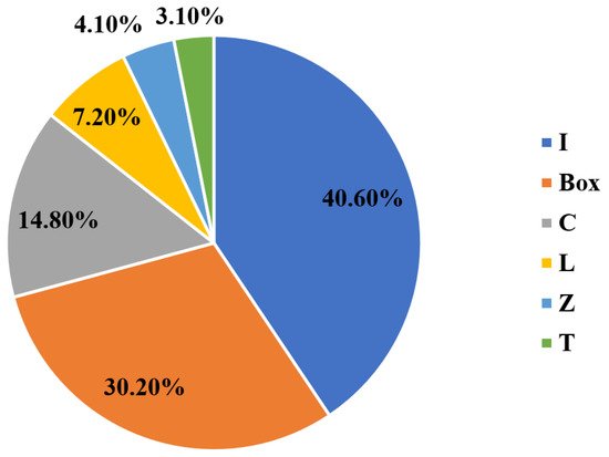
Figure 2. The percentage share of each cross-sectional shape in civil structural applications along with the studies (experimental and numerical) characterising its local buckling behaviour (I-shape: [17,52,53,57,58,59,60,61,62,63,64,65,66,67,68,69,70,71,72,73,74,75,76,77,78,79,80,81,82,83,84,85,86,87,88,89,90,91,92], Box-shape: [17,29,53,54,55,56,58,63,72,75,76,82,85,93,94,95,96,97,98,99,100,101,102,103,104,105,106,107,108], C-shape: [63,75,78,82,85,86,87,97,109,110,111,112,113,114,115], L-shape: [17,63,75,78,85,86,87], Z-shape: [78,85,86,87], and T-shape: [78,85,87]).
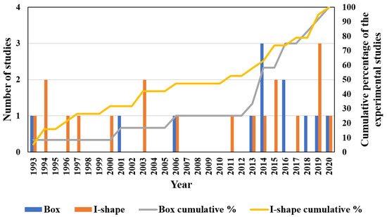
Figure 3. The number of experimental studies of local buckling undertaken on I-shape versus box shape for civil structural applications (Box-shape: [17,29,53,55,56,72,95,96,98,100,101,104] and I-shape: [17,53,61,62,64,66,67,68,69,70,71,72,77,79,81,89,90,91,92]).
3. Geometric Parameters of Hollow Box PFRP Profiles
The geometric parameters control the PFRP profile stability and determine its load capacity and failure mode [67,183].
3.1. Wall Slenderness
The wall slenderness (width-to-thickness ratio) significantly contributes to the local buckling capacity of thin-walled PFRP profiles [77,184]. Reducing the wall slenderness increases the profile stability and buckling capacity exponentially [152,167], and shifts the failure mode from local buckling to material compressive failure due to the increase in the flexural stiffness of the laminated walls [170,185]. The effect of the wall slenderness was studied extensively for laminated plate geometry subjected to uniaxial compressive load [133,143,146,152] and the effect of the layup properties on the buckling load capacity of slender plates was found to be negligible compared to their dimensions [137,144,153]. This finding agrees with the results of parametric studies on open-section PFRP columns [67,81,114], shown in Figure 8. When the slenderness ratio is reduced (thicker walls), the effect of the layup properties becomes significant. On the contrary, the effect of the layup properties becomes negligible when the wall slenderness is increased (thinner walls). Consequently, the layup properties should be considered carefully in the ultimate strength design of thick open-section profiles, while they can be considered only in the serviceability limit (deflection) design of thin open-section profiles [115]. However, the interaction of the wall slenderness with the other geometric parameters and failure modes of box profile geometry was not studied in the available literature.
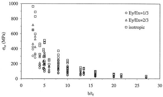
Figure 8. Critical buckling stresses versus the wall slenderness of I-shape PFRP profiles for different levels of orthotropy [81] (Ex and Ey are the longitudinal and transverse modulus, respectively).
3.2. Cross-Sectional Aspect Ratio
The cross-sectional aspect ratio (web height/flange width) defines the unsupported length of each wall and the major and minor axes of the cross-section. It affects the critical buckling load and stability of PFRP profiles [63] and alters their failure mode [186,187,188]. While maintaining a constant cross-sectional area, the flange and web buckling capacities were found to increase and decrease, respectively, when the cross-sectional aspect ratio is increased for both box [63] and open-section beams [172].
The significant effect of the cross-sectional aspect ratio was characterised under compression and bending for open-section profiles [59,86]. Increasing this ratio three times was found to decrease the buckling strength down to 42.8% under compression while it will increase the buckling strength up to 57.0% under bending. Moreover, the optimal cross-sectional aspect ratios of open-section PFRP profiles were investigated for column [65,109,111] and beam [65,82] applications. In addition, the interaction between the cross-sectional aspect ratio and the layup properties was studied for box [63] and I-shape [64] GFRP columns. The layup properties became insignificant when the flange width was increased and local buckling controlled it, as shown in Figure 11a,b, respectively.
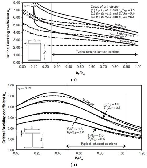
Figure 11. Buckling coefficient (k) versus bf/bw for different layup properties of (a) box [63] and (b) I-shape [64] GFRP columns.
3.3. Corner Geometry
The corner (flange-web junction) geometry of PFRP profiles is a critical manufacturing parameter affecting the production process, the pulling force, and the heated die settings. It is considered to be a weak point of premature failure due to stresses concentration at this critical zone [189,190,191]. It is recommended to increase the inner corner radius (fillet) to prevent cracking by uniformly distributing the stresses and preventing their concentration [192], as shown in Figure 15. Increasing the outer corner radius to be equal to the inner radius plus the wall thickness can also facilitate the production process and help to avoid thermal-induced cracks [192].
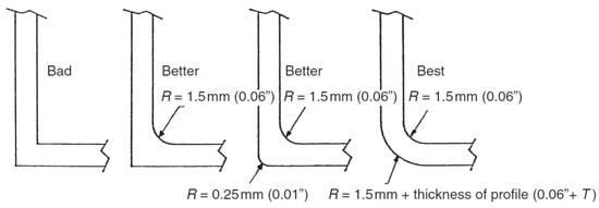
Figure 15. Recommended configurations of the corner of PFRP profiles [192].
4. Layup Parameters of Hollow Box PFRP Profiles
The layup properties define the anisotropy and mechanical properties of FRP profiles in the longitudinal and transverse directions and directly affect their local buckling behaviour [193]. These properties should be designed depending on the intended application since the design will address a specific geometry and loading condition and cannot be generalised for all composite structures [143,194].
4.1. Axial-to-Inclined Fibre Ratio
For civil structural applications, the layup of PFRP profiles consists of longitudinal fibre rovings to obtain the required axial and flexural stiffness and off-axis (inclined) fibres to enhance the shear and transverse properties [42,195]. The ratio of these axial-to-inclined fibres shapes the anisotropy and mechanical properties of the laminated walls to achieve the required axial and flexural stiffness and the desired shear and transverse properties. In general, it is recommended to add inclined fibres along with the axial plies to enhance the off-axis mechanical properties, damage tolerance, and stability of laminated plates [196,197]. These inclined fibres are also needed to fulfil the web stiffness and strength requirements of PFRP beams [198,199].
Regarding the geometry effect on this ratio, it was found that increasing the axial fibre percentage will increase axial buckling resistance of laminated plates [123]. On the contrary, increasing the inclined fibre percentage will increase the local buckling strength of open-section FRP columns due to the higher rotational rigidity between the orthogonal walls [200]. No study was found on the interaction between the axial-to-inclined fibre ratio and the other layup properties or on its effect on the geometric parameters of pulwound box FRP profiles.
4.2. Inclined Fibre Angle
The optimal fibre angle to obtain the maximum buckling capacity is a function of the geometry, boundary condition, and loading condition [133,143,194]. Under flexural loading, it was found that increasing the web orthotropy exhibits the highest increase in the buckling capacity of the flange due to the increase in the rotational restraint at the flange-web junction. Moreover, the increase in the flange buckling capacity is higher when its orthotropy is low [54]. For open-section FRP beams, the buckling load was found to decrease when the fibre angle is increased [58].
Moreover, the interaction between the fibre angle and the stacking sequence was found to be significant and may shift the optimal fibre angle depending on the geometry and boundary and loading conditions [149,168]. For instance, antisymmetric laminated plates require a fibre angle of to obtain the maximum buckling load unlike symmetric laminates [157]. Even for symmetric layups, the optimal fibre angle for maximum buckling of GFRP cylindrical shells changes depending on the introduction or removal of axial fibres [167], as shown in Figure 18. Stacking the inclined plies at the outer side to confine the axial fibres enhances the buckling capacity. Regarding the pulwound FRP profiles, no study was found to investigate the winding angle effect on the corner geometry or its interactions with the other layup parameters under compression or bending. Assessing the contribution of this parameter on the buckling resistance of pulwound box PFRP profiles will alleviate the lack of knowledge for this special shape.
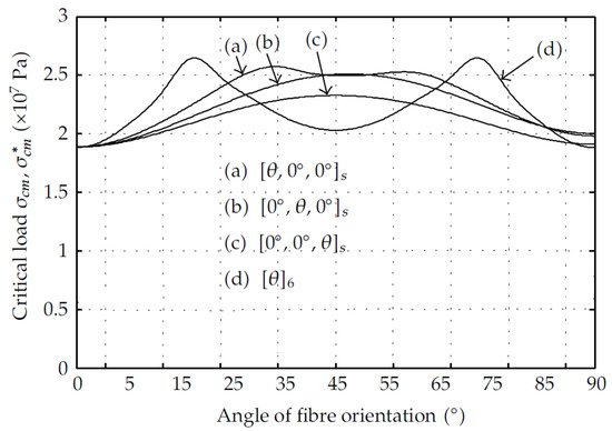
Figure 18. Critical buckling load versus varying inclined fibre orientation for different stacking sequences in GFRP cylindrical shells [167].
This entry is adapted from the peer-reviewed paper 10.3390/polym13234159
This entry is offline, you can click here to edit this entry!