Since its inception more than thirty years ago, electroformation has become the most commonly used method for growing giant unilamellar vesicles (GUVs). Although the method seems quite straightforward at first, researchers must consider the interplay of a large number of parameters, different lipid compositions, and internal solutions in order to avoid artifactual results or reproducibility problems.
- electroformation
- GUVs
- cholesterol
- lipid composition
1. Introduction
Artificial vesicles have become an important research tool due to their similarity to biological membranes [1][2][3][4][5][6]. Being lab-created, they enable the study of membrane properties under controlled conditions. When mimicking the biological membrane, we are interested mainly in unilamellar vesicles (only one outer bilayer), but multilamellar (bilayers arranged in concentric circles) and oligolamellar vesicles (containing smaller ones inside) can also be created. Depending on their size, unilamellar vesicles are commonly divided into three groups: small (SUVs, <100 nm), large (LUVs, 100 nm–1 μ m), and giant unilamellar vesicles (GUVs, >1 μ m). SUVs and LUVs are more often studied in the context of drug delivery applications [7][8][9]. GUVs are more useful as artificial cell models for eukaryotic cells due to similarity in size. Additionally, their size enables observation of membrane domain structure using light microscopy.
2. Classic Electroformation Protocol
One of the earliest attempts at forming GUVs was the natural swelling method introduced by Reeves and Dowben in 1969 [3]. According to this method, a lipid solution is deposited on a surface and dried to form a lipid film. The lipid film is then rehydrated and the obtained solution gently stirred to form vesicles. The vesicles are formed mainly due to the osmotic pressure driving the aqueous solution in between the stacked lipid bilayers. Exposing the hydrophobic portion of the bilayer to aqueous solutions is unfavourable and causes them to close up into vesicles. However, the proportion of GUVs that can be generated using this method is small, as most of them are either multilamellar or display other types of defects [10]. In their efforts to devise a protocol that reliably produces a high proportion of cell-sized unilamellar vesicles, Angelova and Dimitrov applied an external electric field during lipid swelling and thus invented the electroformation method [11]. Although the exact mechanism of the method is not yet completely understood, it is believed that the electric field affects lipid swelling through direct electrostatic interactions, redistribution of counterions, changes in membrane surface and line tension, and electroosmotic flow effects [12]. More detailed theoretical discussions on the electroformation mechanism can be found elsewhere [13][14][15].
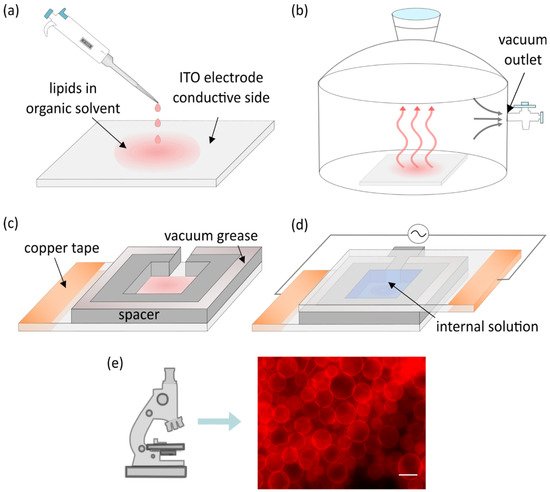
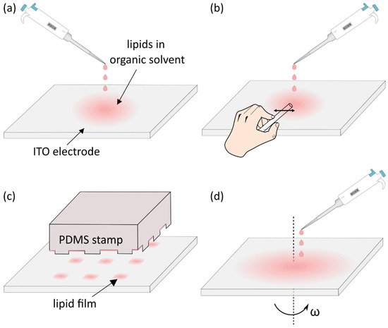
Although Angelova and Dimitrov used platinum wires for electroformation, indium tin oxide (ITO) electrodes are most commonly used nowadays, so we utilize them in our description of the basic protocol. The only difference between these two protocols is the electroformation chamber layout. The protocol starts with droplets of lipids dissolved in an organic solvent being deposited onto the electrode ( Figure 1a). In addition to lipids, fluorescent dyes are present in the mixture in small quantities to enable the usage of fluorescent microscopy later on.
The solvent is evaporated under vacuum or a stream of inert gas ( Figure 1b). A spacer is attached to the electrode using vacuum grease ( Figure 1c). Another electrode is then attached to the spacer with its conductive side facing inward. Following that, the chamber is filled with an internal solution of choice and connected to a voltage source while maintaining a temperature higher than the phase transition temperature of deposited lipids. Copper tape is often attached to the electrodes to provide better contact with the alternating current function generator ( Figure 1d). The combination of the electric field and lipid film hydration leads to the creation of lipid vesicles which can be observed under a microscope ( Figure 1e).
At first, direct current was used, but water electrolysis led to formation of bubbles [11], so a transition to alternating currents was made [11][12]. Alternating currents also introduce electroosmotic motion of the fluid, which facilitates the destabilization of the lipid film, thus promoting the formation of vesicles [12][16]. Over the years, the initial protocol has been modified in order to increase the yield, homogeneity, and compositional uniformity of the vesicles or to enable preparation of GUVs from previously incompatible lipids and buffers.
3. Electrode Materials and Cleaning
4. Deposition of the Lipid Solution and Removal of the Solvent
5. Temperature and Electroformation Duration
6. Vesicles Population Count and Size
Light scattering methods are a popular tool for determining the average diameter of particles suspended in a solution. For particles up to a diameter of around 1 μ m, methods such as dynamic light scattering can be used to easily obtain the average diameter value [53]. Since GUVs fall out of this size category, the most commonly used light scattering method is flow cytometry [18][52][54][55][56][57][58]. Studies have been performed to confirm the correlation between the forward scatter (FSC) and side scatter (SSC) signal intensity and particle size. For example, the correlation for smaller particles ( ~ 1 µm) has been confirmed using dynamic light scattering measurements [53] and for larger ones ( ~ 10 µm) by observing liposomes under a microscope after fluorescence-activated cell sorting [55]. Consequently, to obtain the average liposome diameter, sample FSC and/or SSC signals are measured and compared with those of calibration beads (usually polystyrene or silica) of known size.
The problem with this approach is that the FSC and SSC signals depend on the internal structure of the particles as well as their refractive indices, giving rise to a certain amount of error in obtained diameters [53][59]. Usually, researchers are content with obtained relative sizing but comment on the possibility of error due to the refractive index mismatch. Possible solutions have been offered to account for the difference. One study first obtained the average refractive index of particles of interest and then corrected the calibration beads measurements using the Mie scattering theory [59]. Another study took a more direct approach and proposed artificial liposomes as calibrators instead of polystyrene beads [54]. An additional detail which is easily missed is that all of the articles above use FSC and/or SSC to extract the dimensions of the particles. However, when particles are approximately the same size as the height of the laser beam (as is the case for most GUVs), pulse width sizing is probably a better approach for determining the size of vesicles as it does not depend on many of the factors plaguing light scattering approaches for size measurements [60][61].
Recently, imaging flow cytometry devices started being used for GUV quantification [57]. This unites the best of both worlds by combining the rapid analysis of thousands of particles using flow cytometry with the capability of image-based approaches to identify the results.
Coulter counters detect particles suspended in an electrolyte based on the change of impedance due to the passing of a particle through an aperture between the two electrodes [62]. In terms of potential for analysis of GUVs, the method has an advantage of being able to detect the size of particles as well as their number.
This entry is adapted from the peer-reviewed paper 10.3390/membranes11110860
References
- Menger, F.M.; Angelova, M.I. Giant vesicles: Imitating the cytological processes of cell membranes. Acc. Chem. Res. 1998, 31, 789–797.
- Veatch, S.L.; Keller, S.L. Organization in lipid membranes containing cholesterol. Phys. Rev. Lett. 2002, 89, 268101.
- Reeves, J.P.; Dowben, R.M. Formation and properties of thin-walled phospholipid vesicles. J. Cell. Physiol. 1969, 73, 49–60.
- Pott, T.; Bouvrais, H.; Méléard, P. Giant unilamellar vesicle formation under physiologically relevant conditions. Chem. Phys. Lipids 2008, 154, 115–119.
- Valkenier, H.; López Mora, N.; Kros, A.; Davis, A.P. Visualization and quantification of transmembrane ion transport into giant unilamellar vesicles. Angew. Chemie Int. Ed. 2015, 54, 2137–2141.
- Subczynski, W.; Raguz, M.; Widomska, J. Studying lipid organization in biological membranes using liposomes and EPR spin labeling. Methods Mol. Biol. 2010, 606, 247–269.
- Zylberberg, C.; Matosevic, S. Pharmaceutical liposomal drug delivery: A review of new delivery systems and a look at the regulatory landscape. Drug Deliv. 2016, 23, 3319–3329.
- Sercombe, L.; Veerati, T.; Moheimani, F.; Wu, S.Y.; Sood, A.K.; Hua, S. Advances and Challenges of Liposome Assisted Drug Delivery. Front. Pharmacol. 2015, 6, 286.
- Akbarzadeh, A.; Rezaei-Sadabady, R.; Davaran, S.; Joo, S.W.; Zarghami, N.; Hanifehpour, Y.; Samiei, M.; Kouhi, M.; Nejati-Koshki, K. Liposome: Classification, preparation, and applications. Nanoscale Res. Lett. 2013, 8, 102.
- Rodriguez, N.; Pincet, F.; Cribier, S. Giant vesicles formed by gentle hydration and electroformation: A comparison by fluorescence microscopy. Colloids Surf. B Biointerfaces 2005, 42, 125–130.
- Angelova, M.I.; Dimitrov, D.S. Liposome electroformation. Faraday Discuss. Chem. Soc. 1986, 81, 303–311.
- Dimitrov, D.S.; Angelova, M.I. Lipid swelling and liposome formation on solid surfaces in external electric fields. In New Trends in Colloid Science; Springer: Berlin/Heidelberg, Germany, 1987; pp. 48–56.
- Has, C.; Pan, S. Vesicle formation mechanisms: An overview. J. Liposome Res. 2020, 31, 90–111.
- Li, W.; Wang, Q.; Yang, Z.; Wang, W.; Cao, Y.; Hu, N.; Luo, H.; Liao, Y.; Yang, J. Impacts of electrical parameters on the electroformation of giant vesicles on ITO glass chips. Colloids Surf. B Biointerfaces 2016, 140, 560–566.
- Li, Q.; Wang, X.; Ma, S.; Zhang, Y.; Han, X. Electroformation of giant unilamellar vesicles in saline solution. Colloids Surf. B Biointerfaces 2016, 147, 368–375.
- Angelova, M.; Dimitrov, D.S. A mechanism of liposome electroformation. In Trends in Colloid and Interface Science II; Springer: Berlin/Heidelberg, Germany, 1988; pp. 59–67.
- Herold, C.; Chwastek, G.; Schwille, P.; Petrov, E.P. Efficient electroformation of supergiant unilamellar vesicles containing cationic lipids on ITO-coated electrodes. Langmuir 2012, 28, 5518–5521.
- Drabik, D.; Doskocz, J.; Przybyło, M. Effects of electroformation protocol parameters on quality of homogeneous GUV populations. Chem. Phys. Lipids 2018, 212, 88–95.
- Pereno, V.; Carugo, D.; Bau, L.; Sezgin, E.; Bernardino De La Serna, J.; Eggeling, C.; Stride, E. Electroformation of Giant Unilamellar Vesicles on Stainless Steel Electrodes. ACS Omega 2017, 2, 994–1002.
- Behuria, H.G.; Biswal, B.K.; Sahu, S.K. Electroformation of liposomes and phytosomes using copper electrode. J. Liposome Res. 2021, 31, 255–266.
- Morales-Penningston, N.F.; Wu, J.; Farkas, E.R.; Goh, S.L.; Konyakhina, T.M.; Zheng, J.Y.; Webb, W.W.; Feigenson, G.W. GUV preparation and imaging: Minimizing artifacts. Biochim. Biophys. Acta-Biomembr. 2010, 1798, 1324–1332.
- Ayuyan, A.G.; Cohen, F.S. Lipid peroxides promote large rafts: Effects of excitation of probes in fluorescence microscopy and electrochemical reactions during vesicle formation. Biophys. J. 2006, 91, 2172–2183.
- Zhou, Y.; Berry, C.K.; Storer, P.A.; Raphael, R.M. Peroxidation of polyunsaturated phosphatidyl-choline lipids during electroformation. Biomaterials 2007, 28, 1298–1306.
- Farkas, E.R.; Webb, W.W. Multiphoton polarization imaging of steady-state molecular order in ternary lipid vesicles for the purpose of lipid phase assignment. J. Phys. Chem. B 2010, 114, 15512–15522.
- Okumura, Y.; Sugiyama, T. Electroformation of Giant Vesicles on a Polymer Mesh. Membranes 2011, 1, 184–194.
- Okumura, Y.; Zhang, H.; Sugiyama, T.; Iwata, Y. Electroformation of giant vesicles on a non-electroconductive substrate. J. Am. Chem. Soc. 2007, 129, 1490–1491.
- Lefrançois, P.; Goudeau, B.; Arbault, S. Electroformation of phospholipid giant unilamellar vesicles in physiological phosphate buffer. Integr. Biol. 2018, 10, 429–434.
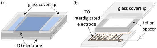
- Bi, H.; Yang, B.; Wang, L.; Cao, W.; Han, X. Electroformation of giant unilamellar vesicles using interdigitated ITO electrodes. J. Mater. Chem. A 2013, 1, 7125–7130.
- Baykal-Caglar, E.; Hassan-Zadeh, E.; Saremi, B.; Huang, J. Preparation of giant unilamellar vesicles from damp lipid film for better lipid compositional uniformity. Biochim. Biophys. Acta-Biomembr. 2012, 1818, 2598–2604.
- Zhao, J.; Wu, J.; Shao, H.; Kong, F.; Jain, N.; Hunt, G.; Feigenson, G. Phase studies of model biomembranes: Macroscopic coexistence of Lα + Lβ, with light-induced coexistence of Lα + Lo Phases. Biochim. Biophys. Acta-Biomembr. 2007, 1768, 2777–2786.
- Witkowska, A.; Jablonski, L.; Jahn, R. A convenient protocol for generating giant unilamellar vesicles containing SNARE proteins using electroformation. Sci. Rep. 2018, 8, 9422.
- Estes, D.J.; Mayer, M. Electroformation of giant liposomes from spin-coated films of lipids. Colloids Surf. B Biointerfaces 2005, 42, 115–123.
- Politano, T.J.; Froude, V.E.; Jing, B.; Zhu, Y. AC-electric field dependent electroformation of giant lipid vesicles. Colloids Surf. B Biointerfaces 2010, 79, 75–82.
- Veatch, S.L. Electro-formation and fluorescence microscopy of giant vesicles with coexisting liquid phases. Methods Mol. Biol. 2007, 398, 59–72.
- Stein, H.; Spindler, S.; Bonakdar, N.; Wang, C. Production of Isolated Giant Unilamellar Vesicles under High Salt Concentrations. Front. Physiol. 2017, 8, 1–16.
- Boban, Z.; Puljas, A.; Kovač, D.; Subczynski, W.K.; Raguz, M. Effect of Electrical Parameters and Cholesterol Concentration on Giant Unilamellar Vesicles Electroformation. Cell Biochem. Biophys. 2020, 78, 157–164.
- Angelova, M.I.; Soléau, S.; Méléard, P.; Faucon, F.; Bothorel, P. Preparation of giant vesicles by external AC electric fields. Kinetics and applications. In Trends in Colloid and Interface Science VI; Springer: Berlin/Heidelberg, Germany, 1992; pp. 127–131.
- Ghellab, S.E.; Mu, W.; Li, Q.; Han, X. Prediction of the size of electroformed giant unilamellar vesicle using response surface methodology. Biophys. Chem. 2019, 253, 106217.
- Gracià, R.S.; Bezlyepkina, N.; Knorr, R.L.; Lipowsky, R.; Dimova, R. Effect of cholesterol on the rigidity of saturated and unsaturated membranes: Fluctuation and electrodeformation analysis of giant vesicles. Soft Matter 2010, 6, 1472–1482.
- Taylor, P.; Xu, C.; Fletcher, P.D.I.; Paunov, V.N. A novel technique for preparation of monodisperse giant liposomes. Chem. Commun. 2003, 44, 1732–1733.
- Berre, L.; Chen, Y.; Baigl, D. From Convective Assembly to Landau—Levich Deposition of Multilayered Phospholipid Films of Controlled Thickness. Langmuir 2009, 2554–2557.
- Huang, J.; Buboltz, J.T.; Feigenson, G.W. Maximum solubility of cholesterol in phosphatidylcholine and phosphatidylethanolamine bilayers. Biochim. Biophys. Acta-Biomembr. 1999, 1417, 89–100.
- Bagatolli, L.A.; Parasassi, T.; Gratton, E. Giant phospholipid vesicles: Comparison among the whole lipid sample characteristics using different preparation methods: A two photon fluorescence microscopy study. Chem. Phys. Lipids 2000, 105, 135–147.
- Collins, M.D.; Gordon, S.E. Giant liposome preparation for imaging and patch-clamp electrophysiology. J. Vis. Exp. 2013, 76, e50227.
- Oropeza-Guzman, E.; Riós-Ramírez, M.; Ruiz-Suárez, J.C. Leveraging the Coffee Ring Effect for a Defect-Free Electroformation of Giant Unilamellar Vesicles. Langmuir 2019, 35, 16528–16535.
- Bhatia, T.; Husen, P.; Brewer, J.; Bagatolli, L.A.; Hansen, P.L.; Ipsen, J.H.; Mouritsen, O.G. Preparing giant unilamellar vesicles (GUVs) of complex lipid mixtures on demand: Mixing small unilamellar vesicles of compositionally heterogeneous mixtures. Biochim. Biophys. Acta-Biomembr. 2015, 1848, 3175–3180.
- Girard, P.; Pécréaux, J.; Lenoir, G.; Falson, P.; Rigaud, J.L.; Bassereau, P. A new method for the reconstitution of membrane proteins into giant unilamellar vesicles. Biophys. J. 2004, 87, 419–429.
- Shimanouchi, T.; Umakoshi, H.; Kuboi, R. Kinetic Study on Giant Vesicle Formation with Electroformation Method. Langmuir 2009, 25, 4835–4840.
- Betaneli, V.; Worch, R.; Schwille, P. Effect of temperature on the formation of liquid phase-separating giant unilamellar vesicles (GUV). Chem. Phys. Lipids 2012, 165, 630–637.
- Jørgensen, K.; Mouritsen, O.G. Phase separation dynamics and lateral organization of two-component lipid membranes. Biophys. J. 1995, 69, 942–954.
- De Almeida, R.F.M.; Loura, L.M.S.; Fedorov, A.; Prieto, M. Nonequilibrium Phenomena in the Phase Separation of a Two-Component Lipid Bilayer. Biophys. J. 2002, 82, 823–834.
- Breton, M.; Amirkavei, M.; Mir, L.M. Optimization of the Electroformation of Giant Unilamellar Vesicles (GUVs) with Unsaturated Phospholipids. J. Membr. Biol. 2015, 248, 827–835.
- Vorauer-Uhl, K.; Wagner, A.; Borth, N.; Katinger, H. Determination of liposome size distribution by flow cytometry. Cytometry 2000, 39, 166–171.
- Simonsen, J.B. A liposome-based size calibration method for measuring microvesicles by flow cytometry. J. Thromb. Haemost. 2016, 14, 186–190.
- Sato, K.; Obinata, K.; Sugawara, T.; Urabe, I.; Yomo, T. Quantification of structural properties of cell-sized individual liposomes by flow cytometry. J. Biosci. Bioeng. 2006, 3, 171–178.
- Hema Sagar, G.; Tiwari, M.D.; Bellare, J.R. Flow cytometry as a novel tool to evaluate and separate vesicles using characteristic scatter signatures. J. Phys. Chem. B 2010, 114, 10010–10016.
- Matsushita-Ishiodori, Y.; Hanczyc, M.M.; Wang, A.; Szostak, J.W.; Yomo, T. Using imaging flow cytometry to quantify and optimize giant vesicle production by water-in-oil emulsion transfer methods. Langmuir 2019, 35, 2375–2382.
- Nishimura, K.; Hosoi, T.; Sunami, T.; Toyota, T.; Fujinami, M.; Oguma, K.; Matsuura, T.; Suzuki, H.; Yomo, T. Population analysis of structural properties of giant liposomes by flow cytometry. Langmuir 2009, 25, 10439–10443.
- van der Pol, E.; Coumans, F.A.W.; Grootemaat, A.E.; Gardiner, C.; Sargent, I.L.; Harrison, P.; Sturk, A.; van Leeuwen, T.G.; Nieuwland, R. Particle size distribution of exosomes and microvesicles determined by transmission electron microscopy, flow cytometry, nanoparticle tracking analysis, and resistive pulse sensing. J. Thromb. Haemost. 2014, 12, 1182–1192.
- Hoffman, R.A. Pulse width for particle sizing. Curr. Protoc. Cytom. 2009, 1, 1–17.
- Kang, K.; Lee, S.B.; Yoo, J.H.; Nho, C.W. Flow cytometric fluorescence pulse width analysis of etoposide-induced nuclear enlargement in HCT116 cells. Biotechnol. Lett. 2010, 32, 1045–1052.
- Vembadi, A.; Menachery, A.; Qasaimeh, M.A. Cell Cytometry: Review and Perspective on Biotechnological Advances. Front. Bioeng. Biotechnol. 2019, 7, 147.