With the rapid growth of space optics and aerospace technology, the applications of reflective optical systems are increasing year by year. A case in point is that off-axis three-mirror-anastigmat (TMA) systems have been widely used due to their unique advantages of large aperture and no central occlusion. Meanwhile, the growing requirements for optical systems’ performance, such as resolution and imaging quality, drive the development of focal length and aperture to larger sizes. In turn, the weight, surface accuracy, manufacturing time, and mirror cost are progressively demanding. In recent years, the lightweight space camera used for remote sensing with high resolution has become a global research hotspot in advanced optics.
1. Additive Manufacturing Technology for Metal Mirrors
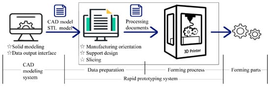
Additive manufacturing (AM), more commonly known as three-dimensional (3D) printing, is a rapid prototyping technology. It is a craft of manufacturing parts layer-upon-layer based on a digital model file. The specific process creates 3D models using computer-aided design (CAD) software and then slices and designs support through 3D-printing software. Finally, all the information is sent to a 3D printer, which stacks two-dimensional (2D) slices until the product is manufactured (
Figure 5) [
25].
Figure 5. Process flow chart of AM.
AM is a manufacturing method of “bottom-up” accumulation compared with the conventional machining mode. This makes it possible to manufacture novel geometries, complex structures, and customized parts limited by conventional processing methods [
26]. AM offers some advantages, such as material savings, design freedom, parts almost in their final shape, design freedom, and reduction of time to market. It has been used wildly in aerospace, biomedicine, and automotive parts manufacturing.
2. Metal Additive Manufacturing Technology
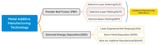
Metal AM technologies fall into two categories: (
Figure 6) powder-bed fusion (PBF) and directed energy deposition (DED). DED covers 16% of the metal AM market and uses laser beams, electron beams, or electric arcs as energy sources to deposit the melting powder. It uses coaxial or lateral powder feeding methods, which are more practical than PBF’s laying powder. Still, the accuracy of DEDed products is not as high as the PBFed. DED is more suitable for manufacturing large and high-performance integral components. PBF is ideal for small, ultra-complex monolithic components such as metal mirrors, owing to its products’ good surface finish and high density [
27,
28].
Figure 6. Classification of metal AM technology.
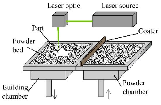
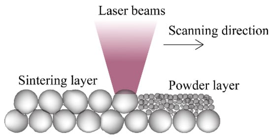
Figure 7 shows the schematic of SLS. The first step is to coat a layer of powder on the platform, then preheat the powder to near the melting point to reduce the residual stress. After that, the laser beams illuminate specific areas on the cross-section according to the data of the corresponding sliced model’s layer. Using the same technique, repeat the process of laying powder and sintering until a part forms. The principles of other PBF techniques are similar to this, repeating the coating and scanning processes. Table 3 presents an overview of the materials and AM technologies for fabricating metal mirrors in recent years. It can be seen that all the mirrors are fabricated using PBF, namely EBM, SLS/DMLS, and SLM. The most common choice is printing AlSi10Mg via SLM. This section describes several PBF technologies and compares the pros and cons of each process for AM.
Figure 7. Schematic diagram of SLS.
Table 3. Summary of materials and AM technologies of manufacturing metal mirrors in recent years.
| R and D Unit |
Time |
Material |
Technology Type |
Surface Accuracy |
| Corning [29] |
2015 |
AlSi7Mg0.3 |
DMLS |
1.5 nm (RMS) |
| General Dynamics [21] |
2015 |
AlSi10Mg |
DMLS |
43.2 nm (RMS) |
| University of Arizona [30] |
2015 |
AlSi10Mg |
DMLS |
255 nm (PV) |
| University of Arizona [30] |
2015 |
Ti6Al4V |
EBM |
/ |
| Lockheed Martin [31] |
2016 |
AlSi10Mg |
SLM |
/ |
| Optimax Systems [32] |
2017 |
FeNi36 |
SLM |
/ |
| IOF [33] |
2018 |
AlSi12 |
SLM |
12.5 nm (RMS) |
| IOF [34] |
2019 |
AlSi40 |
SLM |
7.3 nm (RMS) |
| UKAT [18,35,36] |
2020 |
AlSi10Mg |
DMLS |
16 nm |
| CIOMP [37] |
2020 |
AlSi10Mg |
SLM |
58 nm (RMS) |
2.1. Electron Beam Melting (EBM)
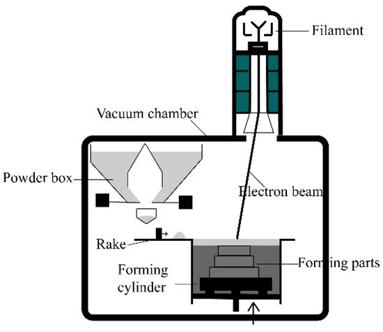
EBM was invented in 1993 in Sweden at the University of Technology in Gothenburg. Arcam was founded in 1997 and sold its first commercial system in 2002. The most significant difference between EBM and the other two PBF technologies is that the heat source replaces laser beams with electron beams. The EBM system consists of an electron beam gun, vacuum chamber, forming a cylinder, and powder distribution mechanisms (
Figure 8). In a vacuum environment, high-energy fast electron beams are controlled to melt the powder selectively and build up a forming part [
38].
Figure 8. Schematic diagram of EBM system.
The power of electron beams is about 3–6 kW, which is an order of magnitude higher than laser beams. At the same time, the EBM has the advantage of high energy utilization. EBM is suitable for printing high melting temperature powders such as Ti alloy. Moreover, EBM is not influenced by the optical reflectivity of the powder. However, the disadvantages of EBM are also evident. Intense X-rays can be produced during EBM, and therefore adequate protection measures must be taken. Besides, EBM has limited dimensions for building parts, with a maximum diameter of 350 mm and a height of 380 mm. Due to the unique energy conversion mechanism of the electron beam, serious liquid metal splash which results in porosity occurs in the process of printing aluminum alloy via EBM. Furthermore, the precision of printing is low. There are few reports on fabricating Al alloys by EBM to date because of its process characteristics [
39]. In the research on metal mirrors, only the University of Arizona used EBM to print a Ti alloy mirror. Its surface was poor, so EBM is not an appropriate technology for mirrors.
2.2. Selective Laser Sintering (SLS)
SLS was developed by C.R. Dechard at the University of Texas in 1989. Sintering uses a laser beam as the heat source to melt part of the powder with a low melting point so that transient wetting liquid promotes metallurgical bonding or inter-particulate melting across the layers of sintered components (
Figure 9). The powder with high melting point bonds together after the liquid metal solidifies and then forms a rough component, achieving the liquid-phase sintering effect [
40]. Due to only partial melting, the surface quality and density of the forming parts are poor. Hence, SLS cannot meet the requirements for high-precision metal mirrors.
Figure 9. Schematic diagram of laser sintering.The powder composition of SLS is a mixture of high and low melting point powder, mainly nylon, polyamide, and other polymers. For metal SLS, it can be further divided into indirect metal laser sintering and direct metal laser sintering (DMLS) according to powder composition. The binder material for DMLS is a metal powder with a low melting point, while polymer powder is for indirect metal sintering. Researchers began utilizing DMLS to fabricate aluminum mirrors around 2015 when AM metal mirrors were still in the initial exploration stage. However, DMLS has been gradually replaced by SLM in the field of mirror manufacturing due to the progress of AM technologies.
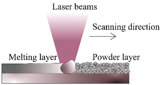
2.3. Selective Laser Melting (SLM)
SLM based on SLS was proposed by the Institute of Fraunhofer in Germany in 1995 and successfully developed in 2002. It integrates the advantages of SLS, which melts powders layer-by-layer and forms under the protection of inert gas to prevent the reaction between powder and other gas. The main difference between the two is that SLM can achieve full melting, as shown in
Figure 10, in a single component, single material powder, and was initially applied only to pure metals [
41]. In contrast, SLS processes cannot heat the powders above the melting temperature and form parts with somewhat less than ideal density. Meanwhile, its equipment price and process complexity are above SLS.
Figure 10. Schematic diagram of laser melting.
SLM is a technology that has been commonly used to manufacture metal mirrors in recent years, as shown in
Table 3. In theory, forming parts via SLM have higher density and mechanical properties than via laser sintering. SLM’s products have high dimensional accuracy, a smooth surface, and high density [
42]. The laser power of SLM solutions’ 3D printer can reach 700 W easily, which is high enough to pre-print mirror blanks. SLMed parts’ density is up to 99.0% and above. The above technical advantages have gradually promoted SLM to the mainstream technology for fabricating AM metal mirrors.
3. Additive Manufacturing Metal Mirror Fabricating Considerations
3.1. Material Type
With the continuous development of AM technologies, printing materials have become increasingly abundant. At present, there are more than 300 kinds of materials for AM, mainly polymers, metals, ceramics, and biomaterials [
43]. Metal materials that are frequently used are aluminum alloys, titanium alloys, nickel-based superalloys, stainless steel, and iron alloys. However, the representative materials are still Al alloy and Ti alloy for metal mirrors, which dominate 3D-printed metal mirrors. In 2015, Herzog fabricated AlSi
10Mg and Ti6Al4V mirror blanks using SLM and EBM [
30], respectively. Nevertheless, after optical post-processing, the mirror surface of the final Ti mirror was far from the requirements. The details of this are further described in
Section 3. Therefore, aluminum alloy is the material which more widely used to fabricate AM metal mirrors.
At present, the aluminum alloys used in manufacturing mirrors are mainly Al-Si alloy and Al-Mg-Si alloy, including AlSi
7Mg
0.6, AlSi
10Mg, AlSi
12, and AlSi
40. The addition of silicon improves the fluidity of aluminum and reduces its melting temperature. Adding magnesium to aluminum can not only improve its strength but also improve its strain-hardening ability. AlSi
10Mg is the Al alloy which most intensively investigated, and the technology of printing AlSi
10Mg by PBF is very mature.
Table 4 provides the multiple parameters of PBFed AlSi
10Mg and as-cast AlSi
10Mg after the high pressure of die-cast (HPDC). The ultimate tensile strength and ductility values in additively manufactured AlSi
10Mg are generally higher than or equal to as-cast and HPDC AlSi
10Mg, which can be attributed to the fine microstructures seen in AM samples [
28]. Therefore, the AlSi
10Mg mirrors have excellent microstructure and mechanical properties. However, in engineering, the designers should consider the system requirements, prefabricating techniques, and post-treatment to make the best material choice.
Table 4. Processing parameters and mechanical properties of AlSi10Mg alloys fabricated by AM compared to their traditionally processed counterparts [
28]. (P = Laser power,
υ = Scanning speed, H = Linear heat input, q = Density, E = Elastic modulus,
σy = Yield strength,
σuts = Ultimate tensile strength, HV = Vickers hardness).
| Manufacturing Method |
P (W) |
υ (mm/s) |
H (J/mm) |
Post-Treatment |
Orientation |
E (GPa) |
σy (MPa) |
σuts (MPa) |
Ductility (%) |
HV |
| PBF |
250 |
500 |
0.50 |
As built |
Longitudinal
Transverse |
|
250
240 |
350
280 |
2.5
1.2 |
145 |
| |
|
|
|
T6 |
Longitudinal
Transverse |
|
285
290 |
340
330 |
4.5
2.2 |
116 |
| |
250 |
500 |
0.5 |
As built |
Longitudinal
Transverse |
|
125
140 |
250
270 |
6.6
4.6 |
75 |
| |
|
|
|
T6 |
Longitudinal
Transverse |
|
295
285 |
350
340 |
6.5
4.9 |
118 |
| |
|
|
|
As built |
Longitudinal
Transverse |
75 ± 10
70 ± 10 |
270 ± 10
240 ± 10 |
460 ± 20
460 ± 20 |
9 ± 2
6 ± 2 |
119 ± 5 |
| |
|
|
|
2 h/300 °C |
Longitudinal
Transverse |
70 ± 10
60 ± 10 |
230 ± 15
230 ± 15 |
345 ± 10
350 ± 10 |
12 ± 2
11 ± 2 |
|
| |
200 |
1400 |
0.14 |
As built |
Longitudinal
Transverse |
68 ± 3 |
|
391 ± 6
396 ± 8 |
5.55 ± 0.4
3.47 ± 0.6 |
127 |
| |
200 |
1400 |
0.14 |
As built |
Longitudinal |
68 ± 3 |
|
396 ± 8 |
3.5 ± 0.6 |
136 ± 9 |
| |
|
|
|
6 h/175 °C |
Longitudinal |
66 ± 5 |
|
399 ± 7 |
3.3 ± 0.3 |
152 ± 5 |
| |
195 |
800 |
0.24 |
2 h/300 °C |
Longitudinal
Transverse |
|
252 ± 10
240 ± 5 |
348 ± 5
347 ± 6 |
6.6 ± 0.3
5,1 ± 0.3 |
105 ± 2
108 ± 3 |
| |
195 |
800 |
0.24 |
2 h/300 °C |
Longitudinal
Transverse |
73 ± 1
72 ± 1 |
243 ± 7
231 ± 3 |
330 ± 3
329 ± 2 |
6.2 ± 0.3
4.1 ± 0.2 |
|
| |
200 |
571 |
0.35 |
As built |
Transverse |
|
|
33 ± 10 |
1.4 ± 0.3 |
|
| |
|
|
|
6 h/160 °C |
Transverse |
|
|
292 ± 4 |
3.9 ± 0.5 |
|
| |
175 |
1025 |
0.17 |
As built |
Longitudinal
Transverse |
|
250
225 |
340
320 |
1.2
1 |
|
| |
400 |
1000 |
0.40 |
2 h/300 °C |
Longitudinal
Transverse |
|
182 ± 5
184 ± 5 |
282 ± 5
288 ± 5 |
25.2 ± 1
18.3 ± 1 |
|
| |
|
1000 |
|
2 h/300 °C |
Longitudinal
Transverse |
70.2
70.7 |
169
169 |
267
273 |
9.1
8.2 |
94 ± 5 |
| |
370 |
1300 |
0.28 |
2 h/300 °C |
Longitudinal
Transverse |
|
181
177 |
284
285 |
18
15 |
|
| |
370 |
1300 |
0.28 |
2 h/300 °C |
Longitudinal
Transverse |
|
182
180 |
285
285 |
18
14 |
|
| |
370 |
1300 |
0.28 |
2 h/300 °C |
Longitudinal
Transverse |
|
260
260 |
375
340 |
2.8
2.4 |
|
| Traditionally processed |
|
HPDC |
|
71 |
160–185 |
300–350 |
3–5 |
95–105 |
| |
|
|
|
HPDC-T6 |
|
71 |
285–330 |
330–365 |
3.5 |
130–133 |
Noteworthily, the mismatch of CTE between AlSi10Mg and NiP is a problem for the use of AlSi10Mg for mirrors. The bimetallic bending effect is serious in the service environment with large temperature changes. The Institute of Fraunhofer (IOF) tested the AM mirror of AlSi40, which can better improve temperature adaptability.
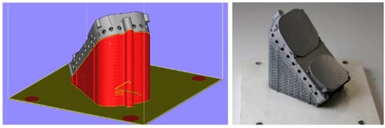
3.2. Design of Support
Support design is indispensable (
Figure 11). Due to the sandwich mirror’s overhanging structures having no casting and molding support constraint, edge warping and collapse easily occur during the forming process. Even severe deformation interruption can happen [
44]. Although some printing techniques have powder or liquid support constraints, they are not strong enough. Moreover, support can also reduce the residual stress of forming parts, and a high-quality support design is vital for the surface roughness and accuracy of parts. However, support design is one of the craft difficulties in AM metal mirrors depending on various factors such as forming processes, printing materials, and parts’ characteristics [
45].
Figure 11. Sketch map of support design [
46].
The support structures can be added through 3D printing software automatically and removed after AM prefabrication using wire cutting and labor-intensive manual removal. However, some support structures are too complex. The optimization of the support is essential. We can optimize support with the help of TO, which reduces materials waste and the difficulty of removal [
47]. The tilt angle prevents the need for added support in sandwich mirrors’ interior and mirror distortion during printing. Some unique structures can be designed to form self-support at a specific angle range to minimize the trouble of removing them later [
48,
49]. The materials of the support should be consistent with mirrors to ensure the mirrors’ accuracy. In addition, the numerical simulation should be used to achieve the intelligent design of the support, and its forming effect should be predicted by heat transfer and force analysis.
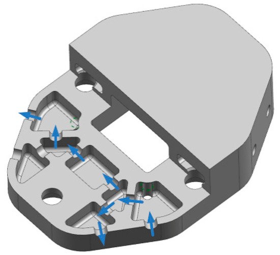
3.3. Connectivity Constraints
The connectivity constraint requires no enclosed voids inside mirrors. For PBF, there should be no residual powder inside parts. Compared to open-back mirrors and arch mirrors, sandwich mirrors are closed-back, so connectivity constraints must be considered in the design stage. In the mirror design, the structure walls are perforated to present complete airflow channels inside the mirror, meeting the connectivity of the airflow and facilitating the removal of residual powder (
Figure 12) [
50,
51,
52]. Finally, ultrasonic cleaning and other methods are used to remove the powder from the interior of the parts altogether.
Figure 12. Schematic diagram of connectivity constraints [
37].
This entry is adapted from the peer-reviewed paper 10.3390/app112210630