The effects of climate change and global warming are arising a new awareness on the impact of our daily life. Power generation for transportation and mobility as well as in industry is the main responsible for the greenhouse gas emissions. Indeed, currently, 80% of the energy is still produced by combustion of fossil fuels; thus, great efforts need to be spent to make combustion greener and safer than in the past. For this reason, a review of the most recent gas turbines combustion strategy with a focus on fuels, combustion techniques, and burners is presented here. A new generation of fuels for gas turbines are currently under investigation by the academic community, with a specific concern about production and storage. Among them, biofuels represent a trustworthy and valuable solution in the next decades during the transition to zero carbon fuels (e.g., hydrogen and ammonia). Promising combustion techniques explored in the past, and then abandoned due to their technological complexity, are now receiving renewed attention (e.g., MILD, PVC), thanks to their effectiveness in improving the efficiency and reducing emissions of standard gas turbine cycles. Finally, many advances are illustrated in terms of new burners, developed for both aviation and power generation. This overview points out promising solutions for the next generation combustion and opens the way to a fast transition toward zero emissions power generation.
- combustion
- hydrogen
- ammonia
- SAF
- MILD combustion
- RQL
- Lean Combustion
- Emulsion
1. Introduction
2. Fuels
2.1. Sustainable Biofuels
2.2. Hydrogen
| Property | Hydrogen | Methane | Kerosene |
|---|---|---|---|
| Density (kg/m3) | 0.0824 | 0.651 | 780 |
| Flammability limits (volume % in air) | 4–75 | 5.5–15 | 0.7–5 |
| Stoichiometric flame velocity (m/s) | 1.85 | 0.40 | 0.49 |
| Stoichiometric adiabatic flame temperature (K) | 2480 | 2226 | 2366 |
| Lower Heating Value (MJ/kg) | 119.7 | 50.0 | 43.1 |
| Lower Heating Value (MJ/Nm3) | 9.9 | 32.6 | - |
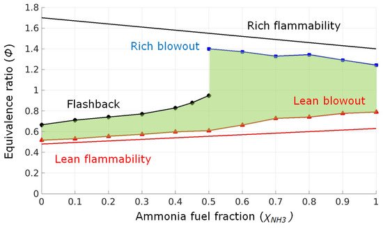
2.3. Ammonia

2.4. Emulsions
3. Combustion Techniques
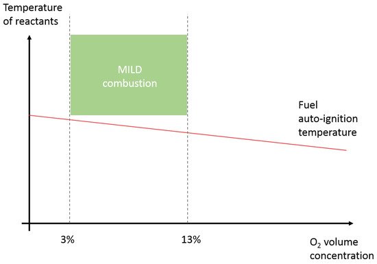
3.1. MILD
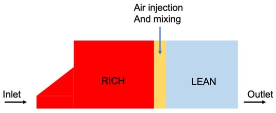
3.2. RQL
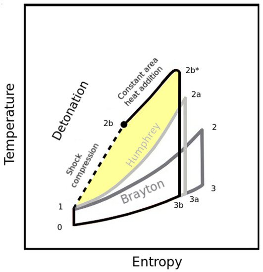
3.3. Pressure Gain Combustion
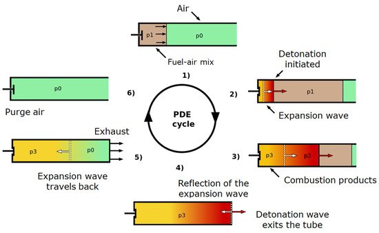
3.3.1. Pulse Detonation Engine (PDE)
3.3.2. Rotating Detonation Engine (RDE)
3.3.3. Wave Rotor Combustors (WRC)
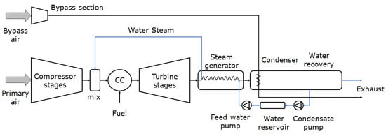
3.4. Steam Injection
4. Burners
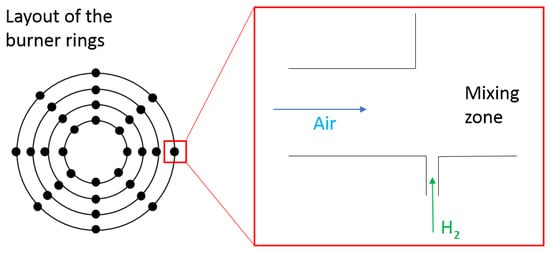
4.1. Micro-Mixer
4.2. LEAF (Lean Azimuthal Flame)
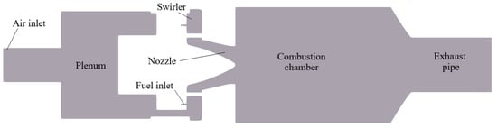
4.3. PRECCINSTA
4.4. TUB Swirled Stabilized Burner
This entry is adapted from the peer-reviewed paper 10.3390/en14206694
References
- IRENA-International Renewable Energy Agency. Global Renewable Outlook: Energy Transformation 2050; IRENA: Abu Dhabi, United Arab Emirates, 2020.
- International Energy Agency (IEA). Aviation; IEA: Paris, France, 2020.
- Carbon Offsetting and Reduction Scheme for International Aviation (CORSIA). Available online: https://www.icao.int/environmental-protection/CORSIA (accessed on 3 August 2021).
- Standard Specification for Aviation Turbine Fuel Containing Synthesized Hydrocarbons. Available online: https://www.astm.org/Standards/D7566.htm (accessed on 3 August 2021).
- International Energy Agency (IEA). Are Aviation Biofuels Ready for Take Off? IEA: Paris, France, 2019.
- International Energy Agency (IEA). Global Energy & CO2 Status Report 2019; IEA: Paris, France, 2019.
- International Energy Agency (IEA). Global Energy Review 2020—The Impacts of the COVID-19 Crisis on Global Energy Demand and CO2 Emissions; IEA: Paris, France, 2020.
- International Energy Agency (IEA). Global Energy Review 2021—Assessing the Effects of Economic Recoveries on Global Energy Demand and CO2 Emissions in 2021; IEA: Paris, France, 2021.
- Shafiee, S.; Topal, E. When will fossil fuel reserves be diminished? Energy Policy 2009, 37, 181–189.
- Dena-German Energy Agency. Available online: https://www.dena.de/en/newsroom/news/2019/global-alliance-powerfuels-promotes-more-alternative-fuels-in-aviation/ (accessed on 3 August 2021).
- Lee, D.S.; Fahey, D.W.; Forster, P.M.; Newton, P.J.; Wit, R.C.N.; Lim, L.L.; Owen, B.; Sausen, R. Aviation and global climate change in the 21st century. Atmos. Environ. 2009, 43, 3520–3537.
- Reichel, T.G.; Terhaar, S.; Paschereit, C.O. Flashback Resistance and Fuel—Air Mixing in Lean Premixed Hydrogen Combustion. J. Propuls. Power 2018, 34, 690–701.
- Wang, M.; Zhong, Y.; Deng, K. Experiment investigation of the effects of hydrogen content on the combustion instability of methane/hydrogen lean premixed swirl flames under different acoustic frequency ranges. AIP Adv. 2019, 9, 045206.
- Æsøy, E.; Aguilar, J.G.; Wiseman, S.; Bothien, M.R.; Worth, N.A.; Dawson, J.R. Scaling and prediction of transfer functions in lean premixed H2/CH4-flames. Combust. Flame 2020, 215, 269–282.
- Indlekofer, T.; Ahn, B.; Kwah, Y.H.; Wiseman, S.; Mazur, M.; Dawson, J.R.; Worth, N.A. The effect of hydrogen addition on the amplitude and harmonic response of azimuthal instabilities in a pressurized annular combustor. Combust. Flame 2021, 228, 375–387.
- Beita, J.; Talibi, M.; Sadasivuni, S.; Balachandran, R. Thermoacoustic Instability Considerations for High Hydrogen Combustion in Lean Premixed Gas Turbine Combustors: A Review. Hydrogen 2021, 2, 33–57.
- Pyo, Y.; Kim, D.; Kim, S.K.; Cha, D.J. Numerical investigation on combustion instability modeling in a lean premixed gas turbine combustor combining finite element analysis with local flame transfer function. J. Mech. Sci. Technol. 2019, 33, 5547–5559.
- Dunn-Rankin, D. Lean Combustion: Technology and Control; Academic Press: Cambridge, MA, USA, 2011.
- Engineering ToolBox, Fuels-Higher and Lower Calorific Values. Available online: https://www.engineeringtoolbox.com (accessed on 1 October 2021).
- Kojima, Y. A Green Ammonia Economy. NH3-Association. 2013. Available online: https://nh3fuelassociation.org/wp-content/uploads/2013/10/nh3fcx-yoshitsugu-kojima.pdf (accessed on 1 October 2021).
- Frigo, S.; Gentili, R.; De Angelis, F. Further insight into the possibility to fuel a SI engine with ammonia plus hydrogen. In Proceedings of the SAE/JSAE 20th Annual Small Engine Technology Conference and Exhibition, Pisa, Italy, 18–20 November 2014.
- Koike, M.; Miyagawa, H.; Suzuoki, T.; Ogasawara, K. Ammonia as a hydrogen energy carrier and its application to internal combustion engines. J. Combust. Soc. Jpn. 2016, 58, 99–106.
- Khateeb, A.A.; Guiberti, T.F.; Zhu, X.; Younes, M.; Jamal, A.; Roberts, W.L. Stability limits and exhaust NO performances of ammonia-methane-air swirl flames. Exp. Therm. Fluid Sci. 2020, 114, 110058.
- Franco, M.C.; Rocha, R.C.; Costa, M.; Yehia, M. Characteristics of NH3/H2/air flames in a combustor fired by a swirl and bluff-body stabilized burner. Proc. Combust. Inst. 2021, 4, 5129–5138.
- Khateeb, A.A.; Guiberti, T.; Zhu, X.; Younes, M.; Jamal, A.; Roberts, W. Stability limits and NO emissions of technically-premixed ammonia-hydrogen-nitrogen-air swirl flames. Int. J. Hydrogen Energy 2020, 45, 22008–22018.
- Okafor, E.C.; Tsukamoto, M.; Hayakawa, A.; Somarathne, K.K.A.; Kudo, T.; Tsujimura, T. Influence of wall heat loss on the emission characteristics of premixed ammonia-air swirling flames interacting with the combustor wall. Proc. Combust. Inst. 2020, 4, 5139–5146.
- Khateeb, A.A.; Guiberti, T.; Wang, G.; Boyette, W.R.; Younes, M.; Jamal, A.; Roberts, W. Stability limits and NO emissions of premixed swirl ammonia-air flames enriched with hydrogen or methane at elevated pressures. Int. J. Hydrogen Energy 2021, 21, 11969–11981.
- Thomas, G.O. Flame acceleration and the development of detonation in fuel-oxygen mixtures at elevated temperatures and pressures. J. Hazard. Mater. 2009, 163, 783–794.
- Thomas, G.O.; Oakley, G.; Bambrey, R. An experimental study of flame acceleration and deflagration to detonation transition in representative process piping. Process Saf. Environ. Prot. 2010, 88, 75–90.
- Han, W.; Shan, S.; Du, Z. Calculation of thermodynamic properties for a new propellant acetylene-ammonia. Chin. J. Energ. Mater. 2014, 22, 161–164.
- Robin, M.R.; Brogan, T.; Cardiff, E. An ammonia microresistojet (MRJ) for micro satellites. In Proceedings of the 44th AIAA/ASME/SAE/ASEE Joint Propulsion Conference, Hartford, CT, USA, 21–23 July 2008.
- De Giorgi, M.G.; Fontanarosa, D.; Ficarella, A.; Pescini, E. Effects on performance, combustion and pollutants of water emulsified fuel in an aeroengine combustor. Appl. Energy 2020, 260, 114263.
- Baena-Zambrana, S.; Repetto, S.L.; Lawson, C.P.; Lam, J.K.W. Behaviour of water in jet fuel—A literature review. Prog. Aerosp. Sci. 2013, 60, 35–44.
- Pourhoseini, S.H.; Yaghoobi, M. Effect of water–Kerosene emulsified fuel on radiation, NOx emission and thermal characteristics of a liquid burner flame in lean combustion regime. J. Braz. Soc. Mech. Sci. Eng. 2018, 40, 408.
- Fontanarosa, D.; De Giorgi, M.G.; Ciccarella, G.; Pescini, E.; Ficarella, A. Combustion performance of a low NOx gas turbine combustor using urea addition into liquid fuel. Fuel 2021, 288, 119701.
- Kobayashi, H.; Hayakawa, A.; Somarathne, K.D.K.A.; Okafor, E.C. Science and technology of ammonia combustion. Proc. Combust. Inst. 2019, 37, 109–133.
- Noor, M.M.; Wandel, A.P.; Yusaf, T.F. MILD Combustion: A Technical Review towards Open Furnace Combustion. In Proceedings of the 2nd Malaysian Postgraduate Conference, Bond University, Gold Coast, QLD, Australia, 7–9 July 2012; pp. 79–100.
- Noor, M.M.; Wandel, A.P.; Yusaf, T. A review of mild combustion and open furnace design consideration. Int. J. Automot. Mech. Eng. 2012, 6, 730–754.
- Ingenito, A.; Agresta, A.; Andriani, R.; Gamma, F. RQL Combustion as an Effective Strategy to NOx Reduction in Gas Turbine Engines. In Proceedings of the ASME International Mechanical Engineering Congress and Exposition, Montreal, QC, Canada, 14–20 November 2014.
- Demayo, T.N.; Leong, M.Y.; Samuelsen, G.S.; Holdeman, J.D. Assessing Jet-Induced Spatial Mixing in a Rich, Reacting Crossflow. J. Propuls. Power 2003, 19, 14–21.
- Mattingly, J.D.; Heiser, W.H.; Pratt, D.T. Aircraft Engine Design, 2nd ed.; American Institute of Aeronautics and Astronautics, Inc.: Reston, VA, USA, 2008.
- Hutchins, T.E.; Metghalchi, M. Energy and Exergy Analyses of the Pulse Detonation Engine. J. Eng. Gas Turbines Power 2003, 125, 1075–1080.
- Azami, M.H.; Savill, M. Pulse Detonation Assessment for Alternative Fuels. Energies 2017, 10, 369.
- Blanco, G.M. Numerical Modelling of Pressure Rise Combustion for Reducing Emissions of Future Civil Aircraft; Cranfield University: Cranfield, UK, 2014.
- Nikitin, V.F.; Dushin, V.R.; Phylippov, Y.G.; Legros, J.C. Pulse detonation engines: Technical approaches. Acta Astronaut. 2009, 64, 281–287.
- Panicker, P.K.; Wilson, D.R.; Lu, F.K. Operational Issues Affecting the Practical Implementation of Pulsed Detonation Engines. In Proceedings of the 14th AIAA/AHI Space Planes and Hypersonic Systems and Technologies Conference, Canberra, Australia, 6–9 November 2006.
- New, T.; Panicker, P.; Chui, K.; Tsai, H.; Lu, F. Experimental Study on Deflagration-to-Detonation Transition Enhancement Methods in a PDE. In Proceedings of the 14th AIAA/AHI Space Planes and Hypersonic Systems and Technologies Conference, Canberra, Australia, 6–9 November 2006.
- Panicker, P.K.; Li, J.-M.; Lu, F.K.; Wilson, D.R. Development of a Compact Liquid Fueled Pulsed Detonation Engine with Predetonator. In Proceedings of the 45th AIAA Aerospace Sciences Meeting and Exhibit, Reno, NV, USA, 8–11 January 2007.
- Li, C.; Kailasanath, K. Detonation Initiation in Pulse Detonation Engines. In Proceedings of the 41st Aerospace Sciences Meeting and Exhibit, Reno, NV, USA, 6–9 January 2003.
- Kaemming, T. Integrated Vehicle Comparison of Turbo-Ramjet Engine and Pulsed Detonation Engine. J. Eng. Gas Turbines Power 2003, 125, 257–262.
- Gulen, S. Pressure gain combustion advantage in land-based electric power generation. J. Glob. Power Propuls. Soc. 2017, 1, 288–302.
- Debnath, P.; Pandey, K.M. Numerical analysis of detonation combustion wave in pulse detonation combustor with modified ejector with gaseous and liquid fuel mixture. J. Therm. Anal. Calorim. 2020, 145, 3243–3254.
- Elhawary, S.; Aminuddin, S.; Wahid, M.A.; Ghazali, A.D. Experimental study of using biogas in Pulse Detonation Engine with hydrogen enrichment. Int. J. Hydrogen Energy 2020, 45, 15414–15424.
- Garan, N.; Djordjevic, N. Experimental and low-dimensional numerical study on the application of conventional NOx reduction methods in pulse detonation combustion. Combust. Flame 2021, 233, 111593.
- Djordjevic, N.; Hanraths, N.; Gray, J.; Berndt, P.; Moeck, J. Numerical Study on the Reduction of NOx Emissions From Pulse Detonation Combustion. J. Eng. Gas Turbines Power 2018, 140, 041504.
- Nordeen, C.A.; Schwer, D.; Schauer, F.; Hoke, J.; Cetegen, B.; Barber, T. Thermodynamic modeling of a rotating detonation engine. In Proceedings of the 49th AIAA Aerospace Sciences Meeting, Toyama, Japan, 25–27 October 2016.
- Sousa, J.; Paniagua, G.; Morata, E.C. Thermodynamic analysis of a gas turbine engine with a rotating detonation combustor. Appl. Energy 2017, 195, 247–256.
- Ma, J.Z.; Luan, M.-Y.; Xia, Z.J.; Wang, J.P.; Zhang, S.J.; Yao, S.B.; Wang, B. Recent Progress, Development Trends, and Consideration of Continuous Detonation Engines. AIAA J. 2020, 58, 4976–5035.
- Anand, V.; Gutmark, E. Rotating detonation combustors and their similarities to rocket instabilities. Prog. Energy Combust. Sci. 2019, 73, 182–234.
- Stoddard, W.; Anand, V.; Driscoll, R.; Dolan, B.; St George, A.; Villalva, R. Experimental characterization of centerbodiless RDE emissions. In Proceedings of the 55th AIAA Aerospace Sciences Meeting, Grapevine, TX, USA, 9–13 January 2017.
- Stoddard, W.A.; Gutmark, E.J. Numerical investigation of centerbodiless RDE design variations. In Proceedings of the 53rd AIAA AerospacE Sciences Meeting, Kissimmee, FL, USA, 5–9 January 2015.
- Stoddard, W.A.; Gutmark, E.J. Numerical Investigation of expanded and stepped centerbodiless RDE designs. In Proceedings of the 51st AIAA/SAE/ASEE Joint Propulsion Conference, Orlando, FL, USA, 27–29 July 2015.
- Schwer, D.A.; Kailasanath, K. Characterizing NOx emissions for air-breathing rotating detonation engines. In Proceedings of the 52nd AIAA/SAE/ASEE Joint Propulsion Conference, Salt Lake City, UT, USA, 25–27 July 2016.
- Akbari, P.; Szpynda, E.; Nalim, R. Recent Developments in Wave Rotor Combustion Technology and Future Perspectives: A Progress Review. In Proceedings of the 43rd AIAA/ASME/SAE/ASEE Joint Propulsion Conference & Exhibit, Cincinnati, OH, USA, 8–11 July 2007.
- Nalim, M.R.; Paxson, D.E. A Numerical Investigation of Premixed Combustion in Wave Rotors. ASME J. Eng. Gas Turbines Power 1997, 119, 668–675.
- Jagannath, R.; Bane, S.P.; Nalim, R.M. Wave Rotor Combustor Turbine Model Development. In Proceedings of the 51st AIAA/SAE/ASEE Joint Propulsion Conference, Orlando, FL, USA, 27–29 July 2015.
- Matsutomi, Y.; Meyer, S.; Wijeyakulasuriya, S.; Izzy, Z.; Nalim, M.R.; Shimo, M.; Kowalkowski, M.; Snyder, P. Experimental Investigation on the Wave Rotor Constant Volume Combustor. In Proceedings of the 46th AIAA/ASME/SAE/ASEE Joint Propulsion Conference & Exhibit, Nashville, TN, USA, 25–28 July 2010.
- Tüchler, S.; Copeland, C.D. Experimental results from the Bath μ-wave rotor turbine performance tests. Energy Convers. Manag. 2019, 189, 33–48.
- Tüchler, S.; Copeland, C.D. Numerical optimisation of a micro-wave rotor turbine using a quasi-two-dimensional CFD model and a hybrid algorithm. Shock Waves 2021, 31, 271–300.
- Nalim, M.R.; Snyder, P.H.; Kowalkowski, M. Experimental Test, Model Validation, and Viability Assessment of a Wave-Rotor Constant-Volume Combustor. J. Propuls. Power 2017, 33, 163–175.
- Li, J.; Gong, E.; Yuan, L.; Wei, L.; Zhang, K. Experimental Investigation on Pressure Rise Characteristics in an Ethylene Fuelled Wave Rotor Combustor. Energy Fuels 2017, 31, 10165–10177.
- Göke, S.; Paschereit, C.O. Influence of Steam Dilution on NOx Formation in Premixed Natural Gas and Hydrogen Flames. In Proceedings of the 50th AIAA Aerospace Sciences Meeting including the New Horizons Forum and Aerospace Exposition, Nashville, TN, USA, 9–12 January 2012.
- Schmitz, O.; Kaiser, S.; Klingels, H.; Kufner, P.; Obermüller, M.; Henke, M.; Zanger, J.; Grimm, F.; Schuldt, S.; Marcellan, A.; et al. Aero Engine Concepts Beyond 2030: Part 3—Experimental Demonstration of Technological Feasibility. J. Eng. Gas Turbines Power 2021, 143, 021003.
- Schmitz, O.; Klingels, H.; Kufner, P. Aero Engine Concepts Beyond 2030: Part 1—The Steam Injecting and Recovering Aero Engine. J. Eng. Gas Turbines Power 2021, 143, 021001.
- Kaiser, S.; Schmitz, O.; Klingels, H. Aero Engine Concepts Beyond 2030: Part 2—The Free-Piston Composite Cycle Engine. J. Eng. Gas Turbines Power 2021, 143, 021002.
- Pouzolz, R.; Schmitz, O.; Klingels, H. Evaluation of the Climate Impact Reduction Potential of the Water-Enhanced Turbofan (WET) Concept. Aerospace 2021, 8, 59.
- Tekin, N.; Ashikaga, M.; Horikawa, A.; Funke, H. Enhancement of fuel flexibility of industrial gas turbines by development of innovative hydrogen combustion systems. Rep.-Gas Turbines 2019, 2, 1–6.
- de Oliveira, P.M.; Fredrich, D.; De Falco, G.; El Helou, I.; D’Anna, A.; Giusti, A.; Mastorakos, E. Soot-Free Low-NOx Aeronautical Combustor Concept: The Lean Azimuthal Flame for Kerosene Sprays. Energy Fuels 2021, 35, 7092–7106.
- Meier, W.; Boxx, I.; Stöhr, M.; Carter, C.D. Laser-based investigations in gas turbine model combustors. Exp. Fluids 2010, 49, 865–882.
- Kelsall, G.; Troger, C. Prediction and control of combustion instabilities in industrial gas turbines. Appl. Therm. Eng. 2004, 24, 11–12.
- Meier, W.; Weigand, P.; Duan, X.R.; Giezendanner-Thoben, R. Detailed characterization of the dynamics of thermoacoustic pulsations in a lean premixed swirl flame. Combust. Flame 2007, 150, 2–26.
- Roux, S.; Lartigue, G.; Poinsot, T.; Meier, U.; Bérat, C. Studies of mean and unsteady flow in a swirled combustor using experiments, acoustic analysis, and large eddy simulations. Combust. Flame 2005, 141, 40–54.
- Chterev, I.; Boxx, I. Flame Topology and Combustion Instability Limits of Lean Premixed Hydrogen Enriched Flames. In Proceedings of the 27th International Colloquium on the Dynamics of Explosions and Reactive Systems (ICDERS), Beijing, China, 28 July–2 August 2019.
- Chterev, I.; Boxx, I. Effect of hydrogen enrichment on the dynamics of a lean technically premixed elevated pressure flame. Combust. Flame 2021, 225, 149–159.
- Reichel, T.G.; Goeckler, K.; Paschereit, O. Investigation of Lean Premixed Swirl-Stabilized Hydrogen Burner With Axial Air Injection Using OH-PLIF Imaging. J. Eng. Gas Turbines Power 2015, 137, 111513.