Your browser does not fully support modern features. Please upgrade for a smoother experience.
Please note this is an old version of this entry, which may differ significantly from the current revision.
Subjects:
Energy & Fuels
Integrated photovoltaic-fuel cell (IPVFC) system uses photovoltaics and fuel cells to majorly generate power and hydrogen, using solar energy as the prime mover. IPVFC amongst other integrated energy generation methodologies are renewable and clean energy technologies that have received diverse research and development attentions over the last few decades due to their potential applications in a hydrogen economy.
- solar energy
- photovoltaic-fuel cell system
- power generation
- hydrogen economy
- photovoltaics
- fuel cells
1. Design Methodologies, Composition and Configurations
IPVFC systems have flexible configurations to accommodate different types of components which is an undeniable engineering advantage. The autonomous operation of the system is facilitated by an energy management system, which provides a logical algorithm that controls the flow of energy in the system [20]. The modularity in the design of IPVFC systems implies that they are easily scalable [21]. Thus, the system can be configured to meet users’ requirements and satisfy specific use cases. Notwithstanding, to contextualize this study, there are four categories of design methodologies of IPVFC systems, although there could be variations in the composition of a category depending on the use case. The following are brief descriptions of the categories:
-
Category 1: PV, fuel cell and batteries can supply power to the load.
-
Category 2: PV and fuel cell supplies power to the battery bank/supercapacitor so that it can supply power to the load.
-
Category 3: Combined heat and power (CHP) design in which the PV is replaced with photovoltaic-thermal (PV/T) component.
-
Category 4: Compact design that replaces proton exchange membrane electrolyser (PEME) and proton exchange membrane fuel cell (PEMFC) components with a unitized regenerative proton exchange membrane fuel cell (URPEMFC) component.
The first category of IPVFC systems is typified by the configuration in Figure 1. This design methodology for power generation is composed of a photovoltaic module, DC/DC converter for the photovoltaic, battery, step-down converter for electrolyser, electrolyser, fuel cell, step-up for the fuel cell, and a DC/AC inverter [20]. In this configuration, a DC/DC converter is used to connect the PV modules, electrolyser, fuel cell and battery to the DC-bus bar. A DC/AC inverter is connected to the DC-bus bar to change the DC to AC for AC loads [22]. Integrating PV modules with batteries and FC stacks makes the integrated system more sustainable because the system can reliably satisfy load requirements, even in the absence of solar radiation [23]. This category may use a proton exchange membrane electrolyser to generate hydrogen and proton exchange membrane fuel cell to convert the stored hydrogen to meet power demanded [24]. PEMFC has a high energy density per unit area, zero greenhouse gas emission, modular design, noiseless operation, limited moving parts and it is not limited by the Carnot efficiency [25,26]. This configuration is suitable for buildings, stationary applications, grid-connected systems, and mobile applications. As a variation of this design, the system can be configured so that batteries can provide the basic power while peaks in demand for power can be met with the fuel cell. This feature is crucial in achieving optimal operational efficiency of renewable energy-based smart grids since the intermittency of solar energy could lead to excess electricity generation or shortage of it.
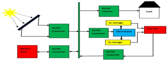
Figure 1. Schematic diagram of an IPVFC system including a PV, battery, electrolyser, and fuel cell.
The second category of IPVFC systems is shown in Figure 2. This is more suitable for automotive and unmanned aerial vehicle (UAV) applications. Integrated fuel cell hybrid electric vehicles and fuel cell electric vehicles are actively being investigated as potential replacements for internal combustion engines in the automotive industry [27,28], and the trend will likely continue onwards because the automotive sector is a major contributor of emissions [29].
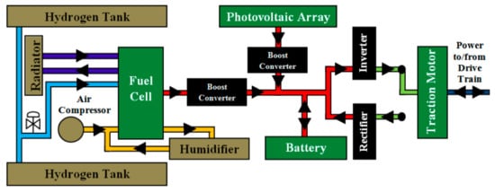
Figure 2. Schematic diagram of IPVFC system as power source for automotive applications [36].
In this configuration, a PV module and an FC stack charge the battery bank which provides tractive power to drive the entire system. This configuration provides a more stable power source compared to configurations in which electrical energy is supplied to the load directly from the PV module. For shorter periods, batteries can supply constant direct current if charged, while fuel cells can provide direct current to keep the battery charged for a longer timeframe using hydrogen. In this category, hydrogen may be produced within or outside the system or obtained from hydrogen filling stations to reduce the weight of the electrolyser from the total weight of the system.
Lead acid batteries [24] have achieved technological maturity and most IPVFC systems use it. Nonetheless, Li-ion batteries are uniquely compatible with renewable energy resources [18], and their utilization will continue to increase until a more efficient and safer battery cell is innovated. Supercapacitors (SC) have high-power density, fast dynamics and a relatively longer lifetime compared to batteries, but they discharge fast. Supercapacitors have been used in this configuration to assist stabilize the power supplied by a PV module and a PEMFC stack [30]. Thus, combining batteries and SC have been reported to be beneficial for improving the reliability of the system [31,32]. PV modules and FC stacks are used without batteries/SC to reduce the overall cost of the system when it is not necessary to store electrical energy [33]. Boost converters are used to adapt the low DC from the PV and the FC to a regulated bus bar DC [34]. The boosting and inversion of unregulated low-voltage output from the FC can be efficiently achieved at a low cost and compactness using a boost-inverter with a bidirectional backup battery storage [35]. A bidirectional converter and a boost converter can also be combined to manage the flow of current in IPVFC systems so that the current/voltage output of FC can be regulated by a boost converter, whilst the bidirectional converter regulates the current/voltage from the battery and supercapacitor [32]. Bus bars enable the electrical connection of the components to ensure that the DC sources and the DC supplies are properly integrated to facilitate an effective spatial topology of IPVFC systems.
The third category of IPVFC systems uses a photovoltaic-thermal (PV/T) module or solar thermal collectors [37] instead of a PV module to achieve a co-generation system (or combined heat and power (CHP)). Consequently, electricity and hot fluid can be generated as shown in Figure 3. This configuration is predicated on the preconception that harnessing the thermal energy from the PV module could lead to improved energy and exergy efficiency of the first category of IPVFC system. Further design variation of this category involves harnessing the waste heat from the PEME and PEMFC to perform additional thermal work such as heating of air, water, or other fluids since they operate between 70 and 100 °C.
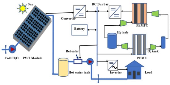
Figure 3. Schematic diagram of an IPVFC system including a PV/T, battery, electrolyser and fuel cell [38].
The fourth category of design methodology of IPVFC systems replaces the electrolyser and fuel cell components with a unitized regenerative fuel cell. The electrolyser and fuel cell exist as separate components in categories 1, 2 and 3. Category four unifies the electrolyser and fuel cell as a URPEMFC system [39], so that it can perform the functions of an electrolyser and a fuel cell [40] as shown in Figure 4. This intimate unification implies lesser cost and complexity compared to discrete reversible proton exchange membrane fuel cell (DRPEMFC) systems in which the components exist separately.
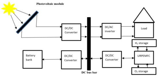
Figure 4. Block diagram of an integrated IPVFC system in which the electrolyser and fuel cell components are replaced with a unitized regenerative fuel cell system [41].
In addition, to using PEMFC, solid oxide fuel cell (SOFC) has been proposed to build IPVFC systems as a potential replacement for diesel generators. This can use a liquid fuel, a solid fuel, or a natural gas reformer to process the fuel [8]. The reformation process may include a water gas shift reaction [42] to produce hydrogen that can be utilized to generate power using PEMFC component. Tejwani and Suthar [43] investigated the use of PV and SOFC components for power generation using P-Q control approach. A 50 kW PV array served as the basic power source while a 30 kW SOFC acted as the backup. SOFC can be integrated with micro-turbine [9,44] and/or thermophotovoltaic (TPV) module [7] for co-generation or multi-generation systems because of the high operating temperature of SOFC. As an example, Arsalis et al. [45] integrated 70 kW PV arrays with 137.5 kW SOFC for CHP application. In addition, a TPV component can be used to recover exhaust heat from high temperature of SOFC (800–1000 °C) for power generation regardless of the weather conditions, unlike solar photovoltaic systems that depend on solar radiation [46]. Systems composed of TPV and SOFC components could evolve considering the renewed interests in TPV applications [47,48]. Figure 5 shows a configuration in which waste heat from the SOFC component can be recovered for power generation using a thermophotovoltaic component. Although the integration of SOFC with PV or TPV could result in a multi-generation system, the steam reform process of solid, liquid, or gaseous fuels produces carbon dioxide unlike the use of PEME in conjunction with PEMFC or URPEMFC which are cleaner alternatives. Direct ammonia fuel cells (AFC) [49] is another type of fuel cell that has been proposed for IPVFC systems, although it has a complex fuel processing characteristics compared to a PEMFC component.
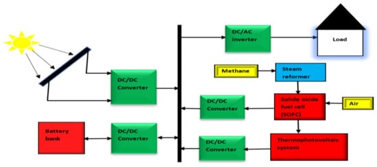
Figure 5. Block diagram of an IPVFC system including SOFC and TPV components.
An essential component which applies to all the categories of IPVFC systems is the maximum power point tracker (MPPT). It ensures that the maximum power is extracted from PV modules based on the available solar radiations, regardless of weather conditions. Examples of MPPT algorithm and implementation methodologies are perturb and observe method, incremental conductance method, short-circuit current method, open circuit voltage method, fuzzy logic controllers, and artificial neural network controllers [50,51]. Karami et al. [52] used MPPT and compensators to extract the maximum power from the PV modules and FCs as the demand for power varied with time. Padmanaban et al. [53] demonstrated how the Jaya-based MPPT method can be used to track the MPP of PV modules for an IPVFC system. Energy management system (EMS) or Power management system (PMS) is also necessary for controlling the energy flow in an integrated IPVFC system. Equally important for optimal operating conditions of IPVFC systems are the ancillaries and health monitoring of components such as compressors, pumps, fan/blowers, charge controller for the batteries, as well as sensors to measure temperature, pressure, mass flow rates, and humidity. The compressors are used to store gases from the PEME in tanks or for feeding the reactant gases into the fuel cell component as illustrated in Figure 3. Pumps are required to feed water into the electrolyser or PV/T components. Fans/blowers are used to cool the temperature of the components such as the batteries, PEME and PEMFC. In the design phase of IPVFC systems, the power consumed by the ancillaries are discounted from the power produced by the system. The deductions are done to ensure that the power consumed by the actual loads and the ancillaries are considered during capacity sizing of an IPVFC system. Touati et al. [54] assumed that 20% of a 12 kW installed capacity is consumed by the ancillaries to cool the PEMFC and pressurize gases. To enhance the reliability of the system, power supply to the ancillaries were configured so that the ancillaries for the PEMFC are not connected to the PV modules since it is subject to intermittency; although the ancillaries of the PEME can be connected to the PV modules since electrolysis can take place during the day.
Sizing of IPVFC systems depends on the load profile of the application [19]. Accurate sizing is a major challenge with IPVFC system deployment due to the intermittency of solar radiation. The interrelationships between the dynamic load profile, power generation, hydrogen generation and solar radiation availability require reliable control strategies [55]. During operation of an IPVFC system, the amount of hydrogen consumed by an FC stack is proportional to the power drawn from the FC stacks; while the hydrogen produced from the electrolyser is proportional to the power supplied to the electrolyser [56]. The power available for hydrogen production depends on the solar availability, the power consumed by the loads, the power consumed by the ancillaries, the power used for charging batteries/SC components and the power lost due to conversion losses. Hourly load current can be multiplied by the number of hours of operation of an IPVFC system to get the daily load [55]. This means that the ampere-hour for all the load components/ancillaries can be added to estimate the expected capacity of the system.
Table 1 summarizes some studies to highlight the design intents and compositions of some IPVFC systems.
Within the categories of IPVFC systems, different types of PV cells, fuel cell and electrolyser can be used. For instance, Lead acid [24], Li-ion [18] batteries and supercapacitors [30] were considered as potential energy storage components for IPVFC systems. Hydrogen can be stored as a compressed gas in tanks [20] or in metal hydride storage [17]. Alkaline electrolyser [18] or PEME [57] can be used as a source of hydrogen. PEME is adapted to compensate for the possible fluctuations of solar energy because of its fast response to current fluctuations. The US Department of Energy found out that a PEME produces hydrogen at 99.99% of purity level for less than USD 10/kg. This high level of purity of hydrogen is suitable for the operation of PEMFC. The current density is 4–5 times that of an alkaline electrolyser and it uses no corrosive electrolyte unlike alkaline electrolyser, although alkaline electrolyser is more matured technologies [58,59]. PEMFC is widely used for IPVFC applications since it uses hydrogen [57] which can be generated from water electrolysis using excess electricity from the PV array. Polycrystalline solar cells [18] have higher conversion efficiency than monocrystalline solar cells.
2. Current and Emerging Applications of IPVFC Systems
4.1. Application of IPVFC Systems in Microgrids
Microgrids are important in the utilization of renewable energy resources because they can facilitate distributed energy infrastructures in which energy can be generated close to the end-users. Ghenai and Bettayeb [77] studied the integration of a 500 kW PV array and a 100 kW PEMFC with the grid to supply power to a University building in Sharjah, United Arab Emirate. The demand was met although 26% of the power consumed was purchased from the grid. The supply mix includes 42% of the power from the PV array and 32% from the PEMFC stack while 5% of the annual output was sold to the grid. Sharma and Mishra [78] proposed a dynamic power management scheme for stand-alone micro-grid in which all the sources, energy storage and loads were connected to a DC link. Hidaka and Kawahara [119] asserted that efficient application of the grid-connected PV arrays for domestic applications requires energy storage which can be facilitated by using solar hydrogen as energy vector to compensate for the fluctuations in power generation due to the intermittency of solar radiation and ambient temperature.
4.2. Off-Grid/Stand-Alone Applications of IPVFC Systems
The dependence of IPVFC systems on solar radiation makes them suitable for remote power sources for autonomous residential applications, telecommunication infrastructure, agro-processing, research activities, sporting facilities and leisure in remote locations. Ulleberg [63] posited that PV arrays, fuel cell and water electrolysis could play a major role in the future stand-alone power systems. Silva et al. [122] conducted a pilot study on the use of an IPVFC system in the National Park of Araguaia, Tocantins-Brazil. Based on their findings, the noiseless and clean attributes make it suitable for distributed generation applications in public spaces such as train stations, zoos, museums, libraries, motor parks/bus stations, markets, etc. This is particularly useful in many underdeveloped countries where public utilities operate without electricity, water, refrigeration of food and drinks, air-conditioning of spaces, lighting, and entertainment. Cordiner et al. [123] analyzed a full year of data collected from six remote off-grid Radio Based Stations (RBS) and found that an IPVFC system can meet 24 h/7 day high quality, autonomous and continuous power supply required by an off-grid RBS, particularly in developing countries where power grids are grossly underdeveloped. Another study by Silva et al. [71] showed that it was feasible to use an IPVFC system for power generation in an isolated community in the Amazon region of Brazil. The system was composed of a PV array of 124 W with 30.1 V, a PEMFC at 5 kW at 48 V; a PEME at 6 kW per Nm3 h−1 of hydrogen produced; and a lead acid battery (220 Ah at 12 V). The study implied that the costs of the components are still high but using a battery for energy storage appeared to be favored since the cost of adding an electrolyser and a fuel cell will increase the cost of the system. Based on economic analysis, a PV-battery system is cheaper than an IPVFC system of similar capacity, but the inclusion of a fuel cell can protect the battery from stresses associated with the depth of discharge, thereby elongating the life of the battery, and reducing the overall replacement costs of the battery.
An IPVFC system can be used in the agricultural sector for all-year-round crop and animal production and agro-processing given that it can be operated under distributed and off-grid modes. This allows farmers to meet short-term needs using PV arrays, batteries/supercapacitors, and long-term needs with an electrolyser and fuel cell stacks. Since solar radiation is abundant during summer, excess electricity can be stored as hydrogen so that power can be supplied during winter when solar intensity usually dwindles. Ganguly et al. [33] studied how an IPVFC system can be used to power a greenhouse in a sustainable manner based on the climatic conditions of Kolkata, India. They used 51 solar PV modules to generate hydrogen with an electrolyser (3.3 kW) and charge a battery bank such that the battery bank and two PEM fuel cell stacks (480 W each) can meet the energy demand. IPVFC systems can be used for desalination to convert seawater, brackish water, or fresh water of unknown quality to potable water as well as generate electricity and hydrogen. A feasibility study of seawater electrolysis using an IPVFC system has been conducted to generate hydrogen and oxygen from salty water instead of using fresh water which is better used for domestic, agricultural, and industrial purposes [80]. The presence of NaCl was reported to enhance hydrogen production and the system also produced fresh water as a by-product. Touati et al. [54] studied the potential application of an IPVFC system to provide a stand-alone power source for a desalination plant.
This entry is adapted from the peer-reviewed paper 10.3390/en14206827
This entry is offline, you can click here to edit this entry!