During the past 40 years, membrane development has been focused on pressure driven processes but the attention in ODMPs, like FO and PRO, has increased in the last decade
[12] since they demonstrate significant promise to leverage the global water-energy nexus
[13]. It is crucial to formulate customized membranes for these technologies since membrane properties such as structural parameters, water permeability and solute permeability affect the overall performance of FO and PRO processes. For instance, asymmetric FO membrane is an essential component to determine the performance of FO-BES where its properties such as mass transfer resistance and proton transfer ability affect the bioenergy production
[8]. Generally, there are two methods to prepare membrane including (1) direct phase inversion, which involves phase inversion of a polymer dope in a non-solvent followed by formation of integrally skinned membranes, and (2) interfacial polymerization (IP), which is utilized to create thin-film composite (TFC) membranes
[14]. Modifications on membrane including its microporous substrate and selective layer have been the main research area to improve the performance of FO and PRO processes. For instance, specific functional compounds or groups have been introduced on the surface of the selective layer to tackle the problems of fouling and low productivity
[15]. In short, a desired osmotic membrane should be thin, highly selective, and antifouling while compatible with the chosen draw solution, produce high water fluxes, decline dissolved solutes, and tolerate mechanical pressures caused by operation conditions
[15][16].
2.1. Concentration Polarization
An osmotic membrane consists of an active layer and a support layer. The former selectively allows movement of solvent molecules but declines at least some dissolved ions whereas the latter with a side bond to the former comprises a phase-inversion sub-layer and an electrospun-fiber sub-layer. Concentration polarization (CP) happens when the salt concentration difference across the active layer is different from the concentration difference of the bulk solutions itself
[17]. Since DS is diluted by the incoming water flux, there is an immediate reduction in the osmotic pressure at the surface of membrane facing the concentrated DS, causing the solute concentration on the other membrane side facing the FS to increase, since the diffusion of water is towards the DS
[18].
Depending on the membrane orientation, these two CP phenomena can happen either on the active layer or on the support layer since the asymmetric membrane is used in the FO process. Although any of the membrane orientations can be used to operate ODMPs, for clarity, the process is said to be in FO mode (also known as AL-FS orientation) given that the active layer faces FS and support layer faces DS. Generally, this mode can be used for any membrane separation process. In contrast, the process is termed as PRO mode (also known as AL-DS orientation) when the active layer faces the DS and the support layer faces the FS. PRO mode is normally used for osmotic power generation
[19].
On the other hand, there are two kinds of CP where the formation of a concentration layer at the membrane surface and in the porous structure of asymmetric membranes is defined as external concentration polarization (ECP) and internal concentration polarization (ICP), respectively
[20]. ECP is usually associated with the concentrations of DS and FS whereas ICP is mainly affected by the support layer structure and thick dense membrane
[4]. The presence of CP can significantly affect the effective osmotic pressure difference (Δπ) across the membrane leading to a sharp decline in water flux and operational performance of FO and PRO processes
[21][22].
In PRO mode operation, water from FS moves into the porous support layer and permeates through the active layer. The salt from FS also enters the support layer however, it cannot pass through the active layer, resulting in an increase of concentration within the support layer, which is called concentrative ICP. In FO mode operation, dilutive ICP takes place when water permeate dilutes the DS within the porous support layer, causing slow solute mass transfer
[23]. ICP could become acute in ODMPs and it cannot be erased by manipulating hydraulic conditions like increasing turbulence or shear force since it happens within the support layer, thus membranes specially designed for ODMPs are desired for applications
[2]. Optimization on porosity, thickness, and tortuosity of the substrate structure is essential for minimizing the severe effects of ICP. For example, an FO membrane that has a highly porous substrate with low tortuosity and a detect-free thin selective layer is the most effective approach to alleviate ICP
[15].
2.2. Membrane Materials
To develop a system with optimal flux, the choice of material to fabricate a membrane is significant because membrane fouling can directly affect the membrane flux. The material selection also depends on the purpose of the membrane since the operational parameters of FO and PRO are quite different. They require different selectivity degrees for the membrane skin layer where FO needs highly selective membranes whereas PRO which targets high power density requires just sufficient salt decline to maintain the driving force and govern concentration polarization
[24]. Furthermore, most conventional FO membranes, which are usually tailored to be porous and thin to lower ICP and structural parameters, will either be damaged or deformed under high pressure of PRO
[14]. This may cause serious leakage of DS and failure towards the entire process
[25]. This indicates that PRO membranes must be robust enough to tolerate the operational hydraulic pressure. Micro-void type support layers that tend to reduce CP can be beneficial for the FO process; however, their applications in PRO are restricted to lower pressure processes since the micro-void structure can easily be collapsed under the effects of high hydraulic pressure
[26].
Early attempts to fabricate FO and PRO specialized membranes were restricted to cellulose triacetate (CTA) and TFC membranes
[25]. Cellulose is the most abundant existing natural polymer and derivatives of cellulose such as cellulose acetate (CA) and CTA are appropriate materials to fabricate membranes due to their good separation, moderate flux, and non-toxicity
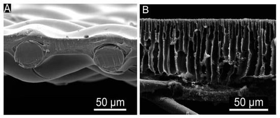
[27]. In order to produce CTA membranes (as demonstrated in
Figure 1A), a dense active layer is formed by casting CTA with an embedded polyester fabric where the thickness of the active layer is minimized to improve the water permeability while maintaining the membrane integrity or contaminant rejection
[15]. However, CTA membranes have restrictions in their application for desalination due to their comparatively low water permeability and solute rejection. Severe CP has been induced in CTA membranes by a sponge-like structure which was initially designed to improve flux
[15]. In addition, cellulose-based materials not only have low stability to pH and temperature but also undergo biodegradation and hydrolysis
[27].
Figure 1. Cross-section SEM micrographs of (
A) commercial CTA-HTI and (
B) TFC membrane. Reproduced with permission from Yip, Tiraferri, Phillip, Schiffman and Elimelech
[16], Copyright (1969) American Chemical Society.
Therefore, enhanced TFC membranes have been developed to keep the high water flux obtained by CTA membranes and to improve the mechanical robustness of the membranes
[25]. This is because highly selective and permeable TFC membranes have high flexibility in structural design with the ability to individually optimize the two membrane layers (selective and substrate layer) for specific needs
[15][28]. Modification on the structure of the support layer significantly reduces ICP while having the dense thin film layer allows great water permeability and salt rejection
[7]. A TFC membrane (as shown in
Figure 1B) generally consists of (1) a very thin polyamide active layer, (2) a polymeric support layer, and (3) a fabric layer for mechanical support
[29]. Some examples of the artificial polymers are polysulfone (PSF), polyether sulfone (PES), polyvinylidene fluoride (PVDF) and polyacrylonitrile (PAN)
[27]. The standard preparation method of TFC membrane layer-by-layer assembly using the microporous substrate obtained through phase inversion and the polyamide layer formed through IP between chloride and amine monomers such as trimesoyl chloride and m-phenylenediamine
[15].
Wang, et al.
[30] had compared the characteristics of CTA and TFC FO membranes provided by Hydration Technologies Innovation (HTI, Albany, NY, USA) and the results are shown in
Table 1. The smaller contact angles indicate a higher hydrophilicity degree, which means permeation of water is easier and higher water flux is expected
[31]. Indeed, higher water flux was observed in TFC membrane compared to CTA membrane under the same operating conditions
[30]. It is noteworthy that in a more recent study by Li, et al.
[32], a self-made TFC membrane in comparison with a commercial CTA-HTI membrane also exhibited higher flux loss due to membrane fouling
[32]. Flux loss is one of the important criteria to be considered for overall flux performance when designing an osmotic membrane system. Nevertheless, higher reverse salt flux was observed with TFC membranes in both studies
[30][32].
Table 1. Comparison of commercial CTA and TFC membrane produced by Hydration Technologies Innovation (HTI, Albany, NY, USA). Adapted with permission from Wang, Tang, Zhu, Dong, Wang and Wu
[30], Copyright (2014), Elsevier B.V.
| Parameters |
Cellulose Triacetate |
Thin-Film Composite |
| Thickness of active layer (µm) |
6.1 ± 2.0 |
4.9 ± 1.1 |
| Thickness of support layer (µm) |
51.4 ± 6.7 |
47.8 ± 2.5 |
| Pore size of SL (µm) |
5.3 ± 1.0 |
3.9 ± 2.0 |
| Contact angle of active layer (°) |
86.0 ± 4.5 |
79.2 ± 6.3 |
| Contact angle of support layer (°) |
72.8 ± 1.9 |
73.8 ± 6.0 |
| Water permeability (A) (L/(m2 h bar)) |
0.70 ± 0.07 |
1.24 ± 0.04 |
| Salt permeability (B) (L/(m2 h)) |
0.53 ± 0.03 |
0.37 ± 0.08 |
| Salt rejection rate (%) |
94.7 ± 0.1 |
97.7 ± 0.5 |
| Water flux |
Lower |
Higher |
| Reverse solute flux |
Lower |
Higher |
In another study
[33], which compared the PRO performance of five different membranes including CTA-HTI, CTA-HTI spiral, CTA-FTS, TFC-FTS, and TFC-Aquaporin (Fluid Technology Solutions (FTS) and Aquaporin A/S are commercial membrane companies), it was found that although TFC membranes have higher flux, CTA membranes with higher pressure stability show higher power densities because the latter with a thicker rejection layer is less likely to be damaged at high pressure while the former is more prone to compaction. To summarize, it is obvious that each material has better performance in different aspects and more comparison studies should be carried out to provide evidence that support the hypothesis of one being better than another.
The development of the membrane materials and synthesis methods has been enhanced by the research and commercial attention on FO and PRO, resulting in the use of other materials
[25]. For instance, a variety of nanomaterials, as shown in
Table 2, has been used to alter the membrane substrates, either only form the active layer, or fabricate the whole thin film nanocomposite (TFN) membranes
[34]. Incorporation of hydrophilic nanomaterials such as carbon-based nanomaterials functionalized with hydrophilic moieties can alleviate ICP by forming higher hydrophilicity, bigger porosity, and lower tortuosity
[35]. Since the synthesis processes for TFC membranes are well established, any discovery on new membrane materials can be scaled up effortlessly for commercialization
[36]. For example, aquaporins, which are water channel membrane proteins, have been incorporated into membrane substrate and this biomimetic Aquaporin membrane has been large scale commercialized for academic and industrial applications
[37]. Nonetheless, it must be noted that there is a limited number of pilot-scale research carried out to apply TFC membranes in commercial-scale FO and PRO processes. More extensive researches at a bigger scale are needed for osmotic membranes to find out their feasibility for a sustainable operation to the point of commercialization despite the promising findings in laboratories.
Table 2. Recent nanostructured osmotic membrane and their experimental performance.
| Type of Nanomaterials |
Nanoparticles Incorporated |
Effects |
Water Flux (Jw, L/m2 h) |
Ref. |
| Unmodified |
Incorporated |
| Carbon nanotubes |
400 ppm sulfonated carbon nanotubes |
|
21.3 ± 2.1 |
29.9 ± 1.6 |
Li, et al. [38] |
| Zeolites |
0.4 wt % modified clinoptilolite |
|
16.3 |
24.61 |
Salehi, et al. [39] |
| Zwitterions |
Poly [3-(N-2-methacryloylxyethyl-N,N-dimethyl)-ammonatopropanesulfonate] (PMAPS) |
|
12.54 |
15.79 |
Lee, et al. [40] |
| Graphene oxide |
0.1% graphene oxide nanosheets |
-
Increase in the hydrophilicity
-
Increase in a surface roughness value
-
Better water permeability
|
7.9 |
14.5 |
Shokrgozar Eslah, et al. [41] |
| Carbon quantum dots |
Na+-functionalized carbon quantum dots |
-
Higher roughness
-
Larger effective surface area
-
Decreased membrane thickness
-
Increased interstitial space among the polyamide chains
|
24.25 ± 2.8 |
34.86 ± 1.41 |
Gai, et al. [42] |
| Metal and metal oxide nanoparticles |
0.5 wt % molybdenum oxide NPs
(MoO3) |
|
~21 |
67 |
Amini, et al. [43] |
| Polyelectrolytes |
Layer-by-layer polyvinylidenefluoride (PVDF) |
|
5.4 |
24.1 |
Gonzales, et al. [44] |
| Metal–organic frameworks |
0.12 w/v % copper 1,4-benzenedicarboxylate nanosheets, CuBDC-NS |
|
18 |
28 |
Dai, et al. [45] |
2.3. Membrane Configurations
In addition to membrane materials, membranes have been fabricated into two membrane configurations based on geometry that is flat sheet and hollow fiber configurations to improve performance such as achieving high water fluxes and superior rejection properties
[46]. Generally, as compared to the hollow fiber membrane, it is easier to engineer a thinner support layer in a flat sheet membrane, thus it has higher water flux and power density
[7]. However, due to the thin support layer and lower packing density, flat sheet membranes are less mechanically stable and more likely to experience structural destructions under pressure, even with a macro-void free support layer
[14]. Compaction due to pressure always negatively affects the properties of the flat sheet membranes, such as increasing the resistance of porous substrates, decreasing the permeability of the selective layers, and enhancing the salt leakage by spacer
[47].
Therefore, recent approaches in developing flat sheet membranes focus on enhancing their mechanical robustness, which is crucial for the PRO applications since it decides the maximum applicable hydraulic pressure. For example, the selective layer of flat sheet membranes is normally post-treated with chemical and physical modification for better mechanical strength
[48]. Another approach to improve the pressure tolerance of flat sheet membranes is by utilizing customized spacers. Membrane with customized tricot fabric spacers was able to tolerate a stable 48 bar hydrostatic pressure for exceeding 10 h and achieve 14.1 W/m
2 at 20.7 bar
[14]. The restrictions of pressure observed in numerous previous PRO research are primarily because of the unsuitable selection of spacer material.
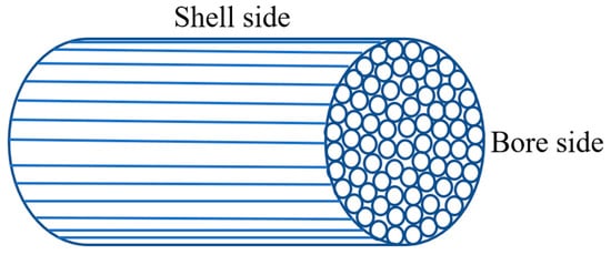
Hollow fiber membranes (as shown in
Figure 2) are tubular-shaped membranes and this configuration provides key benefits including a self-supporting structure and high packing density in membrane modules
[49]. Hollow fiber membranes commonly feature a higher mechanical strength due to their geometrical (circular) structure. The fabric support-free hollow fiber configurations could also give rise to better control of the structural parameters
[49]. Furthermore, the hollow fiber membrane module demonstrates higher efficiency (flux) of mass transfer compared to the flat-sheet (spiral-wound) module
[50]. Wang, et al.
[51] discovered that contact angles of FO hollow fiber membranes were much smaller than the commercial flat sheet membranes suggesting that they have higher hydrophilicity and lower fouling tendency. Besides, Chou, Wang and Fane
[47] reported much lower specific reverse salt flux in the hollow fiber membrane as its self-supporting structure can eliminate the deformation-enhanced reverse solute flux which is common for flat-sheet membranes.
Figure 2. Hollow fiber membranes.
Moreover, hollow fiber membranes do not require spacers to effectively support the flowing of liquids on both sides of the membranes. Without spacers, deformation of the membrane caused by the spacer under high pressures could be minimized and more membranes could be packed into the modules. Also, with a self-supporting structure, higher pressures can be achieved by keeping the pressurized DS on the shell side rather than on the bore side of the fiber
[52]. Since a spacer is not required in hollow fiber membranes with DS on the shell side, power density can be improved without the potential energy loss from the interface between membrane and spacer
[53]. The Japanese Mega-ton project had tried a prototype by modifying and upscaling CTA-based RO hollow fiber membrane into PRO membrane module and achieved a power density of 7.7 W/m
2 at 25 bar
[54]. However, they usually have smaller initial water flux compared to the flat sheet membranes (before deformation takes place), and they are likely to face pressure drop problems within each hollow fiber
[6]. In addition, increasing pressure causes a reduction in the dimensions of fiber, leading to an increase in feed pressure loss on the bore side
[52]. These are research gaps that researchers can look into so that there will be an enhancement in hollow fiber membranes and the performance of ODMPs.
Power density is a significant parameter in selecting the membrane for the PRO process. Although increasing the membrane area can scale up the energy generation, membranes with high power density which produce greater power per unit area reduce the membrane size required and the capital cost. As demonstrated in
Table 3, various enhanced hollow fiber TFC membranes have been developed recently and applied in PRO processes where the highest power density in the literature so far is 38 W/m
2. In contrast, there is limited literature on the application of flat sheet membranes in osmotic power generation recently, after Han et al.
[14] had summarized PRO performance of TFC flat sheet membranes up to 2015. One of the recent studies is research by Sharma, et al.
[55] which discovered that CA flat sheet membrane modified with PEG 6000 achieved power density of 3.1 W/m
2. In brief, flat sheet membranes are more appropriate for FO applications due to their highly engineered support layer while hollow fiber membranes that have simple fabrication, high-pressure resistant structures, and high membrane surface area per module are comparatively suitable to harvest energy through PRO process
[25].
Table 3. PRO performance of recent hollow fiber membranes.
| Membrane |
Feed Solution |
Draw Solution |
Hydraulic Pressure (Bar) |
Power Density (W/m2) |
Ref. |
| TFC |
DI water |
1.2 M NaCl |
30 |
38 |
Wan, et al. [56] |
| TFC |
DI water |
1 M NaCl |
16.5 |
14.6 |
Park, et al. [57] |
| TFC |
DI water |
0.81 M NaCl |
20 |
18.8 |
Zhang, et al. [58] |
| TFC |
DI water |
1.0 M NaCl |
20 |
12.1 |
Gonzales, et al. [59] |
| TFC |
DI water |
1 M NaCl |
21 |
16.7 |
Lim, et al. [60] |
| TFC |
DI water |
1 M NaCl |
20 |
20 |
Wan, et al. [61] |
| TFC |
DI water |
1 M NaCl |
20 |
27 |
Wan and Chung [62] |
2.4. Membrane Fouling
Membrane fouling, which happens due to the deposition of particles and/or solutes at the membrane surface or inside membrane pores, is one of the main factors influencing membrane performance in ODMPs
[12]. There are four types of fouling and their respective model foulants are shown in
Table 4. The chemical and hydrodynamic interactions between the foulants and the membrane surface either temporarily or permanently decrease membrane water flux
[63], leading to lowered permeate quality, reduced water recovery, shortened membrane life, and increased operating cost
[13]. This is because foulants not only react with the membrane surface physically but also deteriorate membrane material chemically
[63]. In addition, the accumulation of foulant influences power density used to generate energy in PRO. A layered model by Nagy, et al.
[64] demonstrated a 50% reduction of power production due to a 500 μm-thick cake layer.
Table 4. Fouling types and model foulants.
| Type of Fouling |
Model Foulants |
| Organic |
Alginate, humic acid (HA), and bovine serum albumin (BSA) |
| Inorganic |
Calcium salts and silica |
| Colloidal |
Colloidal silica particles |
| Biological |
Escherichia coli bacteria suspensions |
A lot of academic studies, industrial researches and development efforts have been carried out since the early 1960s to mitigate membrane fouling
[63], which is influenced by various factors such as operation conditions, membrane properties, level of pretreatment and solution chemistry
[21]. The properties and characteristics of membranes that influence fouling formation are their morphology (i.e., surface roughness, surface pattern, or pore size) and chemical structure (i.e., charge, hydrophilicity, and functional groups). In general, low surface roughness, high hydrophilicity, and negative surface charge are desirable
[65].
In ODMPs, the accumulation of foulants takes place on different surfaces of membrane depending on the membrane orientation, hence fouling can be categorized into internal and external fouling
[66]. In FO mode, foulants are accumulated on the relatively smooth active layer and a cake-type layer is subsequently formed. The deposition of foulants is influenced by both shear force and permeation drag, resulting from bulk cross-flow and permeate flux, respectively
[67]. This manner of fouling is referred to as external fouling.
The mechanism of fouling is more complex in PRO mode. The foulants which are relatively small compared to the pores of the rough support layer can enter the membrane porous support layer and be adsorbed on the walls, or eventually be retained by the dense active layer and deposited at the back of the active layer. Subsequently, foulants which penetrate the support layer attached to the foulants which have been accumulated on the active layer, resulting in clogging of the membrane pores. This is the most serious case of fouling and is very difficult to clean up
[68]. At the beginning of fouling in PRO mode, the effect of hydrodynamic shear forces is absent since cross-flow velocity disappears within the support layer
[67]. Fouling in this manner is called internal fouling. Under severe conditions of fouling, more foulants continue to accumulate outside of the support layer, resulting in both external and internal fouling
[66].
External fouling, in comparison with internal fouling, happens on the surface of the membrane so it is more able to be removed and reversed via optimizing feed water hydrodynamic conditions or chemical cleaning
[69]. Therefore, AL-FS orientation is recommended by most researchers for FO application to avoid unwanted internal fouling
[70], although there is relatively higher water flux in PRO mode since crossflow shear on the membrane surface can mitigate dilutive ECP
[18]. On the other hand, PRO membranes are usually in operation of PRO mode due to higher mechanical stability (to avoid rejection layer damage) and higher power density (in the absence of fouling)
[71].
Even though the osmotic backwash method has been developed to clean foulants within the support layer
[72], it is essential to develop internal fouling control which is more effective for PRO because the requirement of pretreatment of feed water and membrane cleaning increases energy consumption and incurs additional costs
[73]. It is also urgent to develop an appropriate PRO membrane to mitigate support layer fouling where material and roughness of the surface of the support layer should be taken into account
[12]. Nevertheless, it should be clarified that both internal and external fouling can be irreversible depending on feed water constituents and their interactions with the membrane
[74].