An ever-increasing demand for electrical power and soaring levels of energy consumption around the world have led to an energy crisis. Thus, this entry focuses on the conventional technologies against those of newer developments in electrical power generation such as using nitrogen generators. The nitrogen generator method is most appealing as it is a seemingly free energy already existing in nature. A nitrogen generator with a 5000 (Nm3/h) capacity has the potential to be used to analyze gas composition and the results are compared with the gas composition of a conventional steam turbine, which is used to pressurize 6000 (kWh) injection steam turbines. The magnetic bearing must be installed in both systems to modify all centrifuged systems which reduces all energy consumption in all systems by more than 50%. Artificial intelligence is used with the machine to analyze and control nitrogen gas flow to provide a more precise evaluation resulting in a more efficient technology. It should further be noted that the nitrogen turbine is superior to the steam turbine because it does not require the burning of fossil fuel to generate power. Hence, it is crucial to modify conventional technologies to improve energy sustainability and begin the long task of tackling environmental issues.
1. Introduction
At present, industry expansion is taking place at a rapid pace to keep up with the growing global population. This requires never before seen levels of power consumption, which has enormous implications for the environment as well as humans’ health. A looming energy crisis, environmental degradation, and pollution are the results of electrical power generation, which is generated from solar power, hydropower, wind power, the burning of fossil fuel, biomass, and nuclear power production [
1]. Natural resources are being used up and at the same time, electrical costs the world over are rising year by year [
2]. This paper aims to review the conventional technology used to generate electrical power by using steam to drive turbines of an injection steam turbine engine. By using gaseous nitrogen to drive turbines, the cost of power generation would be lowered resulting in lower electrical costs in the future. New innovations in technology include efficiency improvements which save fuel costs for cars, electric vehicles which do not emit pollutant gases, and vertical landing rockets among many others [
3,
4,
5,
6,
7]. Additionally, some kinds of energy can be reused and there are various alternative energy sources such as solar power, hydropower, and wind power that play an important role in electrical power generation, especially air. These kinds of energy are known as renewable energy [
8,
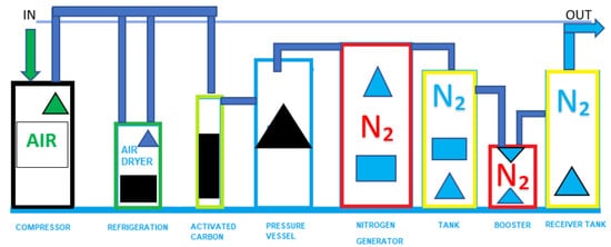
9]. Air is the invisible gaseous substance surrounding the Earth, a mixture mainly of oxygen and nitrogen. Since air exists everywhere in the world and it consists of 78% nitrogen, there is an opportunity to utilize nitrogen in electrical power generation as shown in
Figure 1. It is necessary to invest in pollution treatment technologies which are mandatory for environmental protection as well [
10,
11]. Plus, energy storage is another factor in conserving energy as this method will store electrical power in batteries before it is transferred to consumers. Nevertheless, energy storage systems face many challenges such as charging, discharging, safety, size, cost, reliability, and overall management. What is more important to be concerned about than those challenges is the cost of production of batteries. However, there is a chance in the future that production costs would be lower as the method of battery production is improved [
12,
13,
14,
15,
16,
17,
18,
19,
20,
21,
22,
23].
Figure 1. Nitrogen generator flow diagram.
Technology Description Basic Process is a theory which describes the thermodynamic cycle for the steam turbine which is known as the Rankine cycle [
24,
25,
26]. This cycle is the basis for conventional power generating stations and consists of a heat source (boiler) that converts water to high pressure steam. In the steam cycle, water is first pumped to elevated pressure, which is a medium to high pressure depending on the size of the unit and the temperature to which the steam is eventually heated. It is then heated to the boiling temperature point corresponding to the pressure, boiled (heated from liquid to vapor), and then most frequently superheated (heated to a temperature above that of boiling). The pressurized steam is expanded to lower pressure in a turbine, then transferred either to a condenser at vacuum conditions, or into an intermediate temperature steam distribution system that delivers the steam to the industrial or commercial application. The condensate from the condenser or from the industrial steam utilization system is returned to the feedwater pump for continuation of the cycle [
27]. Steam turbines have been used to generate electrical power for decades and they have been greatly improved to perform more efficiently in a wider range of functions and can be used diversely to create energy sustainability [
28]. Steam turbines are one of the most versatile and oldest prime mover technologies still in general production used to drive a generator or mechanical machinery. The first steam turbine used for power generation was invented in 1884. Following this initial introduction, steam turbines rapidly replaced reciprocating steam engines due to their higher efficiencies and lower costs. Most of the electricity produced in the United States today is generated by conventional steam turbine power plants. The capacity of steam turbines can range from 50 kW to several hundred MWs for large utility power plants. Steam turbines are widely used for combined heat and power (CHP) applications in the United States and Europe [
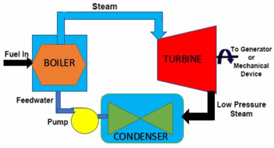
27]. Steam turbines are well suited to medium- and large-scale industrial and institutional applications, where inexpensive fuels, such as coal, biomass, solid wastes and byproducts (e.g., wood chips), refinery residual oil, and refinery off gases are available. An injection turbine is the primary type of turbine used for central power generation; the injection turbine is shown schematically in
Figure 2. These power-only utility turbines feed directly to condensers that maintain vacuum conditions at the discharge of the turbine. An array of tubes, cooled by water from a river, lake, or cooling tower, condenses the steam into (liquid) water [
29]. The vacuum conditions in the condenser are caused by the near ambient cooling water resulting in condensation of the exhaust steam in the condenser. As a small amount of air is known to leak into the system when it is below atmospheric pressure, a relatively small compressor or steam air ejector may be used to remove non-condensable gases from the condenser. Non-condensable gases include both air and a small amount of the corrosion byproduct of the water-iron reaction, hydrogen. The injection turbine process results in maximum power and electrical generation efficiency from the steam supply and boiler fuel. The power output of injection turbines is sensitive to ambient conditions [
27,
30,
31,
32,
33]. Unlike the finite amount of fossil fuels, nitrogen is in no short supply and makes up 78% of the air that surrounds us [
34]. Nitrogen is considered one of the most important gases in petrochemical industries, which commonly use it as an inert gas in pipes and polyethylene production and in utilities of refineries to clean the primary oven from combustions results. There is more than one method to produce nitrogen gas pressure swing adsorption, membrane technology and cryogenic system and these various methods differ in purity of product, efficiency, environmental impact, and cost [
35]. Moreover, gaseous nitrogen is used in a number of other important functions such as to detect a gas pipe leak [
36,
37,
38,
39] and to pressurize the turbine of an injection steam turbine [
40,
41]. Moreover, liquid nitrogen is combined with injection steam turbines to drive engines and it can save water for the cooling system by up to 30% [
42]. Additionally, both gaseous nitrogen and liquid nitrogen are used to generate electrical power for small engines, especially liquid nitrogen which is suitable for off-grid areas such as islands and rural areas [
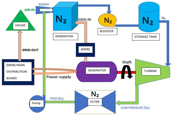
43]. In 1982, David G. Elliott used gaseous nitrogen to pressurize the turbines and the result was compared to hydro pressure, which was published in “Theory and Tests of Two-Phase Turbines” and this became an integral part in NASA’s work NASA Task Order RD 152, Amendment 266. A key component of this study is the process of generating the Nitrogen Turbine Engine (NTE) as shown in
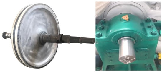
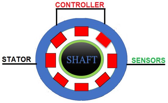
Figure 3, which requires magnetic bearing installations. A magnetic bearing is an oil-free bearing system that uses electromagnetic forces to maintain the relative position of a rotating assembly (rotor) to a stationary component stator [
44] as shown in
Figure 4 and
Figure 5. An advanced electronic control system adjusts these electromagnetic forces in response to forces generated from machine operation [
45]. A prototype must be assembled to run the work process and include such aspects as a design to enable the flow of the nitrogen gas direction. Thus, a highly precise program like Computational Fluid Dynamics (CFD) is required. Computational Fluid Dynamics (CFD) is simulation software to solve complex flow equations with accurate numerical methods, powerful turbulence modeling CAD models [
46], and intensive computing power [
47].
Figure 2. Schematic of injection steam turbine.
Figure 3. Schematic conceptual model of the nitrogen turbine engine system (NTES).
Figure 4. A turbine and shafts.
Figure 5. Schematic of the cross-section of the magnetic bearing system.
2. Theoretical Implications
This study offers theoretical contributions to several research streams. The first steam turbine used for power generation was invented in 1884 [
27]. It has been 137 years that we have now depended on the Rankine cycle theory [
25] which describes the thermodynamic cycle [
26]. However, this theory has a major drawback in that it causes pollution. The Rankine cycle needs to burn natural resources such as fossil fuels, causing high temperature reactions with water in order to create high pressure steam. After the steam is generated, it is used to drive the turbine and the turbine will then drive the steam turbine engine. The steam turbine engine is assembled with the generator to produce mechanical power which is transformed to electrical power. Then, electrical power is transferred to the transformer system and it becomes electrical power which is the most common form of energy used by people today. Some progress has been made in the clean energy field, such as solar cells which depend mainly on solar power, wind turbines which use wind power, and hydropower which uses water as a source to generate power; yet, these three technologies have limitations in power generation as they cannot operate for 24 h continuously. Moreover, they have both direct and indirect impacts on the environment. As mentioned previously, injection steam turbines were invented to resolve those drawbacks. The injection steam turbines save water used to heat up fossil fuels in order to generate high pressure steam, which is used to drive the turbines. The system is designed to push the remaining low-pressure steam into the condenser and the steam can be reused in a condenser unit by pump. This will save energy on the steam consumption rate of up to 20% [
30,
31,
32,
33]. Therefore, the authors see opportunities to develop conventional electrical power generation to be a better technology. In the authors’ point of view, the conventional injection steam turbines should be improved by being combined with a nitrogen generator. The nitrogen generator generates gaseous nitrogen from the air that exists in nature. The nitrogen generator separates nitrogen from air, then 78% of gaseous nitrogen is used to drive the turbine and the injection steam turbine instead of using steam. This applied technology is based on the original technology, but it is advanced by using the cooling power of gaseous nitrogen to drive the turbine in the input process instead of using the heat power of steam as it has been used for decades. Additionally, the original theory is applied by the second law of thermodynamics which describes the refrigerating cycle and heat pump cycle. It explains how the system suctions air from outside to transform heat from low temperature to high temperature; this is called the refrigerating cycle and heat pump cycle. Both the refrigerating cycle and heat pump cycle are similar to a reversed Rankine cycle. However, the primary difference among these three theories is flow direction. The refrigerating cycle and heat pump cycle need a compression stroke. The compression stroke is divided into two systems which are the compressor vapor compression refrigeration cycle and the absorption refrigeration cycle. The compression stroke changes steam pressure caused by density of the changing temperature [
39]. Moreover, the engine needs to be redesigned, and this will be a revolution of electrical power generation which is similar to vertical rocket landing and electric vehicles. Vertical rocket landing and electric vehicles preserve the environment and limit the overuse of natural resources. Numerous studies have been conducted to find possibilities of applying gaseous nitrogen to generate electrical power. It was found that an American inventor succeeded in patenting his work in 2015 in the United States by using liquid nitrogen to drive the turbine and injection steam turbine of thermal power plants. By applying liquid nitrogen, the water in the cooling system saved energy by up to 30% [
42]. Furthermore, inventors patented their European Patent in Brazil in 2007 by using liquid nitrogen to pressurize power generation systems to generate and merchandise electrical power in off grid areas [
74]. These two patents used and applied liquid nitrogen. In 1982, David G. Elliott used gaseous nitrogen to pressurize the turbines and the result was compared to hydro pressure, which was published in “Theory and Tests of Two-Phase Turbines”. This became a part in NASA’s work NASA Task Order RD 152, Amendment 266. Hence, the authors have carefully considered that the potential of gaseous nitrogen to revolutionize energy production is extremely high as it possesses most of the similar properties to steam, but it has more advantages. First, gaseous gas is generated more easily than steam. Second, the system that generates gaseous nitrogen does not require a complicated process of installation and it can be installed and moved easily. Third, it does not need a burning process, so it does not cause pollution. It is also crucial to apply magnetic bearings to the centrifugal axle shaft system and turbines as this will not cause pollutants. Magnetic bearings do not require lubrication nor do they touch the centrifugal axle shaft (zero touch) [
66,
75]. A firm in Japan and the United States suggested that the installation of magnetic bearings to compressor technology of centrifugal chillers can save cost up to 42.3–50%/year [
76,
77,
78]. Reviews of technologies that use magnetic bearings with a compressor motor to avoid the touch between the axis and the other metal surfaces were conducted. The energy consumption rate in the system was measured and it was found to be practical when adopted in industries. In addition to magnetic bearings, artificial intelligence (AI) and CFD programs should be applied to the system as well [
69,
79,
80,
81]. They are used with this technology to analyze and control nitrogen gas flow in the machine to provide a more precise evaluation and make minor adjustments resulting in greater efficiency. They also support the hypothesis of the original theory that the turbine was designed to be high heat proof and corrosion proof, both of which can be caused by steam. Nevertheless, the modified technology uses 40 °C gaseous nitrogen and there are possibilities to design turbine and axle shafts that can withstand 40 °C temperature and they can be altered to be lightweight to fit nitrogen pressure. Through modifications and these fairly simple components, a truly green technology can be attainable.
3. Results and Discussion
3.1. Comparison of Effectiveness and Properties of Nitrogen and Steam
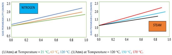
A review of the theoretical framework found that experiments to measure nitrogen/water two-phase relative permeabilities were conducted at a room temperature of approximately 21 °C. The gas distribution factors of nitrogen and steam flow through porous media were measured at different temperatures up to approximately 170 °C. It was also suggested that steam needs to be burned from fossil fuels before it can generate desired temperature levels, which means it costs fuel [
27]. In this experiment, the steam temperatures tested were 120, 150, and 170 °C, while the nitrogen temperature was kept at 21 °C. Then, the nitrogen temperature was increased to 63 and 120 °C [
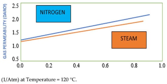
82]. It was obvious that both the nitrogen and steam gas distribution factors increased with temperature. The steam gas distribution factor was significantly less than that of nitrogen at the same temperature of 120 °C, as is shown in
Figure 7 and
Figure 8 [
83].
Figure 7. Comparison of the nitrogen and steam gas distribution effects at different temperatures.
Figure 8. Comparison of the nitrogen and steam gas distribution factor test.
The statement mentioned above was coherent with the data shown in
Table 4 which compared the result of the nitrogen injection turbine and the steam turbine. After that, different pressure and temperature adjustments were made to examine the density of nitrogen and steam. It was found that after the pressure was increased to 1 bar, the nitrogen temperature was stable at 40 °C and the nitrogen density was 1.081 (kg/m
3), while steam temperature was 99.63 °C and the steam density was 0.590 (kg/m
3). Then, when the pressure was increased to 10 bar, it revealed that the nitrogen temperature was still stable at 40 °C and the nitrogen density was 10.600 (kg/m
3), while steam temperature was 179.88 °C and the steam density was 5.147 (kg/m
3). Lastly, when the pressure was increased to 30 (bar), it can be seen that the nitrogen temperature remained at 40 °C and the nitrogen density was 32.300 (kg/m
3), while steam temperature was 233.84 °C and the steam density was 15.009 (kg/m
3). It was clear that the higher the pressure, the greater the gas distribution of nitrogen generated [
84]. Similar results were obtained which stated that when compressing more pressure into the turbine, higher density was generated. It can be concluded that when temperature and pressure increased, the distribution levels of nitrogen became significantly higher as shown in
Table 4. There is a possibility of using nitrogen to generate electrical power instead of steam, or nitrogen could be combined with steam to drive the engine of the injection steam generating electrical power as well [
42,
85].
3.2. Efficiency Comparison of N2 Generator and with injection Steam Turbine Engine
After the nitrogen system and injection steam turbine were compared, it was found that with 5000 (Nm
3/h) at a temperature of 40 °C and pressure of 34.30 bar, the nitrogen generator can produce a gas flow rate of 6261.10 (kg/h) [
86], which was not enough to be used to drive the propeller which generates mechanical power that drives an electricity generator in the systems with conventional injection steam turbine [
87,
88,
89]. Then, a 6000 kW/h injection steam turbine with a rotation speed of 8000 (rpm) was studied and it was found that steam pressure of 34.30 bar was required [
90] After that, the injection steam turbine was compared with a nitrogen generator and it was obvious that the nitrogen booster combined with a nitrogen generator generated significantly higher pressure of up to 300 bar. Moreover, the engine of the injection steam turbine was designed to be used with a steam temperature of 435 °C. In contrast, the nitrogen generator was designed to be used with a lower temperature of 40 °C. It is crucial to analyze the consumption rate of steam used in the conventional injection steam turbine. The consumption rate of the conventional injection steam turbine was 6.36 (kg/s) which consumed more steam energy than the 5000 (Nm
3/h) nitrogen generator which consumed steam energy at a rate of only 1.73 (kg/s). This point led to the development of a new engine [
73] called the Nitrogen Turbine Engine (NTE). Therefore, one c injection steam turbine is required to be used with four nitrogen generators in order to generate enough nitrogen gas driving 6000 (kW/h) conventional injection steam turbines to reach the most efficient and effective electrical power generation [
86] as shown in
Table 5. The break-even point should also be considered to save excessive energy used to generate electrical power. It is also crucial to apply magnetic bearings to the centrifugal axle shaft system and turbines as this will not cause pollutants. Magnetic bearings do not require lubrication, nor do they touch the centrifugal axle shaft (zero touch) [
66,
75]. A firm in Japan and the United States suggested that the installation of magnetic bearings to compressor technology of centrifugal chillers can save costs up to 42.3–50%/year [
76,
77,
78]. Reviews of technologies that use a magnetic bearing with a compressor motor to avoid the touch between the axis and the other metal surfaces were conducted. The energy consumption rate in the system was measured and it was found to be practical when adopted in industries. In addition to magnetic bearings, artificial intelligence (AI) and CFD programs should be applied to the system as well [
69,
79,
80,
81]. They are used with this technology to analyze and control nitrogen gas flow in the turbine to provide a more precise evaluation and change materials resulting in a more efficient technology. They also support the hypothesis of the original theory that the turbine was designed to be high heat proof and corrosion proof, both of which can be caused by steam. Nevertheless, the modified technology uses 40 °C gaseous nitrogen and there are possibilities to design turbine and axle shafts that can withstand 40 °C temperature and they can be altered to be lightweight to fit nitrogen pressure as shown in
Table 6 [
58].
Table 5. Comparison of nitrogen gas and steam gas.
| Parameters |
Temperature
(°C) |
Pressure
(bar) |
Density
(kg/m3) |
| Nitrogen |
40 |
1.0 |
1.081 |
| |
40 |
10 |
10.600 |
| |
40 |
30 |
32.300 |
| Steam |
99.63 |
1.0 |
0.590 |
| |
179.88 |
10 |
5.147 |
| |
233.84 |
30 |
15.009 |
Table 6. Comparison of nitrogen generator (N₂) product model: PN-capacity-purity and injection steam turbine (steam) product model: (BN6-3.43/0.4).
| No. |
Parameters |
Injection Steam Turbine |
Nitrogen Generator Size 5000 (Nm3/h) |
| 1 |
Electrical generator output (kW/h) |
6000 |
- |
| 2 |
Speed (rpm) |
8000 |
- |
| 3 |
Pressure into the system (bar) |
34.30 |
34.30–300 |
| 4 |
Temperature inside the system (°C) |
435 |
40 |
| 5 |
Gas energy consumption rate (kg/s) |
6.36 |
1.73 |
| 6 |
Balanced gas production ratio per one unit and in this case the equation has not yet been modified (Set) |
1 |
4 |
This entry is adapted from the peer-reviewed paper 10.3390/inventions6040062