Abstract
The results obtained from the design and analysis of a photovoltaic-hydrogen-PEM fuel cell (PVHPEMFC) hybrid system for Najaf City in Iraq has been presented. The hybrid system consists of photovoltaic arrays coupled with an electrolyzer to produce hydrogen, a PEM fuel cell that converts chemical energy (H2) to electricity, hydrogen storage, a battery storage system, and the load. In this kind of system, all components can be connected electrically in parallel. The voltage of the PV arrays and fuel cell must be high enough to charge the battery, and the voltage of the electrolyzer must be low enough for the battery to power it during periods of low insolation. The designed system model is based on the electrical component models and variable solar radiation data depending on the location.
- Stand-alone power systems
- PV-Hydrogen
- Solar Energy
- PEM fuel cell
- Energy conversion
INTRODUCTION
Fossil fuels, which meet most of the world's energy demand today, are being depleted rapidly. Also, their combustion products are causing global problems, such as the greenhouse effect, ozone layer depletion, acid rains and pollution, which are posing great danger for our environment, and eventually, for the total life on our planet. Many engineers and scientists [1][2][3][4][5][6][7][8][9][10][11][12][13][14][15][16][17][18] reach a decision that the solution to all of these global problems would be to replace the existing fossil fuel systems with the clean renewable energy systems.
Renewable energy sources, such as solar energy, are inherently intermittent. The capacity factor, defined as a ratio between average power over a period of time and maximum or nominal power, is about 20% for solar installations. A PEM fuel cell may be used to store the excess energy when the solar energy is available, by converting electricity to hydrogen, and then generate electricity from hydrogen using PEM fuel cell when this renewable source is not available.
Hydrogen has some unique properties that make it an ideal energy carrier, namely [1], [16]:
- It can be produced from and converted into electricity at relatively high efficiencies.
- Raw material for hydrogen production is water, which is available in abundance. Hydrogen is a completely renewable fuel, because the product of hydrogen utilization through electrochemical conversion is pure water.
- It can be stored in gaseous form (convenient for large-scale storage), in liquid form (convenient for air and space transportation), or in the form of metal or chemical hydrides (convenient for surface vehicles and other relatively small-scale storage requirements).
- It can be transported over large distances through pipelines or via tankers (in some cases more efficiently and economically than electricity).
- It can be converted into other forms of energy in more ways and more efficiently than any other fuel.
- Hydrogen as an energy carrier is environmentally compatible, its storage, transportation, and end use do not produce any pollutants, greenhouse gases, or any other harmful effects on the environment. Hydrogen itself is not toxic.
- Hydrogen is a relatively safe fuel if handled properly.
Water electrolysis is a mature technology and was developed for hydrogen production capacities ranging from a few cm3/min to thousands m3/hr. It is relatively efficient, but because it needs high-quality energy (electricity), hydrogen produced by water electrolysis is expensive. Full benefits of hydrogen will be realized only in conjunction with renewable energy sources. Both hydrogen and electricity complement the renewable energy sources and allow their indirect utilization in almost every imaginable application. Such a system is in complete balance with the environment.
Electrolyser's power input vs fuel cell power output depends on the capacity factors of both source and load, and on the efficiencies of both electrolyser and fuel cell as well as the efficiency of hydrogen storage. If the load requires constant power then the electrolyser connected to a solar power source may have power input up to 10 times higher than the fuel cell power output. The size of hydrogen storage depends on the dynamics of hydrogen production and consumption. However, if the storage must account for not only daily but also seasonal variations in renewable source availability, then required hydrogen storage may be quite large.
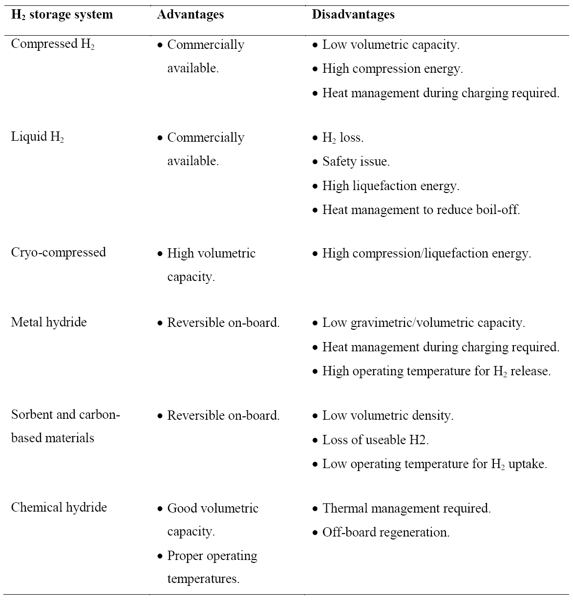
Hydrogen as an energy carrier must be stored to overcome daily and seasonal discrepancies between energy source availability and demand. Hydrogen can be stored physically as either a gas or a liquid. Storage of hydrogen as a gas typically requires high-pressure tanks (350–700 bar [5,000–10,000 psi] tank pressure). Storage of hydrogen as a liquid requires cryogenic temperatures because the boiling point of hydrogen at one atmosphere pressure is (−252.8°C). Hydrogen can also be stored on the surfaces of solids (by adsorption) or within solids (by absorption). Metal hydride tank is a container loading with hydrogen storage alloy powder, heat exchange parts, and gas transport components. The container body materials are generally aluminium alloy or stainless steel. Hydrogen is stored in the form of so-called “metal hydride”. Most metals or alloys can react with hydrogen to form new compounds, which are named as metal hydrides. The formation of metal hydride is an exothermic process associated with heat releasing. With sufficient heat supply, hydrogen can be released from the as-formed metal hydride. Some metal hydrides have the potential for reversible on-board hydrogen storage and release hydrogen at the relatively low temperatures and pressures required for fuel cells. The advantages and disadvantages for each approach are summarized in Table 1.
Table 1. Advantages and disadvantages of different hydrogen storage approaches.
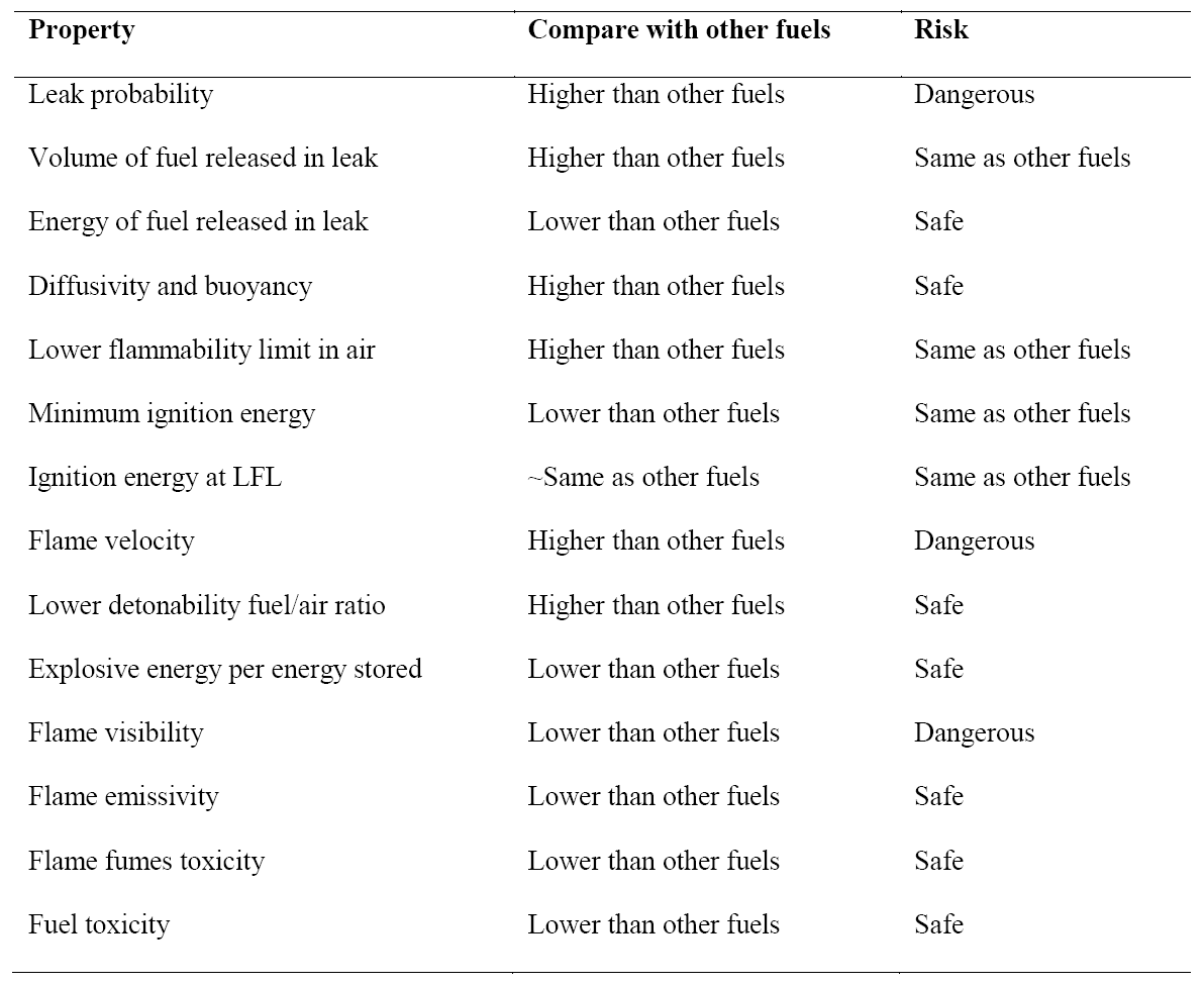
Like any other fuel or energy carrier, hydrogen poses risks if not properly handled or controlled. The risk of hydrogen, therefore, must be considered relative to the common fuels such as gasoline, propane, or natural gas. The specific physical characteristics of hydrogen are quite different from those common fuels. Some of these properties make hydrogen potentially less hazardous, whereas other hydrogen characteristics could theoretically make it more dangerous in certain situations. Table 2 compares hydrogen properties with other fuels and ranks their effect on safety [3], [7], [18].
Table 2. Summary of hydrogen safety related properties compared with other fuels.
SYSTEM DESIGN
In a photovoltaic-hydrogen-PEM fuel cell (PVHPEMFC) energy system, electricity is produced by a PV array to meet the requirements of a load. When there is enough solar radiation available, the external load can be powered totally by the PV electricity. During periods of low insolation, auxiliary electricity is required. A hydrogen energy system, formed by an electrolyzer, a hydrogen storage system, and a PEM fuel cell that works as an auxiliary generator, has been studied in several projects as a complementary system showing good performance [12], [14], [15], [17] A schematic diagram of the PVHPEMFC energy system is displayed in Figure 1.
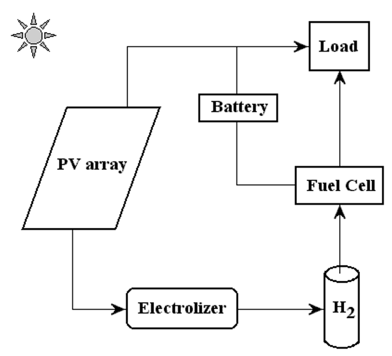
Figure. 1. A schematic picture of the PVHFC hybrid energy system.
In this system, excess electricity generated in the photovoltaic array is sent to an electrolyzer to produce H2, which is stored for a period of time to be converted, when required, into electricity using the PEM fuel cell. The PEM fuel cell can be considered as a back-up generator to meet the load requirement and charge the battery when the electricity from the photovoltaic arrays is low.
In this work, the simulation of a PVHPEMFC energy system to power a 1000 W constant load has been reported. Simulation was done for Najaf City in Iraq (32o 02/ N).
The average radiation on a horizontal surface for Najaf City was obtained at the Research Center of Solar Energy (Figure 2). The PV array consists of several sub-arrays; the number of sub-arrays varied depending on the meteorological data. Each sub-array consists of 18 modules, wired in nine series pairs for 24 V DC operation. In this system, the PV array, the constant load, and the electrolyzer are connected directly. During operating, the PEM fuel cell is also connected directly to the load. The idea of this kind of system is to operate the load with PV electricity during high insolation periods. In the seasonal storage concept, the electrolyzer produces H2 in summer, which is stored during this season. During the months of low insolation (winter) the PEM fuel cell converts H2 back to electricity. The battery storage is used for short-term storage of electricity.
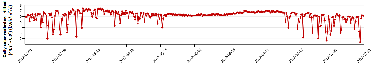
Figure 2. Radiation on a horizontal surface for Najaf city [kW.h/m2/d]
SYSTEM CONTROL
The system control is designed to optimize the input and output currents for the different components of the overall system during a period of one year. The flow chart of the PVHPEMFC system is shown in Figure 3.
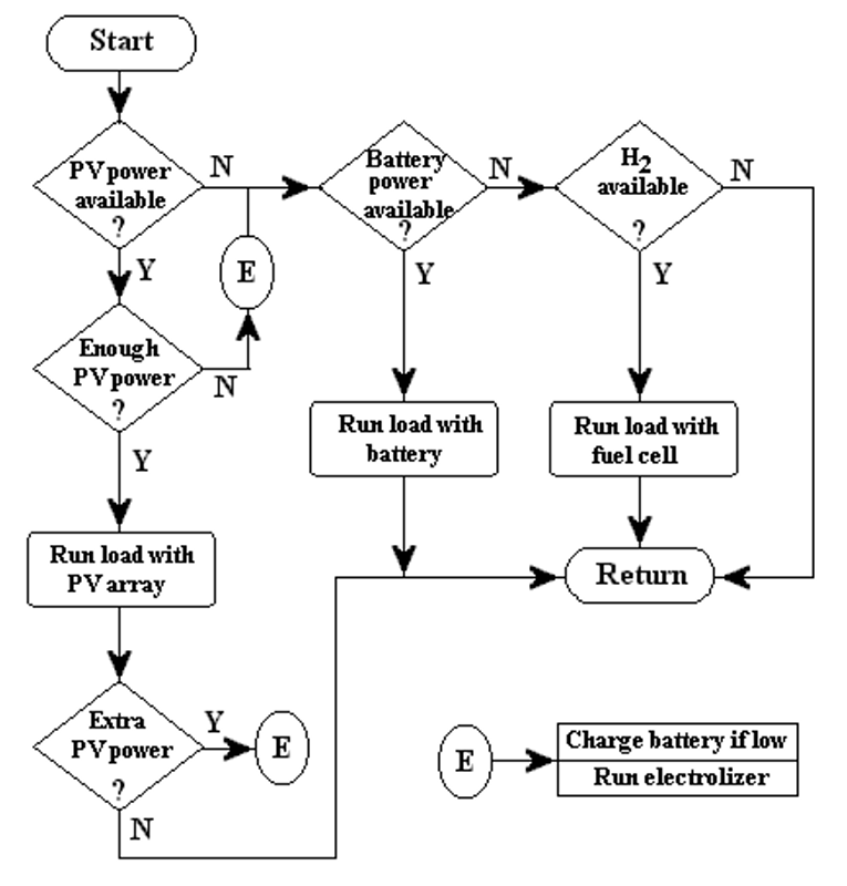
Figure 3. The flow chart of the PVHFC system.
Three different cases are considered in our system model, based on the insolation data. These cases are:
- The current from the PV array is high enough to power the load, and there is no excess current to be used in other components of the system.
- There is enough PV current to operate the electrolyzer but not enough current to power the load - the minimum current requirement for the electrolyzer to operate is 10 A. Currents less than 10 A are used to charge the battery. Excess current from the PV array is also sent to the electrolyzer. Only if the depth of discharge (DOD) limit of the battery is reached, is excess PV current sent to this component.
- There is no PV current, so the electricity must be obtained from the auxiliary system.
The idea of this kind of system is to use the battery in periods of high insolation (short term storage) and the fuel cell during the winter (long term storage) or when the discharge limit of the battery is reached. In case (2) mentioned above; if the electrolyzer does not start its operation in the correct time and the battery DOD raises over the precaution limit, the PV array is disconnected to prevent damages. The three cases are illustrated in Figure 3 as the flow chart of the system.
SIMULATION DETAILS
Figure 4 shows the variation of monthly average daily solar radiation with tilt angle of the plane of the PV modules for Najaf City. The simulation program input data is the monthly average daily solar radiation for optimum tilt angle (Figure 5). The system program calculates the total number of sub-arrays from the irradiation data for optimum tilt angle. Once this information is obtained, the simulation starts, based on the above mentioned system control.
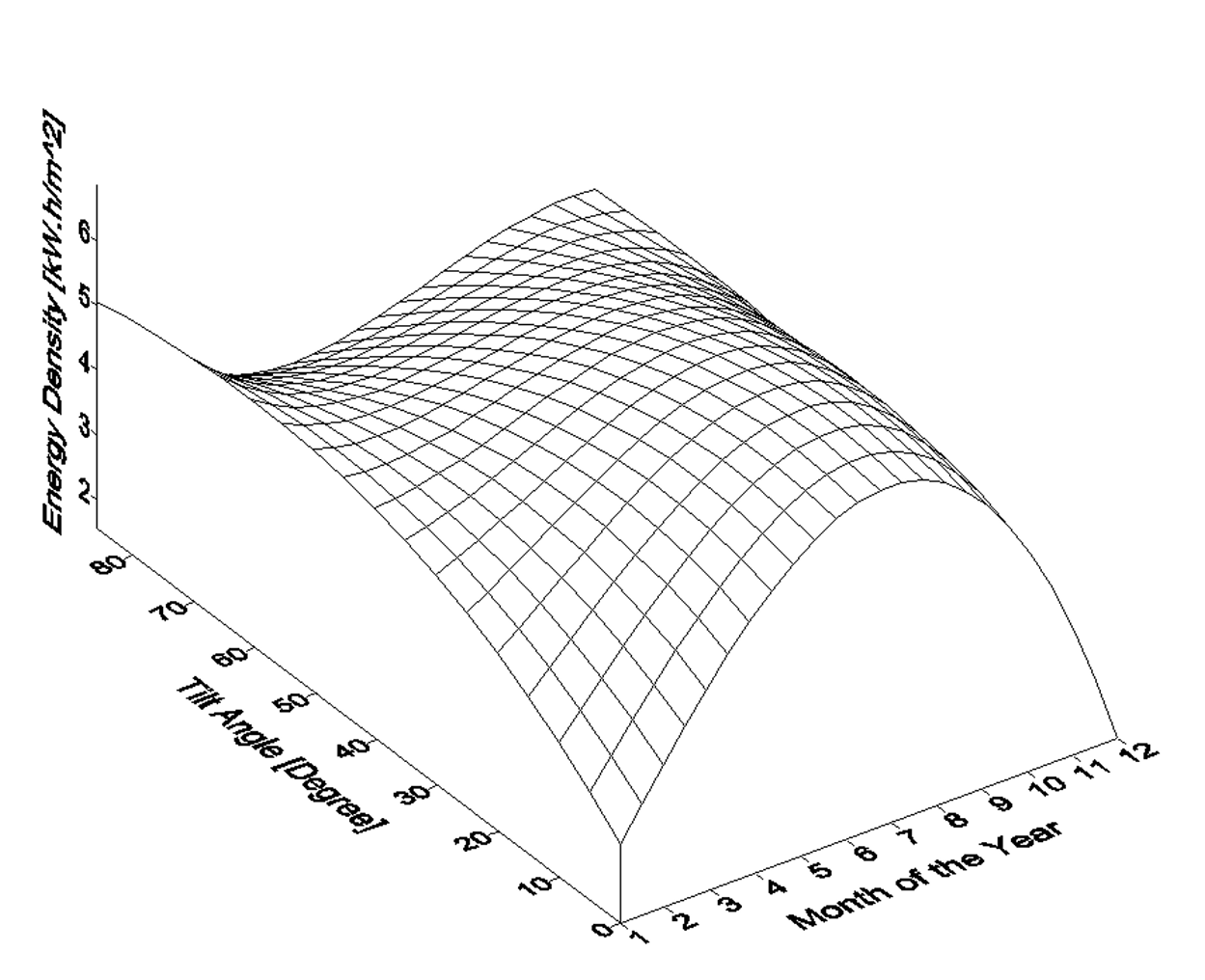
Figure 4. Variation of monthly average daily solar radiation with tilt angle of the plane of the PV modules for Najaf City.
RESULTS
The proposed system showed good performance in meeting the power supplies during the year in the Najaf City. The objective of using hydrogen energy during winter was fulfilled. The PEM fuel cell operates only in December during the year.
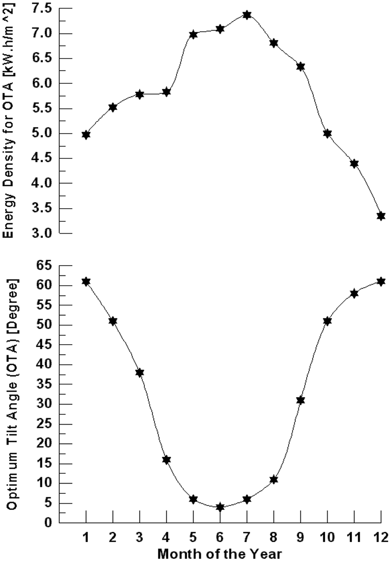
Figure 5. Monthly average daily solar radiation for optimum tilt angle of the plane of the PV modules for Najaf City.
Figure 6 shows the monthly energy produced by the PV array (for optimum tilt angle) and the energy consumed by the electrolyzer for Najaf City. It is shown that in December, the PV electricity is lowers then the load requirements and auxiliary energy is necessary. During this period the fuel cell operates. PV electricity is high enough to run the load in the months of high insolation. Only during the December it is necessary to use the hydrogen energy. When insolation is low, current produced by the PV array is sent to the battery. When the current is 10 amp or more, it is supplied to the electrolyzer. Only when the PV current reaches the minimum value to run the load, is it used for this purpose. The energy excess is always sent to the electrolyzer.
For Najaf City, it is necessary to use the PEM fuel cell in one month (December) if the optimum tilt angle of the plane of the PV modules is used. The PEM fuel cell energy needed for December is 20.96 kW. For the horizontal plane (zero angles) of the PV models, the fuel cell operates only in January, November and December during the year (Figure 7). The fuel cell energy needed for these months are 29.34, 13.41, and 45.11 kW respectively.
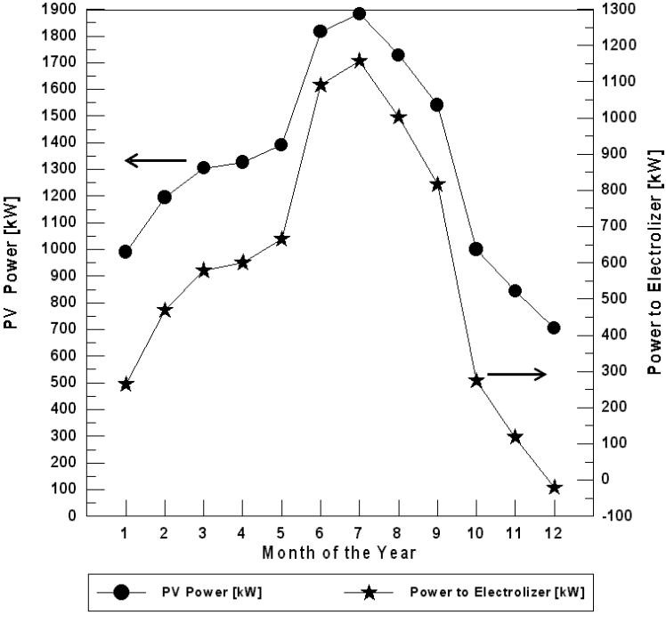
Figure 6. The monthly energy balance for Najaf City (for optimum tilt angle of the plane of the PV modules).
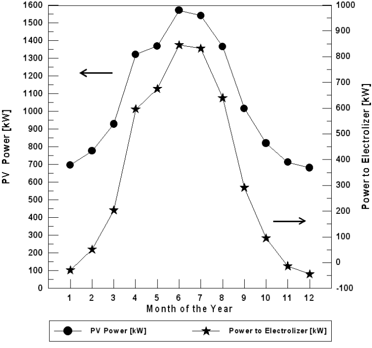
Figure 7. The monthly energy balance for Najaf City (for horizontal plane of the PV modules).
CONCLUSION
The PVHFC hybrid system consists of photovoltaic arrays coupled with an electrolyzer to produce hydrogen, a fuel cell that converts chemical energy H2 to electricity, hydrogen storage, a battery storage system, and the load. In this kind of system, all components can be connected electrically in parallel. The voltage of the PV arrays and the fuel cell must be high enough to charge the battery, and the voltage of the electrolyzer must be low enough for the battery to power it during periods of low insolation. The simulation is based on the electrical component models and variable insolation data depending on the location. The PVHFC system shows good performance to meet the constant load using energy produced for the photovoltaic array (for optimum tilt angle) or the hydrogen system. The objective of the system that the fuel cell operates only during the winter is reached. The number of PV sub-arrays can be varied to see the increase of hydrogen energy demand during the months of low insolation.
Acknowledgements
The author would like to thank the Fuel Cell Research Center (www.ieefoundation.org), The International Energy and Environment Foundation (IEEF), for valuable technical support and providing the experimental data.
References
- Maher A.R. Sadiq Al-Baghdadi. PEM Fuel Cells: Fundamentals, Modeling, and Applications. International Energy and Environment Foundation (IEEF), Najaf, Iraq. 2013. ISBN-13: 9781481978231
- Oystein Ulleberg. The importance of control strategies in PV–hydrogen systems. Solar Energy 2004; 76(1-3): 323-329
- Maher A.R. Sadiq Al-Baghdadi. Three-dimensional computational fluid dynamics model of a tubular-shaped PEM fuel cell. Renewable Energy Journal 2008; 33(6) pp.1334-1345
- M.P. Rzayeva, O.M. Salamov and M.K. Kerimov. Modeling to get hydrogen and oxygen by solar water electrolysis. Int J Hydrogen Energy 2001; 26(3):195-201.
- M. T. Iqbal. Simulation of a small wind fuel cell hybrid energy system. Renewable Energy 2003; 28(4): 511-522
- M. Inoue, N. Hasegawa, R. Uehara, N. Gokon, H. Kaneko and Y. Tamaura. Solar hydrogen generation with H2O/ZnO/MnFe2O4 system. Solar Energy 2004; 76(1-3): 309-315
- Maher A.R. Sadiq Al-Baghdadi. Performance comparison between airflow-channel and ambient air-breathing PEM fuel cells using three-dimensional computational fluid dynamics models. Renewable Energy Journal 2009; 34(7) pp.1812-1824
- M. T. Iqbal. Modeling and control of a wind fuel cell hybrid energy system. Renewable Energy 2003; 28(2): 223-237
- Maher A.R. Sadiq Al-Baghdadi. Performance comparison between planar and tubular-shaped ambient air-breathing PEM fuel cells using three-dimensional computational fluid dynamics models. Journal of Renewable and Sustainable Energy 2009; 1(2) pp.023105-1 - 023105-15
- J. P. Vanhanen, P. S. Kauranen and P. D. Lund. Operation experiences of a phosphoric acid fuel cell in a solar hydrogen energy system. Int J Hydrogen Energy 1997; 22(7):707-713
- Maher A.R. Sadiq Al-Baghdadi. A CFD analysis of transport phenomena and electrochemical reactions in a tubular-shaped ambient air-breathing PEM micro fuel cell. The Hong Kong Institution of Engineers Transactions (HKIE Transactions) 2010; 17(2) pp.1-8
- S. Galli and M. Stefanoni. Development of a solar-hydrogen cycle in Italy. Int J Hydrogen Energy 1997; 22(5):453-458
- Maher A.R. Sadiq Al-Baghdadi. Performance, Water and Thermal Management, and Mechanical Related Failure in PEM Fuel Cells - A CFD Study. Journal of Mechatronics, Electrical Power, and Vehicular Technology 2016; 7(1) pp. 7-20
- L. A. Torres, F. J. Rodriguez and P. J. Sebastian. Simulation of a solar-hydrogen-fuel cell system: results for different locations in Mexico. Int J Hydrogen Energy 1998; 23(11):1005-1009
- Phoebus-Julich, An autonomous energy supply system comprising photovoltaics, electrolytic hydrogen, fuel cell. Int J Hydrogen Energy 1998; 23(4):295-301
- Maher A.R. Sadiq Al-Baghdadi. PEM Fuel Cell Engines: Principles, Design, Modelling, and Analysis. International Energy and Environment Foundation (IEEF), Najaf, Iraq. 2018, (478 pages). ISBN-13: 9781983474996.
- A. Mills and S. Al-Hallaj. Simulation of hydrogen-based hybrid systems using Hybrid2. Int J Hydrogen Energy 2004; 29(10):991-999
- Maher A.R. Sadiq Al-Baghdadi. PEM Fuel Cells - from Single Cell to Stack. International Energy and Environment Foundation (IEEF), Najaf, Iraq. 2015, (382 pages). ISBN-13: 9781505885644.