Shear often attributed as being the main source of cell deformation/damage in devices like prosthetic heart valves and artificial organs. Less well understood and studied are extensional stresses which are often found in such devices, in bioreactors, and in normal blood circulation. Several microfluidic channels utilizing hyperbolic, abrupt, or tapered constrictions and cross-flow geometries, have been used to isolate the effects of extensional flow. Under such flow cell deformations, erythrocytes, leukocytes, and a variety of other cell types have been examined. Results suggest that extensional stresses cause larger deformation than shear stresses of the same magnitude. This has further implications in assessing cell injury from mechanical forces in artificial organs and bioreactors. The cells’ greater sensitivity to extensional stress has found utility in mechanophenotyping devices, which have been successfully used to identify pathologies that affect cell deformability. Further application outside of biology includes disrupting cells for increased food product stability and harvesting macromolecules for biofuel.
- elongational stress
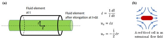
- elongational flow
- cell mechanics
1. Introduction
2. Experimental Methods for Extensional Stresses on Cells
| Method | Pros | Cons | Key Results |
|---|---|---|---|
| Hyperbolic Microfluidic Devices |
|
|
|
| Abrupt/Tapered Constriction Microfluidic Devices |
|
|
|
| Cross-Flow Microfluidic Devices |
|
|
|
| Optical Tweezers |
|
|
|
2.1. Microfluidic Systems Based on Flow through a Contraction
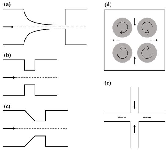
2.2. Taylor’s Four-Roll Mill
2.3. Cross-Flow Microfluidic Systems
2.4. Optical Tweezers
This entry is adapted from the peer-reviewed paper 10.3390/cells10092352
References
- Korenaga, R.; Ando, J.; Tsuboi, H.; Yang, W.D.; Sakuma, I.; Toyooka, T.; Kamiya, A. Laminar-Flow Stimulates Atp- and Shear Stress-Dependent Nitric-Oxide Production in Cultured Bovine Endothelial-Cells. Biochem. Biophys. Res. Commun. 1994, 198, 213–219.
- Kuchan, M.J.; Frangos, J.A. Role of Calcium and Calmodulin in Flow-Induced Nitric-Oxide Production in Endothelial-Cells. Am. J. Physiol. 1994, 266, C628–C636.
- Poelmann, R.E.; Groot, A.C.G.D.; Hierck, B.P. The development of the heart and microcirculation: Role of shear stress. Med. Biol. Eng. Comput. 2008, 46, 479–484.
- McIntosh, W.H.; Ozturk, M.; Down, L.A.; Papavassiliou, D.V.; O’Rear, E.A. Hemodynamics of the renal artery ostia with implications for their structural development and efficiency of flow. Biorheology 2015, 52, 257–268.
- Fraser, K.H.; Zhang, T.; Taskin, M.E.; Griffith, B.P.; Wu, Z.J. A quantitative comparison of mechanical blood damage parameters in rotary ventricular assist devices: Shear stress, exposure time and hemolysis index. J. Biomech. Eng. 2012, 134, 081002.
- Federici, A.B.; Budde, U.; Castaman, G.; Rand, J.H.; Tiede, A. Current diagnostic and therapeutic approaches to patients with acquired von Willebrand syndrome: A 2013 update. Semin. Thromb. Hemost. 2013, 39, 191–201.
- Heck, M.L.; Yen, A.; Snyder, T.A.; O’Rear, E.A.; Papavassiliou, D.V. Flow-Field Simulations and Hemolysis Estimates for the Food and Drug Administration Critical Path Initiative Centrifugal Blood Pump. Artif. Organs 2017, 41, E129–E140.
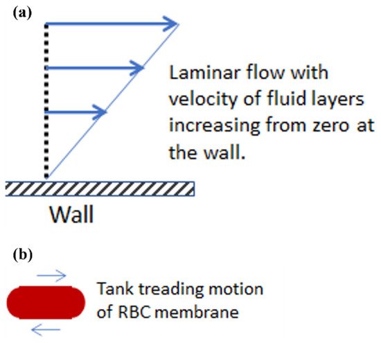
- Fischer, T.; Schmidschonbein, H. Tank Tread Motion of Red-Cell Membranes in Viscometric Flow-Behavior of Intracellular and Extracellular Markers (with Film). Blood Cells 1977, 3, 351–365.
- Ley, K.; Laudanna, C.; Cybulsky, M.I.; Nourshargh, S. Getting to the site of inflammation: The leukocyte adhesion cascade updated. Nat. Rev. Immunol. 2007, 7, 678–689.
- Yen, J.H.; Chen, S.F.; Chern, M.K.; Lu, P.C. The effects of extensional stress on red blood cell hemolysis. Biomed. Eng. Appl. Basis Commun. 2015, 27, 1550042.
- Balasundaram, B.; Harrison, S.T.L. Study of physical and biological factors involved in the disruption of E. coli by hydrodynamic cavitation. Biotechnol. Progr. 2006, 22, 907–913.
- Kubo, M.T.K.; Augusto, P.E.D.; Cristianini, M. Effect of high pressure homogenization (HPH) on the physical stability of tomato juice. Food Res. Int. 2013, 51, 170–179.
- Simmonds, M.J.; Atac, N.; Baskurt, O.K.; Meiselman, H.J.; Yalcin, O. Erythrocyte deformability responses to intermittent and continuous subhemolytic shear stress. Biorheology 2014, 51, 171–185.
- Ma, N.N.; Koelling, K.W.; Chalmers, J.J. Fabrication and use of a transient contractional flow device to quantify the sensitivity of mammalian and insect cells to hydrodynamic forces. Biotechnol. Bioeng. 2002, 80, 428–437.
- Buerck, J.P.; Burke, D.K.; Schmidtke, D.W.; Snyder, T.A.; Papavassiliou, D.; O’Rear, E.A. A Flow Induced Autoimmune Response and Accelerated Senescence of Red Blood Cells in Cardiovascular Devices. Sci. Rep. 2019, 9, 19443.
- Ober, T.J.; Haward, S.J.; Pipe, C.J.; Soulages, J.; McKinley, G.H. Microfluidic extensional rheometry using a hyperbolic contraction geometry. Rheol. Acta 2013, 52, 529–546.
- Faghih, M.M.; Sharp, M.K. Deformation of human red blood cells in extensional flow through a hyperbolic contraction. Biomech. Modeling Mechanobiol. 2020, 19, 251–261.
- Mancuso, J.E.; Ristenpart, W.D. Stretching of red blood cells at high strain rates. Phys. Rev. Fluids 2017, 2.
- Henon, Y.; Sheard, G.J.; Fouras, A. Erythrocyte deformation in a microfluidic cross-slot channel. Rsc Adv. 2014, 4, 36079–36088.
- Akbaridoust, F.; Philip, J.; Marusic, I. Assessment of a miniature four-roll mill and a cross-slot microchannel for high-strain-rate stagnation point flows. Meas. Sci. Technol. 2018, 29, 045302.
- Dao, M.; Lim, C.T.; Suresh, S. Mechanics of the human red blood cell deformed by optical tweezers. J. Mech. Phys. Solids 2003, 51, 2259–2280.
- Yaginuma, T.; Oliveira, M.S.N.; Lima, R.; Ishikawa, T.; Yamaguchi, T. Human red blood cell behavior under homogeneous extensional flow in a hyperbolic-shaped microchannel. Biomicrofluidics 2013, 7, 054110.
- Lee, S.S.; Yim, Y.; Ahn, K.H.; Lee, S.J. Extensional flow-based assessment of red blood cell deformability using hyperbolic converging microchannel. Biomed. Microdevices 2009, 11, 1021–1027.
- Faustino, V.; Rodrigues, R.O.; Pinho, D.; Costa, E.; Santos-Silva, A.; Miranda, V.; Amaral, J.S.; Lima, R. A Microfluidic Deformability Assessment of Pathological Red Blood Cells Flowing in a Hyperbolic Converging Microchannel. Micromachines 2019, 10, 645.
- Liu, Y.; Zografos, K.; Fidalgo, J.; Duchêne, C.; Quintard, C.; Darnige, T.; Filipe, V.; Huille, S.; Du Roure, O.; Oliveira, M.S.N.; et al. Optimised hyperbolic microchannels for the mechanical characterisation of bio-particles. Soft Matter 2020, 16, 9844–9856.
- Piergiovanni, M.; Galli, V.; Holzner, G.; Stavrakis, S.; DeMello, A.; Dubini, G. Deformation of leukaemia cell lines in hyperbolic microchannels: Investigating the role of shear and extensional components. Lab Chip 2020, 20, 2539–2548.
- Rodrigues, R.O.; Pinho, D.; Faustino, V.; Lima, R. A simple microfluidic device for the deformability assessment of blood cells in a continuous flow. Biomed. Microdevices 2015, 17, 1–9.
- Oliveira, M.S.N.; Alves, M.A.; Pinho, F.T.; McKinley, G.H. Viscous flow through microfabricated hyperbolic contractions. Exp. Fluids 2007, 43, 437–451.
- Gregoriades, N.; Clay, J.; Ma, N.; Koelling, K.; Chalmers, J.J. Cell damage of microcarrier cultures as a function of local energy dissipation created by a rapid extensional flow. Biotechnol. Bioeng. 2000, 69, 171–182.
- Urbanska, M.; Muñoz, H.E.; Shaw Bagnall, J.; Otto, O.; Manalis, S.R.; Di Carlo, D.; Guck, J. A comparison of microfluidic methods for high-throughput cell deformability measurements. Nat. Methods 2020, 17, 587–593.
- Taylor, G.I. The formation of emulsions in definable fields of flow. Proc. Math. Phys. Eng. 1934, 146, 0501–0523.
- Higdon, J.J.L. The kinematics of the four-roll mill. Phys. Fluids A Fluid Dyn. 1993, 5, 274–276.
- Lagnado, R.R.; Leal, L.G. Visualization of three-dimensional flow in a four-roll mill. Exp. Fluids 1990, 9, 25–32.
- Andreotti, B.; Douady, S.; Couder, Y. An experiment on two aspects of the interaction between strain and vorticity. J. Fluid Mech. 2001, 444, 151–174.
- Haward, S.J. Microfluidic extensional rheometry using stagnation point flow. Biomicrofluidics 2016, 10, 043401.
- Dylla-Spears, R.; Townsend, J.E.; Jen-Jacobson, L.; Sohn, L.L.; Muller, S.J. Single-molecule sequence detection via microfluidic planar extensional flow at a stagnation point. Lab Chip 2010, 10, 1543.
- Kim, J.M. Kinematic analyses of a cross-slot microchannel applicable to cell deformability measurement under inertial or viscoelastic flow. Korean J. Chem. Eng. 2015, 32, 2406–2411.
- Coventry, K.D.; Mackley, M.R. Cross-slot extensional flow birefringence observations of polymer melts using a multi-pass rheometer. J. Rheol. 2008, 52, 401–415.
- Pathak, J.A.; Hudson, S.D. Rheo-optics of Equilibrium Polymer Solutions: Wormlike Micelles in Elongational Flow in a Microfluidic Cross-Slot. Macromolecules 2006, 39, 8782–8792.
- Poole, R.J.; Alves, M.A.; Oliveira, P.J. Purely Elastic Flow Asymmetries. Phys. Rev. Lett. 2007, 99, 164503.
- Kim, J.; Kim, J.Y.; Kim, Y.; Lee, S.J.; Kim, J.M. Shape Measurement of Ellipsoidal Particles in a Cross-Slot Microchannel Utilizing Viscoelastic Particle Focusing. Anal. Chem. 2017, 89, 8662–8666.
- Cha, S.; Shin, T.; Lee, S.S.; Shim, W.; Lee, G.; Lee, S.J.; Kim, Y.; Kim, J.M. Cell Stretching Measurement Utilizing Viscoelastic Particle Focusing. Anal. Chem. 2012, 84, 10471–10477.
- Lim, C.T.; Dao, M.; Suresh, S.; Sow, C.H.; Chew, K.T. Large deformation of living cells using laser traps. Acta Mater. 2004, 52, 1837–1845.