Methanol Economy—Fuel Cell Route: History
Please note this is an old version of this entry, which may differ significantly from the current revision.
Subjects: Energy & Fuels
Contributor:

It explores the renewable ways of obtaining methanol and its use in efficient energy systems for a net zero-emission carbon cycle, with a special focus on fuel cells. It investigates the different parts of the carbon cycle from a methanol and fuel cell perspective. In recent years, the potential for a methanol economy has been shown and there has been significant technological advancement of its renewable production and utilization. Even though its full adoption will require further development, it can be produced from renewable electricity and biomass or CO2 capture and can be used in several industrial sectors, which make it an excellent liquid electrofuel for the transition to a sustainable economy. By converting CO2 into liquid fuels, the harmful effects of CO2 emissions from existing industries that still rely on fossil fuels are reduced. The methanol can then be used both in the energy sector and the chemical industry, and become an all-around substitute for petroleum. 

  • methanol
  • electrofuels
  • power-to-X
  • high temperature PEM
  • fuel cell
  • reforming

1. Introduction

The negative consequences of the continued use of fossil fuels on the planet are well documented and widely accepted, whereas the advantages of renewable energy sources are highly acclaimed [1][2][3][4][5][6]. Other than the existential consequence of keeping global warming below catastrophic limits, renewable sources, unlike fossil fuels, are neither limited resources nor located in certain areas of the globe, leading to geopolitical dependencies and conflicts.
The international energy agency (IEA) reported that in 2018 the global energy-related CO2 emissions rose to a record high 33.1 Gt CO2, of which more than 10 Gt were from coal use in power generation, mainly in Asia [7]. The report also found that this increase was due to an increase in energy demand despite an increase in renewable sources of 7% in 2018, which translated to 0.5% increase in CO2 emissions for every 1% gain in global economic output.
Therefore, a necessary transition from a fossil-based economy to one based on renewable sources is underway. For intance, in Denmark, a combination of increase in renewable power generation, mainly from wind (45% in 2019, up from 38% in 2018) and phase-out of some coal power plants (from 17% in 2018 to 11% in 2019) has dropped the CO2 emission from electricity production to a record low 150 gCO2/kWhel in 2019 from 199 gCO2/kWhel in 2018 [8]. The drop is even more striking when compared to the emission levels of 2010 of 426 gCO2/kWhel [8].
However, the major renewable energy sources, such as wind and solar are characterized by intermittency problems due to their dependency on weather conditions and time of day. To offset this, energy storage solutions are required in increasingly bigger scales if significant renewable penetration is to be achieved. Water electrolysis for hydrogen production from excess renewable electricity for later use at the time of higher demand is one of the most sought after options with very high capacity and fast response time for grid-balancing purposes [9][10].
In this context, the produced hydrogen can also be used as long-term storage and then directly transported where it is needed, as a transportation fuel or for industrial applications. Alternatively, the hydrogen can be converted into the so called electrofuels according to the power-to-X concept, thereby storing the renewable electrical energy in the chemical bonds of gaseous or liquid fuels [11]. Methanol can be one of these carbon-neutral electrofuels when produced from hydrogen via electrolysis and CO2 from the atmosphere, biomass or from the exhaust of industrial processes [12][13][14][15].
While both hydrogen and methanol can be CO2 neutral if derived from renewable sources, methanol is easier to handle and a more direct substitute for oil in the chemical synthesis industry [16]. Moreover, being liquid at ambient temperature, methanol ties the habits and infrastructure of today’s petroleum-based economy with the renewable energy systems of the future, where fuel cells and electrolyzers are expected to play a significant role. It can be converted back to hydrogen via the reforming process and the product gas mixture can either be directly used in high-temperature proton exchange membrane fuel cells (HT-PEMFC) or in low temperature PEM fuel cells after some purification, thereby enabling the hydrogen economy, too. Purified hydrogen can also be used in alkaline fuel cells and phosphoric acid fuel cells, which, however, suffer from sensitive electrolytes and lower power densities. A vision of the future based on methanol as an energy carrier for several applications is shown in Figure 1.
Figure 1. The renewable methanol economy.
Recently, the use of methanol in the energy sector is rapidly growing, reaching already 40% of the total methanol production, mainly due to China’s policy to use methanol as a transportation fuel [17][18]. Therefore, this increased attractiveness in the energy sector and the possibility of using renewable methanol in the chemical industry, makes the “methanol economy” proposed by Nobel laureate George Andrew Olah an interesting prospect [19][20]. It not only provides an easy to handle long-term storage solution to enhance the renewable electricity penetration but also contributes to a more sustainable chemical industry by reducing its dependence on petroleum.
This paper focuses on methanol as a renewable energy carrier and a facilitator for the transition to a sustainable future. It summarizes the processes involved in producing the necessary hydrogen using renewable electricity, while also giving an overview of different sources for the CO2 used in methanol production. Finally, it discusses different applications in which methanol can be used competitively, both in terms of cost and efficiency. Particular attention is given to its use in high-temperature PEM fuel cells, also known as reformed methanol fuel cells (RMFC) when fed with hydrogen-rich gas via methanol steam reforming.

2. Methanol Production

Methanol, also known as wood alcohol, methyl alcohol or carbinol is a colorless, neutral, and polar liquid at ambient conditions, with boiling and freezing points of 64.6 °C and −97.6 °C, respectively [21]. It owes its discovery to Robert Boyle in 1661, who produced pure methanol through the rectification of crude wood vinegar over milk of lime [22]. It was known as heating fuel in the beginning of 1900 in Europe and was later used as fuel in automobiles in the 1920s [23]. Then, with the advent of the chemistry of one-carbon molecules, also know as C1 chemistry, due to the successful large scale conversion of methanol and CO into important chemicals, methanol was mainly used in the chemical industry as a starting material or as a solvent [22][23][24].
Hence, the chemical industry has long been the main methanol consumer, dominated by the production of formaldehyde with 32% of methanol production going to this purpose in 2011 [25]. Along with formaldehyde, other chemical derivatives can be produced from methanol, including, acetic acid/anhydride, the methyl ethers, methylamine, methyl chloride, the different methyl esters, and methanol compounds with sulfur and silicon, which are used as the secondary building blocks for the production of many value-added chemicals [23].
Consequently, the global methanol production has steadily increased in the past few decades from around 5 million metric tons in 1975 to around 110 million metric tons in 2018 [26]. Nowadays, methanol is already a key component of several everyday chemical products and its demand is estimated at around 100 million metric tons per year, increasing at an average annual growth rate of around 7% [27] to an estimated 91.53 billion $ global methanol market by 2026 [28].

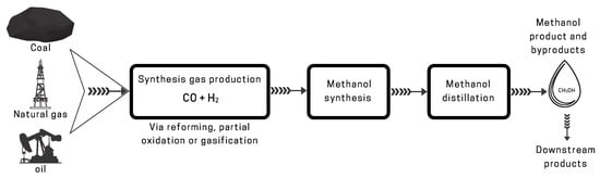
2.1. Traditional Methods

The commercial methanol production has a long history of almost 100 years, since 1923 at the BASF’s Leuna site [29]. Early developments have been extensively reviewed in the literature [29][30][31]. Nowadays, the production capacity for a large-scale methanol plant can reach up to more than 5000 metric tons per day [29] and mainly comprise of three processes: synthesis gas production, methanol synthesis and methanol distillation, as shown in Figure 2. The synthesis gas, which mainly contains CO, CO2, H2, H2O, some methane, inert gases and sulphur traces depending on the source, is predominantly produced by reforming of natural gas [32][33][34] or gasification of coal, with the latter especially used in China [22]. Other feedstocks for syngas production include liquefied petroleum gas, naphtha and biomass [33].
Figure 2. Schematic of the conventional methanol production process.
There is no doubt that syngas production is of great importance for a conventional methanol production both from technical and economical viewpoints. For instance, increasing the production capacity of a methanol plant requires a capacity expansion of the syngas production, where the main capital cost is associated with the reforming process [35]. Moreover, gas purification processes are usually involved in syngas production to avoid possible catalyst poisoning in the reforming process as well as the downstream methanol synthesis process. The reader is referred to the literature for the technical details of the different processes; reforming [33][35], coal gasification [36] and gas purification [37].
Nowadays, methanol is predominantly synthesized from the produced syngas using copper-based catalyst at operating pressures between 50–100 bar and operating temperatures of 200–300 °C, and involves the hydrogenation of CO and CO2 and reverse water–gas shift (RWGS) reactions as shown below [38][39]:

CO+2H2⇌CH3OHΔH298K=−91kJ/mol(1)

CO2+3H2⇌CH3OH+H2OΔH298K=−49kJ/mol(2)

CO2+H2⇌CO+H2OΔH298K=+41kJ/mol(3)

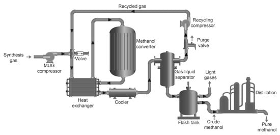
Due to the low one-pass conversion of COx (CO and CO2) to methanol of only about 5–15%, the recycling of the unconverted syngas is usually necessary with a recycle ratio of between 2:1 and 5:1 [39]. A typical methanol synthesis loop along with the sucessive distillation step is shown in Figure 3. Before entering the methanol synthesis process, the composition of the synthesis gas is adjusted, for instance by adding CO2 according to the stoichiometric ratios in reactions (1) and (2), resulting in a stoichiometric number SN = (mol H2 − mol CO2)/(mol CO + mol CO2), which is usually around 2 or slightly higher for methanol synthesis [32]. The synthesis gas after the composition adjustment is called makeup gas (MUG). A MUG compressor (or multi-stage MUG compressor) is usually required to fulfill the pressure requirement for the methanol synthesis process, for example, the produced MUG with a pressure of 50 bar and the methanol converter operated at 80 bar. After the MUG compressor, the syngas is mixed with the recycled gas, which then enters the methanol converter.

Figure 3. Schematic of a generic methanol synthesis process.
There are mainly two types of methanol converters for commercial methanol production, namely multiple adiabatic catalyst beds with external cooling and internal cooling within one or more catalyst beds [29][40]. The latter is more favorable for industrial methanol production as it provides a more even temperature distribution and lower hot spot temperature in the catalyst bed, while the former is simpler and less expensive [29]. The commercial catalysts based on CuO/ZnO/Al2O3 are widely used in methanol production [38], since they provide both high activity and selectivity of typically above 99.5% [29]. Nonetheless, there is still room for improvement of the catalyst performance in terms of activity, selectivity, stability, and durability [41]. Catalyst deactivation usually occurs due to the poisoning by the impurities in the system and due to thermal effects, such as sintering of the copper particles. The representative converter designs and catalysts for methanol synthesis are thoroughly reviewed in the literature [29][30][35][38][41].
The methanol produced in the methanol converter contains water, traces of higher alcohols such as ethanol, and dissolved synthesis gas [32][42]. Even though this crude methanol can be used directly for many applications, including producing Dimethyl ether (DME) [43] and biodiesel (when originated from biomass) [44], a distillation step is usually necessary to obtain methanol purity specifications required on the market, i.e, “AA” or chemical-grade methanol [42]. Distillation technologies are mature and 2 to 4 distillation columns are usually used in methanol plants. A three-column methanol distillation, i.e., a double-effect distillation scheme is commonly used in a large-scale methanol plant, where the light ends and dissolved gases are removed in the first column, and high-purity methanol is produced in the other two columns. This can save around 35% energy demand compared to a two-column distillation scheme but has a higher investment cost [32]. An additional column could be added based on the three-column scheme to further recover the methanol from the heavy components, such as water and ethanol, especially when there are more byproducts in the raw methanol due to the catalyst deactivation in the methanol converter. Energy demand is one of the main concerns for the methanol distillation process and further optimizations focusing on the distillation process, such as multi-effect distillation [45][46] and heat pump assisted distillation [47], as well as the heat integration with other parts of the methanol plant are possible to lower the overall energy demand.

2.2. Renewable Methanol

The methanol economy envisioned in this paper goes hand in hand with the hydrogen economy and takes into account the increasing renewable penetration around the globe. Hence, producing methanol from surplus electricity via power-to-X processes is of paramount importance for a sustainable future. Unlike in the traditional methods, where ‘black’ methanol is produced from natural gas, coal and oil; renewable methanol, also known as ‘green’ methanol is produced from renewable H2 and CO2 sources with net zero CO2 emission, such as hydrogen from renewable electricity [48] and CO2 from biogas or the atmosphere [49]. When methanol is produced from waste and byproducts, which are only renewable to a degree, it is referred to as ‘grey’ methanol [50].
In the direct conversion of CO2 to methanol (CTM) process, the conventional syngas production in Figure 2 is replaced by the production and compression of CO2 (or CO2-rich feed gas) and H2, which can be achieved by relevant technologies, i.e., water electrolysis, CO2 capture and biogas production, in the methanol plant or from other sites. The process can be based on the mature technologies of syngas to methanol (STM) described previously with appropriate adjustments at all the stages of the synthesis process. For instance, since the enthalpy of reaction for reaction (2)(ΔH298K = −49 kJ/mol) is less than that of reaction (1) (ΔH298K = −91 kJ/mol),
there is less requirement of heat removal for the CTM process, which indicates a possible lower operating temperature for the adiabatic converter and a larger diameter design of the reacting tube for the isothermal converter compared to those in the traditional STM process. Additionally, the tube-cooled reactor is also an option for this process [51]. Other novel reactors focusing on the in situ condensation and removal of the produced water and methanol, e.g., by using membrane reactors [39][52], sorption-enhanced [53][54] and natural convection [55] processes, are also reported at research level.
However, hydrogenation of CO2 to methanol by reaction (2) introduces more water, which has a detrimental effect on the conventional Cu-based catalyst [56]. There has been increasing focus on the improvement and development of catalysts for this process since the early 1990s [22][57][58][59][60][61]. Some of the new generation commercial catalysts with high activity and stability for application in the CTM process, include, MK-151(Topsoe), MegaMax 800 (Clariant) and KATALCO 51-100 (Johnson Matthey) [30]. However, further investigations of current catalysts and development of novel catalysts are still required for a large-scale commercialization of CTM processes [62].
Compared to the STM process, the raw methanol produced in the CTM process contains more water and less byproducts [51]. Pontzen et al. [63] found 5 times lower byproduct content for the CTM process compared to STM, which opens the possibility to simplify the first distillation column and decrease the load for the other columns, in which the separation between methanol and the byproduct ethanol is the main concern. A simpler distillation system with one column or two columns was reported by Carbon Recycling International (CRI), where a stripper unit was connected to the overhead section of the first column to remove the dissolved CO2 and other light end impurities [51]. It should be noted that the load of the distillation system can also be lower if the product methanol is for fuel blending, where the separation between methanol and the small amount of ethanol is not necessary according to the different standards for fuel methanol blends, including the EN228 for European Gasoline and M5–M100 for the Chinese market [17].
Besides the pathway of direct CO2 conversion to methanol, a two-step process named CAMERE (carbon dioxide hydrogenation to methanol via reverse water gas shift (RWGS)) has also been reported [64]. The aim of the CAMERE process is to convert part of the CO2 in the feed gas to CO before the methanol synthesis process, and consequently decrease the detrimental effect of water on the catalyst for methanol synthesis. A pilot plant that uses this process was built by the Korean Institute of Science and Technology (KIST) with a methanol production of 75 kg/day, and an operating cost of around 300 $/ton methanol was estimated [65]. Anicic et al. [66] compared the two-step CAMERE process with the one-step CTM process, both with two reactors, and showed a slightly higher energy efficiency and lower cost for the direct one-step CTM process. Modeling studies on the application of membrane reactors for the CAMERE process were also reported in [15][67].
Co-electrolysis using SOECs offer an interesting avenue towards higher CO2 to MeOH efficiencies [68][69][70]. H2 production using SOECs operated at 20 bar can reach about 96% conversion efficiency based on HHV [71]. Comparison with conversion efficiencies for AEC and PEMEC are provided in Table 1. Al-Kalbani et al. [72] modeled methanol production using high-temperature SOEC-based co-electrolysis of H2O and CO2. The production efficiency was found to be substantially higher for this system, than the production efficiency for a system based on water electrolysis and CO2 hydrogenation. Unfortunately, the conventional fuel electrode on SOECs contain Nickel, which catalyzes a part of the produced syngas into methane. Since a recycling ratio of 2–5 is normally required in the methanol synthesis loop [39], this means CH4 accumulates in the loop, which in turn reduces the methanol production in the catalyst reactor. Furthermore, the CH4 formation in the SOEC fuel electrode is favored by pressure [73]. This challenges syngas production based on pressurized co-electrolysis using conventional SOEC fuel electrodes.
Table 1. Process energy efficiency comparison between methanol and hydrogen as a source of fuel for fuel cell electricity production.
Step Energy Conversion Route Process Efficiency Reference
Methanol Hydrogen Methanol Hydrogen
1 Power Management, Conditioning and Transmission 90% [190]
2 H2 production by electrolysis PEMEC → 78% [191]
AEC → 74% [192]
SOEC → 96% [71]
3 Methanol synthesis H2 compression 79 (69–89)% 75 (65–85)% [83]
4 Fuel transportation 99% 95% [193]
5 Methanol Fuel cell system Hydrogen Fuel cell system 50% 60% [145][194]
A small amount of sulphur can be added to the SOEC inlet gas which reduces the CH4 formation activity to almost zero without sacrificing too much of the electrochemical activity [74]. Unfortunately, Sulphur also increases the sintering activity of Ni [75], which accelerates electrode degradation. This decreases the SOEC lifetime, thereby making Sulphur addition a less attractive approach.
Ni serves two purposes in the SOEC fuel electrode. It is catalytically active for H2O and CO2 reduction, and it conducts electrons to the electrochemically active sites in the electrode. Substituting the Ni with Cu is one way to avoid CH4 formation. However, the sintering activity is higher for Cu than for Ni, and the catalytic activity for H2O and CO2 reduction is higher for Ni than for Cu [76]. This leads to accelerated degradation and higher resistance if Ni is substituted with Cu. Sufficiently low Cu sintering can be obtained if the SOEC operation temperature is reduced to 500 °C [76]. However such a low operation temperature results in high internal resistance, which implies a high system CAPEX [68].
Graves et al. recently demonstrated an interesting electrode where the current collector is substituted with Sr0.99Fe0.75Mo0.25O3−δ (SFM), and the catalytic activity is obtained with Pr-doped CeO2 (CPO) nano particles [77]. Such an electrode could enable pressurized co-electrolysis of CO2 and H2O, without Ni or Cu sintering, and without CH4 formation.

2.2.1. Technology Status and Prospects

The CTM process is currently in the demonstration phase. A large-scale CTM pilot plant by CRI named after Nobel Prize laureate George Olah has been operating in Iceland since 2012 with a production capacity of 4000 tons per year of methanol, where the CO2 from the off-gas of a geothermal power plant and H2 from water electrolysis are converted to fuel grade methanol [51]. This is a way of exporting surplus renewable electricity in liquid form for an isolated country like Iceland with no electrical connections to neighboring countries but with abundant renewable electricity production, where the H2 production by water electrolysis benefits from the cheap electricity price [51].
Another pilot plant with a capacity of 100 tons per year located in Osaka was developed and built by Mitsui Chemicals and Research Institute of Innovative Technology for the Earth (RITE) in 2009 [30]. Early pilot-scale test plant with a production capacity of 50 kg methanol per day was also reported by RITE aiming at the development of efficient Cu-based catalyst for the CTM process [78][79]. Other pilot-scale plants include, a demonstration plant for a carbon-neutral synthetic fuel from carbon dioxide and hydrogen gases that uses a commercial catalyst from Johnson Matthey [80] and a CTM process by Lurgi/Air Liquide that uses commercial catalyst from Süd-Chemie (now Clariant) [63], where a stability test of 700 h has been carried out. In the latter, the catalyst showed good activity and selectivity and a deactivation rate similar to that of the STM process. Other pilot plants were also reported in ongoing projects, such as the Carbon2Chem project in Germany, which is working on the production of fuel methanol from steel mill gases [81], and the Power2Met project in Denmark, which is focusing on the production of biomethanol from biogas [82].
With respect to the commercialization of green methanol, the production cost is still a major obstacle and dominated by the cost of H2 production [30]. However, there is potential to further decrease the production cost by using surplus electricity for water electrolysis, optimizing the electricity consumption according to the fluctuations of electricity price and reducing the cost of electrolyzers [83].
Moreover, the cost of the green methanol can also benefit from the efforts to lower cost of CO2 capture technology in the future as well as the implementation of carbon taxes in more countries. Klenert et al. [84] reported that carbon pricing is a necessary and effective economic tool for reducing GHG emissions and tackling climate change but is challenged by low political and public acceptability, which they recommend can be enhanced by carbon revenue recycling. Even though more countries are committing or pledging to implement carbon tax, at the moment carbon trading only covers 20% of global GHG emissions, out of which less than 5% are priced at levels consistent with reaching the temperature goals of the Paris Agreement [85].
The adoption of carbon pricing is thought to be particularly challenging to some emission-intensive and trade-exposed industries, which may require government subsidies [84]. However, emission-intensive industries are also ideal sites for methanol production as they provide high concentrations of CO2, which is easier and cheaper to sequester. Therefore, if incentivized through appropriate carbon pricing and trading schemes, they can contribute to tackling climate change not only by sequestrating their own emissions but also by replacing transportation fuels and raw materials for the chemical industry with methanol and its derivatives.

2.2.2. Renewable CO2 Sources

The renewable CO2 and H2 for the production of green methanol can be obtained from various local sources. The widely reported renewable CO2 sources are air [49] and biomass [14], with the technologies for air CO2 capture still at a research stage [49]. The biomass sources mainly include industrial and municipal waste, forestry and agriculture (including their residues) [14], where the biogenic CO2 is produced as a byproduct with different concentrations, e.g., 40 vol% of CO2 from a biogas plant and 85 vol% CO2 from a bioethanol plant [86]. Clean and high purity of CO2 can be obtained by purification technologies, such as H2S removal by physical and chemical absorption [87], and CO2 capture technologies, including amine-based post-combustion capture and cryogenic separation [49]. Additionally, since biogas contains high concentrations of CH4 and CO2, other processes, such as dry reforming [88] or bi-reforming [89], with the latter offering better catalyst stability, and co-electrolysis in solid oxide electrolyzer (SOEC) [69][70][90] can be employed to directly produce syngas.
Since carbon-intensive industries play an important role in the global economy, CO2 capture and storage (CCS) technologies are identified by the International Energy Agency (IEA) as the only option for deep CO2 reduction for many industrial production sectors and equipping these industries with CCS was found to be the cheapest pathway for tackling global climate change to limit temperature rises to the 2 °C scenario [91]. It has been reported that despite the high cumulative energy demand for CCS, it ultimately results in a substantial lifetime GHG emission reduction of fossil fuel-based power plants, with up to 84% reduction at 90% CO2 capture efficiency [92]. However, in the short term, due to their high energy-intensive nature, lack of clear business plans and an adequate CO2 tax system that penalizes the emitters, the real life use of CCS systems is very limited [93]. CCS systems consist of different separate processes: post-combustion, pre-combustion or oxy-fuel CO2 capture process, followed by a separation, transportation and storage processes, with the CO2 capture process accounting for around 70–80% of the total cost [93].
Even though there are no financially attractive CCS systems currently, due to the costs associated with the increased energy demand that lowers the overall energy production efficiency, utilization of the captured CO2 for economically productive applications could offset some of the costs [93]. Methanol production could be one such application, and when produced onsite, whereby CO2 storage and transportation are avoided, the process can become economically attractive. Pérez-Fortes et al. [94] performed a techno-economic and environmental assessment of methanol synthesis using captured CO2 as raw material. They found that the total CO2 demand is 1.46 tCO2/tmethanol with a net potential for CO2 emissions reduction of 2.71 MtCO2/year in Europe, assuming that the carbon capture and utilization (CCU) plants are built in Europe to meet methanol demand growth and the quantities that are currently imported. They also reported that the project is not financially viable due to the high cost of H2 and CO2.
However, with increased renewable electricity penetration and advancements in both electrolysis technology and methanol synthesis techniques, and appropriate carbon tax schemes, CCU for methanol synthesis could soon become profitable. Besides, the main carbon storage solution, namely, geological CO2 storage in unmineable coal beds, saline aquifers and in the deep ocean can result in potential leakage of the stored CO2 with hazardous consequences to the environment, including acidification, eutrophication, pollution and toxicity [93][95].

2.2.3. Renewable H2 Sources

Another ingredient of the methanol synthesis process is H2, which is increasingly recognized as a clean and renewable energy carrier that is expected to play an important role in the fight against global warming and other environmental problems caused by fossil fuel combustion [96][97]. Majority of H2 is currently produced from natural gas via the reforming process. However, renewable ways of obtaining H2 are available, including water electrolysis via renewable electricity, such as solar photovoltaic (PV) and wind turbines, potentially offering grid balancing services as well [98][99][100][101]. Hydroelectric energy [102], ocean thermal [103][104] and geothermal energy [105][106] could also be utilized to produce hydrogen sustainably. Even though the cost-benefit analysis favors reforming over renewable sources [107], considering the current urgency to climate action, it is important to move towards renewable ways of producing hydrogen. Once produced, the hydrogen can then be stored as a compressed gas, as a cryogenic liquid, in metal hydrides or converted into electrofuels, including methanol and then utilized again to produce electrical energy and heat [108][109][110][111].
The history of water electrolysis stretches back to the first years of electricity discovery more than 200 years ago when Alessandro Volta invented the voltaic pile in 1800 showing that electricity can be produced by chemical reactions, and few weeks later William Nicholson and Anthony Carlisle used it for electrolytic splitting of water [112]. In 1888, Dmitry Lachinov developed a technique for industrial water electrolysis, which resulted in more than 400 industrial water electrolyzers in operation already by the year 1902, and development of the technology continued, mainly driven by the industrial hydrogen and oxygen demand, with the first large plant with a capacity of 10,000 Nm3H2/h established in 1939[112][113]. In water electrolysis, electricity (direct current (DC)) is used to split water into its components, H2 and O2 according to the following overall reaction:

H2O(l)−→−−−electricityH2(g)+12O2(g).(4)

The reaction happens electrochemically on two electrodes separated by an electrolyte, where the oxygen evolution half cell reaction (OER) takes place on the anode side and hydrogen evolution half cell reaction (HER) on the cathode side.
The most common types of electrolyzer cells, based on the electrolyte materials they employ and their operating parameters are: solid oxide electrolysis cell (SOEC), alkaline water electrolysis cells (AEC), and polymer electrolyte membrane electrolysis cells (PEMEC) [114]. SOEC is the most efficient of the three cell types as the electrical demand decreases with increasing operating temperature due to favorable thermodynamics [115]. However, the high operating temperature also means more stringent material requirements and long-term stability issues [116][117]. As already mentioned, SOEC can also be use for co-electrolysis of steam and CO2 to produce syngas [90].
The alkaline water electrolyzer is the most mature technology among the three with some advantages in structure and cost and it is suitable for large-scale hydrogen production. It uses a liquid electolyte of 20–40 wt. % concentration of either NaOH or KOH and operates between 70–90 °C at below 3 MPa [115]. However, disadvantages such as higher energy consumption, lower efficiency, strongly corrosive environment, and limited capability to work at high pressure due to gas cross-over restrict its further development [118][119].
Compared to the other types of water electrolyzers, PEM water electrolyzer stands out among other things for its higher hydrogen production rate, higher current density, higher gas purity (above 99.99%), low gas permeability, wide dynamic operation range, compact design, and rapid response [120][121][122][123]. AEC and SOEC based systems combined with purification can achieve similar high gas purity, but AEC still suffers from the above mentioned limitation and SOEC requires further development. Therefore, PEM water electrolysis is considered a promising technology to generate hydrogen from renewable and fluctuating electricity. However, the corrosive acid environment at a pH of around 2 and high applied voltage, especially at high current densities require highly resistant and costly materials, namely noble metals, such as Pt, Ir, and Ru for the catalyst, and titanium for the current collectors and separator plates [120]. These metals are scarce on the Earth’s crust, especially the noble catalysts, with Ir or IrO2, which are currently the catalysts of choice for the anode side OER, being the scarcest of them. Prices for these metals are bound to further increase with the commercialization of electrolyzers, fuel cells, and other electrochemical devices. Hence, research on reducing the catalyst loading and using new materials is ongoing to reduce the cost of PEM electrolyzers [120][124][125].
Water photoelectrolysis, also known as Photoelectrochemical (PEC) water splitting, is another renewable way of producing hydrogen, which employs solar energy to decompose water [126][127][128]. In order to better absorb the sunlight radiation for efficient hydrogen production, studies on new semiconductor materials with the properties of super stability, high photocatalytic activity, and visible light absorption are crucial [127]. At the moment, it is still challenging to balance the cost of the materials and infrastructure for large-scale photoelectrolyzers and the hydrogen production rate of the system. Therefore, more effort is needed to reach a reasonable solar-to-hydrogen efficiency and achieve practical and economical hydrogen production with this process [128].

3. Methanol Use

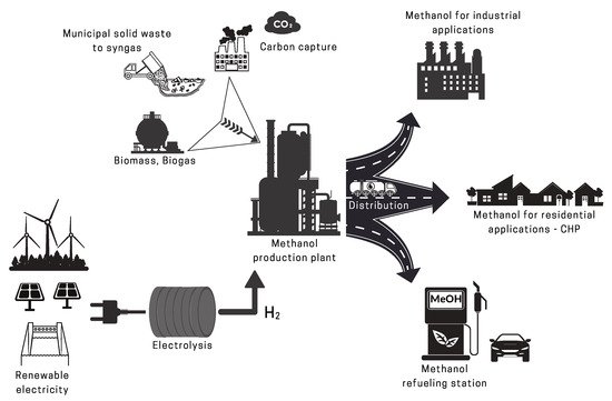
Methanol is already one of the most important and widely traded chemical commodities, and its demand is growing rapidly with a compound annual growth rate (CAGR) of 6% between 2014 and 2019 [17]. This is mainly due to its versatility and the numerous industrial sectors it serves. As shown in Figure 4, it not only can be produced from various feedstock, but can also be used in several applications. In the following sections, an overview of its use in the chemical industry and the energy sector is given. Even though it is still extensively used in the chemical industry, this review focuses on its use in the energy sector, especially in fuel cells, as it investigates methanol as a renewable energy carrier.

Figure 4. The methanol value chain. Adapted from [30,129].

3.1. Methanol in The Chemical Industry

The chemical industry has long relied on fossil fuels for its processes. However, a transition driven by climate goals is underway to make the chemical industry more sustainable, both its raw materials and energy demand. Even though methanol is predominantly produced from fossil sources at the moment, the plethora of methanol chemical derivatives and products pave the way for a green methanol-based chemical industry. The fact that it is already one of the most important chemical commodities also makes it an ideal candidate for this transition and can help integrate fossil raw materials and biomass value chains [30].

For instance, lower C2–C4 olefins (ethylene and propylene) that are normally produced from crude oil and are the most important monomers for further petrolchemical and chemical synthesis processes can be produced from methanol [24]. The process of manufacturing lower olefins from methanol takes place on a mesoporous H-ZSM-5 zeolite catalyst at high temperatures of around 370–500 °C, a process that started in the late 1970s by Mobil Oil Corporation, with other similar processes that use different catalysts available in many plants around the globe today [24]. Moreover, methanol can also be used as a solvent and/or additive in various sectors, such as paint removers, wind-shield washers and it can be used as a fermentation substrate in microbial productions [17].

3.2. Methanol in Energy Systems

In recent years there has been a paradigm shift in the use of methanol. As recent as 2012, 85% of the methanol production was used in the chemical industry [22]. However, this is rapidly changing and the use of methanol in the energy sector now accounts for 40% of methanol consumption [17]. Below some of the uses of methanol in the energy sector are discussed.

3.2.1. Methanol in Internal Combustion Engines

Methanol possesses some interesting properties that make it more performing compared to conventional fuels for internal combustion engine; high latent heat, fast-burning velocity, no carbon to carbon bonds, and high octane rating, and hence higher compression ratios and higher knock resistance for an increased engine efficiency [25,130]. In fact, its use in engines has been studied as far back as the beginning spark-ignition engines, where methanol was investigated for enhancing the engine performance [130]. Moreover, with its clean-burning and less explosive nature, methanol is the fuel of choice in most competitive motorsports, both due to its high performance and safety compared to other fuels [12,131]. However, methanol is corrosive to some metals and can cause swelling of rubber and plastic components, which calls for proper corrosion inhibitors and swelling resistant seals in methanol-based engines.

Despite its early use in internal combustion engines, it was only in the 1980s and 1990s with the California methanol fuel trials that its use as an alternative fuel in internal combustion engine was demonstrated at a larger scale, where 15,000 M85 (85% methanol) gasoline flex-fuel vehicles of various applications were operated [130]. The program started to reduce NOx emissions, mainly to prevent ozone depletion [132]. Even though the experiment was a technical success it was slowly abandoned in 2004, mainly because natural gas, which was the main source of methanol for the trails, was thought to be scarce and expensive at the time, which was later proven wrong with possibility of nowadays selling methanol from natural gas at half the price of gasoline [133]. Moreover, the oil companies came up with cleaner gasoline by blending it with Methyl Tertiary Butyl Ether (MTBE) to meet california’s demands, which however required methanol for its production and diverted it from being used as a substitute to gasoline [133].

China, which is rich in coal but heavily relies on imported oil for its transportation sector, has recently decided to use methanol nationwide as a transportation fuel to tackle both energy security and air pollution challenges [18]. Driven by coal mining permits the Chinese methanol production from coal gasification has reached a production capacity able to cover half of China’s transportation fuel demand [130]. Similarly to the California trials of the 1990s, a methanol vehicle pilot program was conducted between 2012 and 2018 in 10 Chinese cities, where more than 1000 methanol vehicles were tested [18]. The program showed methanol’s feasibility as a viable transportation fuel with neither techno-economical nor safety issues, and today there are several hundreds of thousands of vehicles that run on pure methanol or methanol blends, including retrofitted vehicles [18]. Despite the coal mining pretext for the methanol production in big quantities in China, the fact that there are no major technical barriers to its use in internal combustion engines and its other numerous applications along with the increasing urgency for climate actions could lead to more investments and progress in renewable methanol production worldwide and establish it as the fuel of the future.

The International Maritime Organization (IMO) has set a new limit in which all sizes of ships will need to use fuel that meets the 0.50% m/m (mass by mass) SOx emissions from 1 January 2020, lowering it significantly from the current limit of 3.50% m/m for ships operating outside designated emission control areas [134]. Moreover, there is a plan to cut GHG emissions from international shipping in half by 2050 and successively eliminate them entirely [135]. These increasingly stringent emission limits and the fact that methanol is transported in huge amounts in ships is driving an increasing interest in the use of methanol for marine applications as well. At the moment there are a number of projects to test methanol-fueled vessels, including seven new dual-fuel engine chemical tankers, a retrofitted Stena Line ferry, a pilot boat by ScandiNaos, two retrofitted HT-PEMFC tourist boats and others research and development projects [136].

Recently, a study by A.P. Moller - Maersk and Lloyds Register identified alcohols, such as methanol and ethanol, along with biomethane and ammonia as the three main fuels to achieve a net-zero CO2 emissions in the shipping industry [137]. They concluded that alcohols that can be produced from renewable hydrogen and CO2 from biomass or carbon capture have the advantage as they can use proven existing solutions for handling the low flash point and burning and are fully mixable in the vessel’s bunker tanks, creating bunkering flexibility.

Similarly, electrofuels can play an important role in decarbonizing aviation [138]. Goldmann et al. [11] investigated five electrofuels, including methanol for use in aviation and found that they can generally replace conventional kerosene-based fuels, but suffer from higher structural loads and potentially lower efficiencies. Moreover, kerosene-based fuels for international aviation remain tax-exempt due to Air Service Agreements (ASAs) made soon after the second world war [138]. Hence, for electrofuels to compete with kerosene-based fuels for aviation, the introduction of such taxes and more stringent fuel standards are required along with carbon pricing and increase in renewable electricity share for cheaper green hydrogen.

3.2.2. Methanol in Fuel Cells

In fuel cells, methanol can be used either directly in direct methanol fuel cells (DMFC) or indirectly via methanol steam reforming into hydrogen-rich gas mixture in HT-PEMFCs. The two fuel cell types are described below.

Direct Methanol Fuel Cells (DMFC)

A direct methanol fuel cell is a variant of proton exchange membrane fuel cells (PEMFC) that use liquid methanol and water mixture instead of hydrogen to generate electricity via electrochemical reactions. This gives DMFC the advantage in terms of fuel handling as liquid mixture can be used without the complications of the hydrogen storage required in the case of low-temperature PEMFC or the added reforming system needed in HT-PEMFC systems. The reactions in a DMFC are given below:

Anode:CH3OH(l)+H2O(l)⟶CO2(g)+6H++6e−(5)

Cathode:32O2(g)+6H++6e−⟶3H2O(l)(6)

Overall:CH3OH(l)+32O2(g)⟶CO2(g)+2H2O(l).(7)

DMFCs are suitable for portable power generation due to their power range and rapid refueling characteristics [139]. Consequently, they are usually investigated to replace rechargeable batteries in portable applications. However, there are some practical issues, including their low efficiency of below 30% due to methanol cross-over through the membrane that limit their widespread application [140,141]. High methanol cross-over also means that the fuel cell exhaust contains methanol and possibly formaldehyde, which can cause health concern. To minimize the cross-over the fuel cell should be kept fully hydrated, which requires it to be humidified on both the anode and the cathode side, thereby adding system complexity, limiting the operating temperatures and lowering the achievable electrical efficiency. Moreover, there has been a mismatch between the pace at which they have been developing and the industry’s need for readily available solutions, which were met by advances in lithium-ion batteries and efficient microprocessors.

Recently, DMFCs have also been investigated for unmanned aerial vehicle (UAV) applications due to methanol’s high energy density [142,143,144]. However, their lower efficiency and lower power density means that higher methanol volume is needed for longer flight time, which inevitably compromises the UAVs payload.

High Temperature PEM Fuel Cells (HT-PEMFC)

Contrary to DMFCs, reformed methanol fuel cells are an efficient way of using methanol to produce energy, with up to 50% overall electrical efficiency [145]. A reformed methanol fuel cell (RMFC) or a high temperature PEM fuel cell (HT-PEMFC) is a proton exchange membrane fuel cell that operates at temperatures above 100 °C, typically between 160 °C and 180 °C. However, unlike low-temperature PEM fuel cells, it does not require liquid water for the proton conduction through the membrane. To achieve appropriate proton conduction at temperatures above the boiling point of water, it employs polybenzimidazole (PBI) membrane, able to conduct protons under anhydrous conditions when doped with phosphoric acid. Therefore, the need for reactant humidification and the associated water management that is crucial in low-temperature PEM fuel cells is eliminated, thereby avoiding the risk of cell flooding or drying. The reactions that take place in an HT-PEMFC are the same as those of a low-temperature PEM, and are given as follows:

Anode:2H2(g)⟶4H++4e−(8)

Cathode:O2(g)+4H++4e−⟶2H2O(g)(9)

Overall:2H2(g)+O2(g)⟶2H2O(l).(10)

The higher operating temperature of HT-PEMFC comes with an added advantage of higher tolerance to impurities in the fuel compared to their lower temperature counterparts [146,147,148]. In fact, it is possible to use the product gas of methanol steam reforming, known as reformate gas (H2, CO2, and traces of CO and unconverted methanol-water mixture) directly in the fuel cell without any pre-purification, giving HT-PEMFCs big advantages in terms of fuel flexibility [149]. A comprehensive review of the core PBI-based HT-PEMFC technology and its components and their characterization can be found in our previous work [150]. Therefore, the focus of this review is not on the core HT-PEMFC technology but rather on the whole system and its role in the methanol economy.

A reformed methanol fuel system with all its main components is shown in Figure 5. The process starts in the catalytic burner, which uses some of the fuel to heat up the reformer. In the reformer, steam and methanol fed through an evaporator are heated up further to produce the reformate gas, which is then directed to the fuel cell to produce electricity. The evaporator recovers heat from the fuel cell stack exhaust air and coolant. In some cases the reformate gas can be cooled down in a separate heat exchanger to reach the fuel cell stack operating temperature. Once the systems is started, the reformate exhaust from the anode off-gas can be recycled in the burner.

Figure 5. A schematic of a reformed methanol fuel cell system.

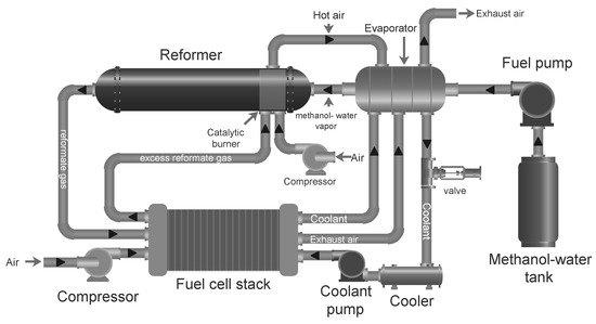
As can be seen in Figure 5, HT-PEMFC systems have the possibility of heat integration of hot and cold streams, where at least two reactors which require heat can be identified, i.e., the endothermic methanol steam reformer and the evaporator. On the other hand the fuel cell stack and the burner release heat, although the fuel cell stack requires heat during system start-up in order to reach operating temperature. In [151], a strategy to ensure proper heat integration over all the load ranges was suggested. The principal idea is to provide extra fuel to the burner whenever the heat provided by the depleted fuel and air at the stack outlets is not sufficient. It was found that below a certain load, anode stoichiometric ratio must be increased in order to provide enough heat to the burner to sustain both the reforming and fuel cell reactions. In other words, the amount of fuel mix that is sent to the fuel cell stack must be larger than what is strictly required for the electrochemical reactions to take place.

An alternative strategy for the warming up of the stack during the start up phase was investigated in [152], where alternating current is applied directly to the stack with a suitable frequency aimed at heating the stack’s main ohmic resistances (i.e. membrane and contact resistance). The strategy was found to reduce the start-up time compared to more conventional strategies based on external liquid coolant.

The use of different fuels requires different heat integration strategies and can affect the electrical efficiency of the system. In [151], it was shown that in an ideal case a methanol-fed system shows a better efficiency compared to a hydrogen-fed system. This can be attributed to the fact that in the system with the methanol reformer, the heat in the depleted gas at the stack outlet can be reused for the endothermic reforming process. However, it is worth noting that even though HT-PEMFC has a higher tolerance to CO in the reformate mixture, this can still reduce the cell performance and lifetime compared to a hydrogen-fed system.

Methanol Reforming

The process of catalytically converting hydrocarbons into a hydrogen-rich gas mixture is known as reforming. The process requires an oxidizing agent and if water vapor is used for this purpose, the process is known as steam reforming, which is endothermic and requires permanent external heating to be sustained. If on the other hand, air is used as the oxidant the process is an exothermic one called partial oxidation, whereas if both water and air are used the process is called autothermal reforming, which is a combination of the two processes with net reaction enthalpy change of zero [153].

Methanol, which is the simplest alcohol with only one carbon atom has one of the lowest reforming temperatures of only 200–300 °C owing to the absence of a strong C–C bond [154,155]. The single carbon configuration gives it a high H/C ratio of 4:1, which results in high concentration of H2 in the reformate mixture for use in an HT-PEMFC. It is also liquid at ambient conditions with a boiling point of around 65 °C and completely miscible with water, and hence, easy to store and transport [22]. The most widely used reforming process in conjunction with HT-PEMFCs is methanol steam reforming (MSR) as it produces high concentration H2 per mole of methanol according to reaction (11), which is an algebraic sum of the water gas shift reaction (WGS) in reaction (12) and the methanol decomposition (MD) in reaction (13) [154,156,157].

MSR:CH3OH+H2O⇌CO2+3H2ΔH298K=+49.7kJ/mol−1(11)

WGS:CO+H2O⇌CO2+H2ΔH298K=−41.2kJ/mol−1(12)

MD:CH3OH⇌CO+2H2ΔH298K=+90.2kJ/mol−1(13)

Copper-based catalysts, such as Cu/ZnO/Al2O3 are currently the most widely used commercial catalysts for hydrogen production for fuel cell systems with relatively good activity and selectivity, where Cu acts as the active component [158,159,160]. The reforming activity on Cu/ZnO/Al2O3 starts at 160 °C [156], which would be ideal from a system integration point of view with an HT-PEMFC that typically works between 160–180 °C. However, even at around 200 °C around 8% of unconverted methanol slip can be present in the reformate mixture, an amount that is detrimental to HT-PEMFC’s performance and lifetime [161,162]. Therefore, it is only above 230 °C that a steam methanol reformer can produce a clean enough reformate mixture (≤2% methanol and ≤1% CO) that is usable in an HT-PEMFC without a cleanup process and without compromising the performance and durability of the fuel cell.

The CO concentration in the reformate mixture increases with increasing reforming temperature, while the unconverted methanol concentration decreases due to higher conversion rates at higher reforming temperatures. However, even though the harmful effect of CO on performance increases with increasing CO concentrations, an HT-PEMFC can tolerate higher CO concentrations of up to 5% with only small performance decay, especially at higher operating temperatures and lower current densities [150]. In comparison, low-temperature PEM fuel cell can only tolerate a few parts per million of CO concentrations in the anode feed. Nonetheless, the lower the CO concentrations in the reformate mixture the better it is for the fuel cell both in terms of performance and durability.

Therefore, since methanol slip and CO concentration have opposite trends with respect to reforming temperature, an optimal reforming temperature and proper control of the flow rates are required to obtain a proper reformate mixture. An experimental mapping of the methanol and CO concentrations in the reformate gas with respect to reformer temperature at the inlet are shown in Figure 6 [161].

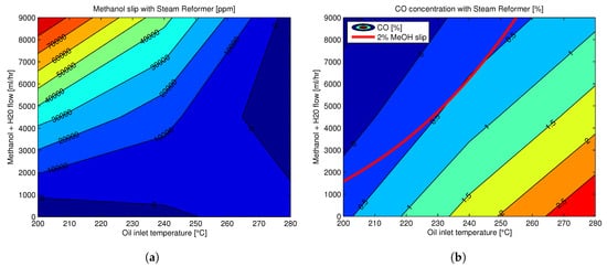
Figure 6. Reformate composition at the steam methanol reformer outlet at different reforming temperatures (given by the temperature at the inlet of the reformer) (a) Methanol concentration in reformate mixture at different reforming temperatures (b) CO concentration in reformate mixture at different reforming temperatures, with the red line showing the 2% methanol slip. Reprinted with permission from [161]; 2016, Aalborg Universitetsforlag.

In order to limit concentrations of undesired byproducts, including unconverted methanol in the reformate gas, catalysts for steam reforming should have high activity and fast kinetics at low temperature, high selectivity in order to suppress CO production, and good stability, and long lifetime [163]. Moreover, catalysts with well-dispersed and smaller crystallite size particles and higher specific surface area of copper generally result in better performance [164]. An extensive review of the influence of catalyst components and preparation methods on the performance of different Cu-based catalysts for MSR can be found in [163].

Catalyst deactivation generally happens due to thermal sintering above 300 °C with recommended operating temperatures of below 260 °C [164]. Coke deposition due to iron or other transition metals, wax or carbon formation due to silica reaction with alumina, and catalyst poisoning with sulfur and chloride content in the reactants are other deactivation mechanisms that have been observed for such catalysts in methanol steam reforming [165]. In order to maintain the chemical and thermal stability of Cu/ZnO-based catalysts in industrial application, Al2O3 or other substitutes are often added as stabilizers or promoters [165,166].

To overcome the problem of active phase sintering, the metals in groups 8 to 10 of the periodic table have also been studied as catalysts with higher thermal stability and similar selectivity compared to Cu-based catalysts [163]. Moreover, increasing the steam to carbon ratio in the feed of methanol-steam mixture decreases the catalyst deactivation rate [167], since the absence of water vapor can lead to coke formation that in turn can block catalyst pores and exacerbate their deactivation [168,169].

Conventional packed-bed reformers use catalysts in the form of pellets due to relatively low cost of preparation and ease of operation [170], despite being characterized by larger thermal gradient between the tube wall and the interior catalyst bed [155]. Recently, advanced micro-processing is making it increasingly possible to manufacture well-structured micro-channel reactors with wall-coated catalysts, which present fewer heat and mass transfer limitations [154]. Catalytic membrane reactor (CMR) with palladium-based membranes is another novel technology with improved process efficiency, where methanol steam reforming occurs on the tube side and hydrogen is permeated through a membrane and continuously collected on the shell side allowing to shift the reaction equilibrium towards the products, thereby improving methanol conversion [171].

HT-PEMFC Technology Status and Prospects

Reformed methanol fuel cells, like all fuel cells, are scalable and versatile and can be used in a variety of applications. They are investigated for stationary application; such as backup power for telecom application [145], uninterrupted power unit (UPS) [172], combined heat and power (CHP) generation for residential applications [173], and for portable power generation; as well as in automotive applications, both as auxiliary power units (APU) [172] for boats and road vehicles [174] and as range extenders [175,176].

A number of projects at demonstration and some at commercialization level have shown the potential for reformed methanol-fueled HT-PEM fuel cells in different applications. In automotive applications, reformed methanol fuel cell systems have been predominately used as range extenders in combination with batteries. In the European project ARTEMIS [177], the possibility to use a HT-PEM power train on a light-duty, commercial vehicle was investigated. Another example is in the danish municipality of Aalborg, where a methanol filling station was opened in 2015 to refill methanol fuel cell cars including a prototype of a Fiat 500 powered by a 5kW HT-PEM Stack, developed ad hoc for the demonstration project [175]. Recently, a Denmark-based company Blue World Technologies has started the development of a methanol-fueled HT-PEM fuel cell system for automotive application [178]. The company is betting on the technology and has a partnership with a Chinese electric vehicle manufacturer AIWAYS to supply the market with methanol fuel cell cars [176].

In the maritime sector, a project by the name e4ship funded by the German government demonstrated a 90kW system based on a methanol HT-PEMFC stack on the ferryboat Mariella from the Viking line. The system compromises 5KW fuel cell modules with methanol-reforming units for conversion of methanol into hydrogen [179]. In another demonstration project in the municipality of Essen in Germany a touristic vessel on the Lake Baldeneysee was powered by a 35 kW HT-PEM fuel cell system fueled by methanol [180]. For both these projects the fuel cells were developed by the Denmark-based fuel cell manufacturer SerEnergy.

HT-PEM fuel cells for residential CHP applications have also seen some development in the past few years. Demonstration projects have mainly used natural gas as a fuel for the already available distribution infrastructure. With little adaptation of the reforming process, these systems can operate with a variety of fuels, including methanol. Besides, HT-PEM fuel cells have the advantage of providing high-quality heat, which matches with the residential application requirements. In the Eurostars project HyRIS a micro CHP system was developed by the Germany-based Fuel Cell Research Center, ZBT, and the company Advent Technologies in Greece [181]. In another European demonstration project called ene-Field more than 1000 CHP units, including HT-PEMFC-based ones, have been tested in 10 European countries in the years between 2012–2017 [182]. The HT-PEMFC systems for residential use in this project delivers 300 W electric power and 600 W thermal power, where the small energy output offers cost-saving compared to the conventional energy supplier [183].

In UPS applications, methanol-fueled HTPEM systems are developed and commercialized by Serenergy [172]. The systems are targeted mainly for telecom applications in remote regions where conventional diesel generators are currently used.

For the commercial success of HT-PEMFCs, further development of more resistant materials and improved system integration and control designs are necessary to increase their lifetime. Bipolar plates with excellent corrosion resistance, low bulk density and high electrical conductivity [184], and methanol steam reformer which maximizes the heat transfer with a uniform flow distribution and low-pressure drop [185], are significant to reduce the balance-of-plant component number, size, mass, and ultimately cost.

The efficient heat integration is another key issue that needs to be addressed. An integrated stack-reformer system was demonstrated by Pan et al. [186] but with low hydrogen yield due to the lower operating temperature of the reformer at 200 °C. Ji et al. [187] tested an internal reforming fuel cell (IRMF) with methanol solution and air and achieved power density of 0.45–0.55 W/cm2

at 180–200 °C. However, they reported instability of the single cell at high current density.

Lotrič et al. [146] compared the heat-integrated systems capable of producing 25 W of gross electric power for use in portable applications. The results indicated that the system of integrated HT-PEMFC stack and methanol steam reformer was feasible and had higher system efficiency than the system with LT-PEMFC stack. Ribeirinha et al. [147] studied the thermal integration of a low-temperature methanol steam reforming cell with an HT-PEMFC in a combined stack arrangement. In addition, the degradation of the membrane electrode assembly (MEA) due to the methanol in the reformate stream was observed and investigated by using EIS analysis.

This entry is adapted from the peer-reviewed paper 10.3390/en13030596

This entry is offline, you can click here to edit this entry!