2. Nanomaterials
Nanomaterials, i.e., materials that possess at least one dimension less than 1 μm, have gained much attention in the scientific community since the past few decades. They have found an application in LHTES as well. Nanomaterials are added to PCMs to form composite nano-enhanced phase change materials (NEPCMs) with improved thermal conductivity. The following types of nanomaterials are used to prepare NEPCMs: metals, metal oxides, and carbon-based materials. Generally, their thermal conductivity is higher than the PCMs, and therefore they are treated as TCEs. Although nanomaterials can increase the thermal conductivity of PCMs, they also affect the other properties of the PCMs, which is overlooked in the vast majority of the papers. Therefore, there is a necessity to conduct a more complex analysis of the properties of NEPCMs, which has been undertaken in this paper.
Before discussing the properties of NEPCMs, it should be noted that the addition of nanomaterials (or the other thermal conductivity enhancers) into PCMs does not change the PCMs’ intrinsic properties, e.g., thermal conductivity, latent heat, etc. because the chemical composition of the PCMs remains unchanged. However, composite PCMs can be treated as homogenous materials with effective properties, which means that the properties of such composite materials are somehow a combination of the properties of pure PCMs and additives. Therefore, each time properties of composite materials are presented in this paper, it is referred to as their effective properties.
Thermal conductivity, latent heat, and melting temperature of NEPCMs are usually investigated by the researchers. A summary of such results is shown in
Table 2. Thermal conductivity enhancement was calculated according to Equation (2):
where n, k
eff, and k
PCM are the thermal conductivity enhancement, the thermal conductivity of NEPCMs, and the thermal conductivity of pure PCM, respectively. Generally, NEPCMs possess higher thermal conductivity than pure PCMs. Maximum improvement, up to 3.36 times, was obtained by Wang et al.
[9], who added expanded graphite (EG) into the octanoic acid/myristic acid mixture. In the case of metal-based and metal oxide-based nanomaterials maximal improvement was 1.86 times for paraffin wax
[10] and 1.79 times for paraffin wax
[11], respectively. The improvement of thermal conductivity depends mainly on the mass or volume fraction of the nanomaterial added into a PCM (detailed data about the PCMs and their thermal conductivity enhancers discussed in this section are shown in
Table 2). However, the results of the research on this issue are inconsistent. Some researchers indicated that the thermal conductivity increases linearly with increasing nanoparticles fraction
[12][13][14][15][16]. While others showed that the progression is nonlinear and the improvement starts to drop after reaching a certain value
[10][17][18][19][20][21]. The results obtained by Soni et al.
[12] are in the first group, but they were achieved by using numerical calculations. Hence, there is a necessity to conduct experimental studies to confirm the results. He et al.
[22] found in their experimental investigation that the thermal conductivity of NEPCMs increased linearly in a liquid phase. In a solid state the improvement for nano-graphite (NG)/PCM was also linear, but for graphene nanoplatelets (GNP)/PCM and multi-walled carbon nanotubes (MWCNT)/PCM there was saturation tendency, caused by agglomeration or sedimentation of the nanoparticles. The agglomeration of the nanoparticles was also reported in
[16][17][19][22]. As a result, the thermal conductivity of NEPCMs with high fraction of the nanoparticles started to decrease. Therefore, dispersion stabilizers are used, like: sodium stearoyl lactylate
[11], sodium dodecyl benzene sulfonate
[14], polyvinyl pyrrolidone
[20][23], and oleoyl sarcosine
[24]. Some studies
[9][12][17][19][20][22][25] investigated the insertion of different types of the nanomaterials into one PCM. The results of
[12][20][25] indicated that the thermal conductivity of NEPCMs increased with increasing thermal conductivity of the nanomaterials. On the other hand, the results obtained in
[9][17][19][22] do not confirm the abovementioned one, because the thermal conductivity improvement was not the highest for the highest-thermal conductivity nanomaterial. This indicates, that the improvement depends not only on the thermal conductivity of the nanoparticles, but also on their effective concentration
[17], the nature of fractal structures, aggregation dynamics, and variation in Kapitza resistance
[19], as well as the method of preparation
[24].
Table 2. Properties of nano-enhanced phase change materials (NEPCMs).
| Reference |
PCM |
Additive |
Additive Fraction |
Melting Temperature, (°C) |
Latent Heat, (kJ/kg) |
Thermal Conductivity (W/(m∙K)) 1 |
Maximum Thermal Conductivity Enhancement, (Times) |
| PCM |
NEPCM |
PCM |
NEPCM |
PCM |
Additive |
Liquid |
Solid |
| Sami and Etesami [11] |
Paraffin 4 |
TiO2 |
3 wt.% |
58.9 |
56.0 |
137.8 |
167 |
0.08 (l)
0.147 (s) |
n.a. |
1.79 |
1.34 |
| Lin and Al-Kayiem [10] |
Paraffin wax 4 |
Cu |
2.0 wt.% |
60.42 |
57.81 |
184.2 |
157.3 |
0.172 |
401 |
1.86 3 |
| Ali et al. [15] |
Paraffin wax 4 |
Nano graphene |
3 wt.% |
29.83 |
28.12 |
230.08 |
216.10 |
0.123 (l)
0.185 (s) |
n.a. |
2.46 |
n.a. |
| Aslfattahi et al. [26] |
Paraffin wax 4 |
Ti3C2 |
0.3 wt.% |
69.8 |
71.7 |
110.68 |
99.53 |
0.197 (s) |
n.a. |
1.16 3 |
| Zhu et al. [27] |
Paraffin wax 4 |
a-CNT |
7 wt.% |
47.36–58.84 |
46.72–57.02 |
196.47 |
218.56 |
0.24 |
n.a. |
n.a. |
2.33 |
| r-CNT |
15 wt.% |
45.82–56.84 |
174.12 |
n.a. |
n.a. |
n.a. |
| Ranjbar et al. [28] |
N-heptadecane |
SiO2 |
33.3 wt.% |
n.a. |
25.6 |
n.a. |
123.8 |
0.1662 |
n.a. |
1.71 3 |
n.a. |
| EG |
7 wt.% |
6.8 |
136.3 |
300 |
3.36 |
n.a. |
| Águila et al. [18] |
Octadecane |
CuO |
10 w/v.% |
28–30 |
n.a. |
n.a. |
n.a. |
0.131 (l)
0.147 (s) |
18 |
n.a. |
1.09 |
| Ghossein et al. [24] |
Eicosane |
Ag |
10 wt.% |
36.4 |
33.5 |
241 |
78.3 |
n.a. |
n.a. |
n.a. |
1.32 |
| Vivekananthan and Amirtham [21] |
Erythritol |
GNP |
1 wt.% |
127.52 |
120.01 |
311.00 |
338.60 |
0.326 (l)
0.733 (s) |
n.a. |
n.a. |
1.53 |
| Soni et al. [12] |
Erythritol |
Cu |
2.5 vol.% |
118 |
n.a. |
339.8 |
288.8 |
0.326 (l) 0.733 (s) |
400 |
1.0767 |
1.0765 |
| Al |
2.5 vol.% |
n.a. |
322.7 |
237 |
1.0766 |
1.0762 |
| SiO2 |
2.5 vol.% |
n.a. |
325.7 |
1.38 |
1.0394 |
1.0172 |
| TiO2 |
2.5 vol.% |
n.a. |
322.1 |
8.4 |
1.0684 |
1.0594 |
| Salyan and Suresh [16] |
D-mannitol |
CuO |
0.5 wt.% |
166.38–168.38 |
165.76–168.76 |
281.89 |
273.20 |
1.308(s) |
n.a. |
n.a. |
1.25 |
| Wang et al. [9] |
Octanoic acid/myristic acid |
MWCNT |
0.01 wt.% |
7.13 |
n.a. |
146.1 |
n.a. |
0.2971 (l) |
2000–6000 |
1.23 |
n.a. |
| EG |
7 wt.% |
6.8 |
136.3 |
300 |
3.36 |
n.a. |
| Martín et al. [13] |
Capric acid |
SiO2 |
1.5 wt.% |
31.5 |
31.2 |
150 |
166 |
0.296 (l) |
n.a. |
1.79 |
n.a. |
| Capric acid/myristic acid |
SiO2 |
1.5 wt.% |
21.9 |
22.1 |
148 |
158 |
n.a. |
n.a. |
1.42 |
n.a. |
| He et al. [22] |
Myristic acid |
GNP |
3 wt.% |
54–55 |
54.3 |
194.90 |
187.19 |
0.1846 (l)
0.2186 (s) |
n.a. |
1.60 |
2.76 |
| MWCNT |
3 wt.% |
54.4 |
188.47 |
n.a. |
1.13 |
1.47 |
| NG |
3 wt.% |
54.6 |
188.90 |
n.a. |
1.12 |
1.44 |
| Mishra et al. [19] |
Palmitic acid/dimethyl formamide |
Al2O3 |
2 vol.% |
36 |
n.a. |
25 |
n.a. |
0.162 (l)
0.196 (s) |
35 |
1.17 |
1.59 |
| GNP |
2 vol.% |
n.a. |
n.a. |
3000 |
1.24 |
1.95 |
| MWCNT |
1.5 vol.% |
n.a. |
n.a. |
6600 |
1.18 |
1.72 |
| CBNP |
4 vol.% |
n.a. |
n.a. |
0.182 |
1.12 |
3.05 |
| Masoumi et al. [14] |
Stearic acid |
TiO2 |
0.36 wt.% |
62–64 |
61.6–63.6 |
134 |
130.5 |
0.15 (l)
0.20 (s) |
n.a. |
1.07 |
1.175 |
| Choi et al. [20] |
Stearic acid |
MWCNT |
0.1 vol.% |
64–71 |
n.a. |
203 |
n.a. |
0.17 (l)
0.33 (s) |
3000 |
1.015 |
n.a. |
| Graphite |
0.1 vol.% |
n.a. |
n.a. |
200 |
1.099 |
n.a. |
| Graphene |
0.1 vol.% |
n.a. |
n.a. |
5000 |
1.215 |
n.a. |
| Prabakaran et al. [29] |
Fatty acid-based OM08 |
GNP |
0.5 vol.% |
8–9 |
n.a. |
180 |
n.a. |
0.168 (l)
0.235 (s) |
n.a. |
1.46 |
2.02 |
| Liu et al. [23] |
KAl(SO4)2∙12H2O/Na2SO4∙10H2O |
Nanocarbon |
1 wt.% |
67.03 |
65.68 |
135.7 |
132.2 |
0.546 (s) |
n.a. |
n.a. |
1.67 |
| Gupta et al. [25] |
Magnesium nitrate hexahydrate |
Fe |
0.5 wt.% |
n.a. |
n.a. |
n.a. |
n.a. |
0.4 (s) |
n.a. |
n.a. |
1.525 |
| Cu |
0.5 wt.% |
n.a. |
n.a. |
n.a. |
n.a. |
1.575 |
| Mishra et al. [17] |
Phenol-water mixture |
Al2O3 |
4 wt.% |
24.5 |
n.a. |
n.a. |
n.a. |
0.170 (l)
0.195 (s) |
35 |
1.070 |
1.412 |
| SiO2 |
2/3 wt.% |
n.a. |
n.a. |
1.4 |
1.041 |
1.382 |
| HP-SiO2 2 |
1/3 wt.% |
n.a. |
n.a. |
1.4 |
1.024 |
1.265 |
| TiO2 |
4/3 wt.% |
n.a. |
n.a. |
15 |
1.094 |
1.382 |
| Al2O3+CBNP |
4 + 0.04 wt.% |
n.a. |
n.a. |
35 + n.a. |
1.076 |
1.459 |
| SiO2+CBNP |
3 + 0.04 wt.% |
n.a. |
n.a. |
1.4 + n.a. |
1.041 |
1.453 |
| TiO2+CBNP |
3 + 0.02 wt.% |
n.a. |
n.a. |
15 + n.a. |
1.088 |
1.412 |
The second important parameter of the PCMs is latent heat, which might be influenced by nanoparticles addition. As a result of nanoparticles addition, a part of the PCM is replaced by the non-phase-changing material and less latent heat per NEPCM mass can be stored. Such phenomenon was confirmed by many researchers
[9][10][12][14][15][16][22][23][24][26]. Based on
Table 2, it can be concluded, that the decrease of the latent heat varied from about 2% to 15%, depending on the nanomaterial type and its mass fraction. The largest reduction of latent heat, by about 68%, was obtained by Ghossein et al.
[24] who added silver nanoparticles (10 wt.%) into the eicosane. Theoretically, the latent heat of NEPCMs should decrease linearly with an increasing volume fraction of nanomaterials
[9][12][14][23][24], which was confirmed experimentally by some researchers
[9][15]. However, Masoumi et al.
[14], Liu et al.
[23], and Ghossein et al.
[24] reported that the measured value of latent heat decreased more than predicted from the theory. According to Masoumi et al.
[14], it was caused by the morphological, dimensional, and structural properties of the nanomaterials, while Ghossein et al.
[24] attributed that finding to the colligative properties of the NEPCM.
On the other hand, the results on the latent heat of NEPCMs reported by some researchers
[11][13][21][27] are significantly inconsistent with the abovementioned one, due to the fact that the NEPCMs’ latent heat was higher than the latent heat of pure PCMs. Martin et al.
[13] found that the latent heat of capric acid/SiO
2 and capric-myristic acid/SiO
2 increased by 8.0–10.7% and 6.8%, respectively, compared to pure PCM. Moreover, in the case of capric acid/SiO
2 the improvement was proportional to the SiO
2 mass fraction. Similar results were achieved by Zhu et al.
[27], who prepared paraffin with aligned carbon nanotubes (a-CNT) and disordered carbon nanotubes (r-CNT). In the case of PCM/r-CNT the latent heat of NEPCM decreased, but for PCM/a-CNT an improvement by 11.2% was obtained, compared to pure PCM. The improvement of latent heat was proportional to the mass fraction of the nanoparticles. Vivekananthan and Amirtham
[21] showed that the latent heat of melting increased from 311 kJ/kg to 338.6 kJ/kg, but the latent heat of solidification decreased from 308.2 kJ/kg to 252.8 kJ/kg for erythritol/GNP. Sami and Etesami
[11] revealed that when the mass fraction of the TiO
2 increased to 3%, the latent heat of NEPCM also increased. However, further increasing the fraction of the TiO
2 resulted in decreased latent heat, compared to pure PCM. It was reported that increased latent heat of the NEPCM was caused by some interactions between nanoparticles and PCM molecules
[11][27], however, it is not further discussed in this paper, and the readers are referred to
[11][27] for details. Such abnormal results on latent heat like the abovementioned ones are in contrast with the findings reported previously in the literature and with theoretical predictions. Therefore, it seems that they should be verified by retesting, and then possible explanations of such results could be given.
A more practical approach to investigate the thermal properties of NEPCMs is an analysis of their phase change time, which was reported in
[9][12][20][25][29]. Phase change time of NEPCMs depends mainly on their thermal conductivity and latent heat. In the same operating conditions, the phase change time of NEPCMs will decrease with increasing thermal conductivity and decreasing latent heat, because of the two reasons. Firstly, as thermal conductivity increases, the heat is transferred into the PCM faster. Secondly, if the latent heat of material decreases, less heat is required to melt the PCM, thus, for constant heat flux, the PCM melting rate increases with decreasing latent heat. Soni et al.
[12] numerically investigated the solidification time of the NEPCMs. In the first case of their study, they assumed that solidification is a conduction-dominated process, whereas in the second case, both conduction and convection were included. The solidification time for pure PCM in the first case was 18,150 s, while in the second case, it was 19,000 s. This shows that in the case of numerical investigations, the results obtained depend on the assumptions and the models used during calculations (e.g., the conduction or conduction-convection model of heat transfer). Therefore, each result obtained by numerical calculations should be checked experimentally. Nevertheless, in research carried out by Soni et al.
[12], the solidification time of PCM with Cu, Al, SiO
2, and TiO
2 nanoparticles, including both convection and conduction, was shorter by 9.7%, 6.8%, 2.1%, and 5.2% respectively, compared to pure PCM. Prabakaran et al.
[29] reported that the solidification time of PCM/GNP composite was reduced by 39.21%, compared to pure PCM. Similar results were obtained experimentally by Choi et al.
[20], who concluded that the heat transfer rate during solidification increased with increasing concentration of graphite (average thickness of 5 μm), and graphene (average thickness of 7 nm) in the NEPCMs. However, in the case of MWCNT/PCM, the heat transfer rate started to decrease when the volume fraction of MWCNT was greater than 1%, due to the high viscosity of the NEPCM and slowed natural convection. Wang et al.
[9] found experimentally that the solidification time of EG/PCM composite was 9.41 times shorter compared to pure PCM, but the melting time of NEPCM was longer than the pure PCM’s, due to slowed natural convection. The opposite results were achieved by Gupta et al.
[25], who investigated the melting and solidification time of Fe/PCM and Cu/PCM nanocomposites. Compared to pure PCM the melting time was reduced by 7.8% and 5.6% for Fe/PCM and Cu/PCM, respectively. The solidification time of Fe/PCM and Cu/PCM was reduced by 35% and 30%, respectively, compared to pure PCM. It is worth noting that despite the Cu/PCM had slightly higher thermal conductivity, its phase change time was longer than the Fe/PCM, although the nanoparticles fraction was equal in both cases.
Another property of NEPCMs, which influences the possibility of energy storage, is their specific heat. It should be noted that there are limited studies on this property. Soni et al.
[12] found that the specific heat of NEPCM decreased linearly with increasing nanoparticle volume fraction. Moreover, the greatest decrease was noticed for copper nanoparticles (by 4.3%), while the smallest decrease was obtained for aluminum nanoparticles (by 3.3%) compared to the other nanoparticles analyzed by Soni et al.
[12]. In contrast, Martin et al.
[13] showed in experimental research that the specific heat of capric acid/SiO
2 and capric-myristic acid/SiO
2 increased by 19.0–22.0% and 20.4–23.5%, respectively, depending on the SiO
2 mass fraction. Similar findings were achieved by Aslfattahi et al.
[26]. The specific heat of paraffin/Ti
3C
2 increased by 43% (compared to pure PCM) with an increasing mass fraction of the nanomaterial. According to the researchers it was caused by the interactions between the nanoparticles and the PCM.
The melting temperature of NEPCMs is generally only slightly different than the melting temperature of pure PCMs. Based on the information in
Table 2, the abovementioned difference is less than 3 °C. In most cases, the melting temperature of NEPCM is a little lower than the pure PCM
[9][10][11][14][15][23][24][27], but the opposite results can also be found
[21][26]. Moreover, the nanoparticles can act as nucleating agents and decrease
[10][16][21][23] or even eliminate
[22] the supercooling degree, which is an advantage.
The next features of NEPCM are density and viscosity. These features are very rarely investigated by the researchers. Like was said in
Section 1, a high density of PCMs is required, especially when the volume of the LHTES system is limited
[8]. Based on the numerical model Soni et al.
[12] showed that the density of NEPCMs increased linearly with an increasing volume fraction of the nanoparticles. Compared to the pure PCM, from the four investigated NEPCMs the greatest increment of density (by 30%), and the smallest increment (by 2.5%) was obtained for Cu/PCM, and for Al/PCM, respectively. Viscosity influences the behavior of NEPCMs, for example, high viscosity might suppress natural convection during the melting process. The viscosity of NEPCMs increases as the mass fraction of the nanoparticles increases
[13][18][29]. In studies carried out by Águila et al.
[18] the viscosity of NEPCM increased by 61%, compared to pure PCM.
NEPCMs are expected to change their phase periodically in TES systems. Therefore, they should possess good cycling stability, which means that their properties should not change after many melting/solidification cycles. A slight decrease of the thermal conductivity
[9][16][17][19], melting temperature
[9][11][13][14][16][23], and latent heat
[9][11][13][14][22][23][27] were observed after phase change cycles among the various literature reviewed. Martin et al.
[13] showed that after 2000 cycles the latent heat of NEPCM decreased by 2.03%. Sami and Etesami
[11] found that after 80 cycles the dispersion of the nanoparticles decreased. Nevertheless, some studies
[16][21] confirmed that the changes in the properties of pure PCMs were higher than the changes of NEPCMs’ properties. This confirms that the cycling stability of the NEPCMs can be better than pure PCMs. Ranjbar et al.
[28] showed that after 500 cycles, the chemical structure of NEPCM did not change. It should be noted that among the reviewed literature, there are no chemical reactions in NEPCMs between the nanoparticles and the molecules of PCM
[14][16][17][19][21][22][23][25][27][28].
Another benefit of NEPCMs can be their higher decomposition temperature, compared to pure PCM, which was proven by some researchers
[10][11][13][14][26][27]. The decomposition temperature can be improved by 52 °C, which was obtained by Zhu et al.
[27]. This indicates better thermal stability of the NEPCM than the pure PCMs. However, the opposite findings were also achieved
[16][22], and the reduction of decomposition temperature might restrict potential applications of NEPCMs. On the other hand, some NEPCMs possess the ability to prevent PCM from leakage
[27][28]. The lack of leakage means that the PCM after melting is still kept in the composite material and no loss of composite material’s mass is observed. Such ability allows applying PCMs directly, for example, the NEPCMs without leakage can be placed directly on walls to maintain the constant temperature in the room, without the necessity of placing them into tanks or containers.
Nanomaterials are promising candidates for improving the properties of PCMs because they might provide many advantages. From the discussed literature in
Section 2 and the data collected in
Table 2, it can be concluded that nanomaterials can increase the thermal conductivity of PCMs about 3 times, but they decrease the latent heat, and generally, the latent heat of NEPCMs decreases with increasing thermal conductivity. Nevertheless, nanomaterials can decrease or even eliminate the supercooling degree, improve thermal stability, and cycling stability. However, there are still some issues to be investigated. Firstly, there is a lack of complex studies that investigate all the properties of NEPCMs. Most of them focus only on one aspect, mainly the thermal conductivity, and the other properties are neglected, while the fact of decreased latent heat (usually up to 15%) of the NEPCMs, which was found in the majority of research, seems to be crucial in LHTES systems. Latent heat determines heat storage density, and therefore the optimum between thermal conductivity enhancement and latent heat reduction has to be found. However, the cases in which the latent and sensible heat of NEPCMs was improved require further studies to explain such results. Most of the researchers do not investigate the phase change time of NEPCMs. Like it was said before, increased thermal conductivity not always leads to the faster melting process. In many cases, researchers presented the value of thermal conductivity in one state only and/or they did not specify if the given value refers to the liquid or solid state of the material. Furthermore, sometimes researchers reported only the value of thermal conductivity enhancement, but they did not explain how they calculated it. For example, Mishra et al.
[19] defined the thermal conductivity enhancement as:
where n, k
eff, and k
PCM are the thermal conductivity enhancement, the thermal conductivity of NEPCMs, and the thermal conductivity of pure PCMs, respectively, but in
[13] the thermal conductivity enhancement was calculated as:
With n, k
eff, and k
PCM as before. There are also some problems with agglomeration and/or sedimentation of the nanoparticles. Solving this issue could be the subject of further studies. Additionally, the cost of the NEPCMs is overlooked. Only Mishra et al.
[19] suggested that carbon black nano-powder (CBNP) might be one of the best candidates to be a TCE, due to its relatively low price of $1/g, compared to MWCNT, single-walled carbon nanotubes, and EG price of $5/g, $75/g, and $100/g, respectively. Martin et al.
[13] suggested that the price of NEPCMs is high and there is a necessity to develop low-cost NEPCMs production methods on a large scale.
3. Materials at Micro- and Macro Scales
The second type of materials, which can be used to increase the thermal conductivity of PCMs, are materials at micro- and/or macro-scales. Their sizes are greater than or equal to 1 µm and usually, they do not exceed a few millimeters
[30]. To enhance the thermal performance of LHTES, the following materials were investigated: metal-based porous materials
[31][32][33][34][35][36][37][38][39][40][41][42][43] or other metallic structures
[40][44], carbon fibers
[30][45][46][47], carbon-based porous materials
[46][48][49][50][51][52][53][54][55][56], and other materials
[27][57][58][59][60][61]. PCMs with insertions in the micro/macro-scale create composite phase change materials (CPCMs). In some cases, the thermal properties of CPCM were not investigated, but instead, the thermal performance of a TES system containing the composite material was examined. The results of such research are shown in
Table 3, in which the melting and/or solidification time improvement was calculated as:
where t
imp, t
PCM, and t
CPMC are melting (or solidification) time improvement, melting (or solidification) time of pure PCMs, and melting (or solidification) time of CPCMs, respectively. The research that investigated the thermal properties of CPCMs is summarized in
Table 4, in which the thermal conductivity improvement was calculated according to Equation (2).
Table 3. Performances of LHTESs with PCMs enhanced with materials at micro/macro-scales.
| Reference |
PCM |
Additive |
Type of Heat Exchanger/Thermal Storage Unit |
Maximum Improvement, (%) |
| Type |
Latent Heat, (kJ/kg) |
Thermal Conductivity, (W/(m∙K)) 1 |
Type |
Porosity, (%) |
Pore Density, (PPI) |
Thermal Conductivity, (W/(m∙K)) |
Melting Time |
Solidification Time |
| Yang et al. [40] |
Paraffin wax 4 |
250 |
0.125 (l)
0.301 (s) |
Copper foam |
96.8 |
20 |
400 |
Shell-and-tube; vertical |
36 |
n.a. |
| Liu et al. [41] |
Paraffin 4 |
170.4 |
0.21 (l, s) |
Copper foam |
93 |
10 |
n.a. |
Rectangular box with U-shape heating tube |
47.6 |
8.3 |
| Chen et al. [42] |
Paraffin RT 58 |
181 |
0.2 |
Copper foam |
90 |
10 |
387.6 |
Plate heat exchanger |
76.8 |
72.2 |
| Righetti et al. [37] |
RT40 |
165 |
0.21 (l, s) |
Alumina foams: 2 |
|
|
|
Vertical tubes in a water bath |
|
|
| I |
92.1 |
5 |
170 |
93.0 |
80.8 |
| II |
89.3 |
10 |
170 |
93.6 |
88.3 |
| III |
92.7 |
10 |
170 |
90.3 |
83.3 |
| IV |
94.8 |
10 |
170 |
88.6 |
79.2 |
| V |
92.7 |
20 |
170 |
91.3 |
84.2 |
| VI |
91.4 |
40 |
170 |
91.3 |
82.5 |
| Alumina periodic structure 3 |
92 |
n.a. |
n.a. |
63.0 |
37.5 |
| Gasia et al. [44] |
N-octadecane |
243.5 |
0.148 (l)
0.190 (s) |
Rectangular aluminum fins |
- |
- |
n.a. |
LHTES based on the shell-and-tube heat exchangers |
n.a. |
n.a. |
| Metallic wool |
- |
- |
n.a. |
n.a. |
n.a. |
| Metallic wool (arbitrarily) |
- |
- |
n.a. |
n.a. |
n.a. |
| Xu et al. [43] |
Li2CO3-K2CO3 |
342 |
0.6 |
Copper foam |
95 |
10 |
350 |
Horizontal shell-and-tube |
86.2 |
n.a. |
Table 4. Properties of PCMs enhanced with materials at micro/macro-scales.
| Reference |
PCM |
Additive |
Additive Fraction |
Additive Characteristics |
Melting Temperature, (°C) |
Latent Heat, (kJ/kg) |
Thermal Conductivity (W/(m∙K)) 1 |
Maximum Thermal Conductivity Enhancement, (Times) |
| PCM |
CPCM |
PCM |
CPCM |
PCM |
Additive |
Liquid |
Solid |
| Fukai et al. [45] |
Paraffin wax 6 |
Carbon fiber |
2 vol.% |
Diameter: 10 µm
Length: 5 mm |
41–43 |
n.a. |
n.a. |
n.a. |
0.26 (s) |
220 |
n.a. |
6 (random)
25 (brush) |
| Zhu et al. [27] |
Paraffin wax 6 |
Expanded vermiculite |
40 wt.% |
n.a. |
47.36–58.84 |
46.79–56.77 |
196.47 |
119.42 |
0.24 |
n.a. |
n.a. |
n.a. |
| Kenisarin et al. [52] |
Paraffin wax 6 |
Expandable graphite |
6 wt.% |
(200–1200) µm |
49–61 |
48–60 |
143.78 |
136.03 |
0.258 (s) |
n.a. |
2.11 |
3.79 |
| 6 wt.% |
(50–200) µm |
45–50 |
141.82 |
n.a. |
3.02 |
4.90 |
| Li et al. [58] |
Paraffin wax 6 |
Tailing porous ceramics |
n.a. |
Porosity: 71%
Pore density: n.a. |
50.3 |
49.9 |
196.0 |
71.1 |
0.25 (s) |
1.41 |
n.a. |
1.8 |
| Wu et al. [51] |
Paraffin wax 6 |
OBC + EG |
18 + 10 wt.% |
n.a. |
51.43 |
47.42 |
200.6 |
176.7 |
0.45 |
n.a. |
12.22 2 |
| Zheng and Wang [38] |
Paraffin 6 |
Copper foam |
n.a. |
Porosity: 93%
Pore density: 10 PPI |
48–50 |
n.a. |
220 |
n.a. |
0.26 |
398 |
27.19 2 |
| Xiao et al. [36] |
Paraffin 6 |
Nickel foam |
n.a. |
Porosity: >95%
Pore density: 5 PPI |
52.10 |
52.70 |
189.4 |
144.4 |
0.305 (s) |
91.4 |
n.a. |
3.93 |
| Copper foam |
n.a. |
Porosity: >95%
Pore density: 10 PPI |
53.06 |
135.2 |
398 |
n.a. |
16.07 |
| Xiao et al. [31] |
Paraffin 6 |
Nickel foam |
n.a. |
Porosity: 90.61%
Pore density: 25 PPI |
n.a. |
n.a. |
n.a. |
n.a. |
0.354 |
91.4 |
6.58 2 |
| Copper foam |
n.a. |
Porosity: 88.89%
Pore density: n.a. |
n.a. |
n.a. |
398 |
45.22 2 |
| Wang et al. [32] |
Paraffin 6 |
Aluminum foam |
n.a. |
Porosity: 78.95%
Pore density: n.a. |
n.a. |
n.a. |
n.a. |
n.a. |
0.21 (l)
0.29 (s) |
218 |
219.24 3 |
159.03 3 |
| Qu et al. [56] |
N-octadecane |
HDPE |
20 wt.% |
EG granularity: 75 μm
MWCNT:
Diameter: <8 nm
Length: (10–20) μm
CNF:
Diameter: (200–600) nm
Length: (5–50) μm |
28.2 |
28.8 |
239.4 |
189.0 |
0.25 |
0.4 |
1.12 2 |
| |
|
HDPE-EG/MWCNT |
20–4/1 wt.% |
28.2 |
29.1 |
239.4 |
170.5 |
0.25 |
0.4–3000/1950 |
5.44 2 |
| |
|
HDPE-EG/CNF |
20–4/1 wt.% |
|
28.2 |
|
168.4 |
|
0.4–3000/1150 |
4.12 2 |
| Li et al. [57] |
N-octadecane |
Porous TiO2 |
70 wt.% |
Pore size: 15.8 nm |
28.4 |
27.8 |
267.4 |
44.2 |
0.16 |
n.a. |
2.81 2 |
| Chen et al. [61] |
N-octadecane |
Carbonized wood + graphite coating |
n.a. |
n.a. |
28 |
n.a. |
239.9 |
209.1 |
0.28 (s) |
0.46 + n.a. |
n.a. |
2.43 |
| Zhang et al. [53] |
N-eicosane |
EG + SiO2 |
7 + 30 wt.% |
EG thickness: (5–20) nm
EG flake diameter: (5–10) µm
SiO2 particle size: 20 nm |
36.90–38.78 |
35.35–37.71 |
243.28 |
135.80 |
0.145 (s) |
n.a. |
n.a. |
2.30 |
| Cheng et al. [46] |
Tetradecanol |
Copper powder |
n.a. |
n.a. |
36.6 |
35.8 |
203.5 |
199.8 |
0.481 (s) |
400 |
n.a. |
3.30 |
| Carbon fiber |
n.a. |
n.a. |
n.a. |
n.a |
400–450 |
n.a. |
3.36 |
| EP |
77.7 wt.% |
n.a. |
36.4 |
158.2 |
0.047–0.07 |
n.a. |
0.96 |
| Copper powder + EP |
n.a. |
n.a. |
35.5 |
156.7 |
- |
n.a. |
3.04 |
| Carbon fiber + EP |
n.a. |
n.a. |
34.6 |
155.4 |
- |
n.a. |
3.13 |
| Huang et al. [34] |
Myristyl alcohol |
Copper foam |
44.6 wt.% |
Porosity: n.a.
Pore density: 40 PPI |
38.29 |
39.61 |
218.4 |
201.39 |
0.1701 |
n.a. |
n.a. |
8.54 |
| Nickel foam |
16.7 wt.% |
Porosity: n.a.
Pore density: 40 PPI |
39.55 |
211.53 |
n.a. |
n.a. |
2.80 |
| Yuan et al. [50] |
Erythritol |
EG |
15 wt.% |
n.a. |
116–132 |
98–125 |
244.4 |
198.3 |
0.72 (s) |
n.a. |
n.a. |
20.85 |
| Zhang et al. [47] |
Erythritol |
Carbon fiber |
10 wt.% |
Diameter: 9 µm
Length: |
116.3 |
|
385.3 |
|
0.77 (s) |
|
|
|
| 40 µm |
n.a. |
n.a. |
900 |
n.a. |
3.19 |
| 225 µm |
118.2 |
340.4 |
900 |
n.a. |
5.08 |
| Zhu et al. [39] |
Lauric acid |
Iron foam |
30.9 wt.% |
Porosity: n.a
Pore density: 90 PPI |
45.52 |
46.58 |
179.44 |
102.03 |
0.115 |
0.528 |
9.31 2 |
| Iron foam+GNP |
28.6 + 3 wt.% |
GNP thickness: (5–20) nm |
|
46.08 |
|
95.17 |
|
n.a. |
10.67 2 |
| Gu et al. [60] |
Palmitic acid |
Mullite |
70 wt.% |
n.a. |
66.11 |
64.75 |
213.10 |
54.70 |
0.28 (s) |
n.a. |
n.a. |
1.14 |
Mullite +
graphite powder |
70 wt.% + 5 wt.% |
n.a. |
n.a. |
52.30 |
n.a. |
n.a. |
1.86 |
| Frusteri et al. [30] |
PCM44 (inorganic mixture) |
Carbon fiber |
10 wt.% |
Diameter: 6 µm
Length: |
44 |
|
n.a. |
|
0.47 (s) |
|
|
|
| 0.2 mm |
n.a. |
n.a. |
175–200 |
n.a. |
4.25 |
| 3 mm |
n.a. |
n.a. |
175–200 |
n.a. |
3.53 |
| 6 mm |
n.a. |
n.a. |
175–200 |
n.a. |
3.87 |
| Fleming et al. [33] |
Water |
Aluminum foam |
n.a. |
Pore density: 40 PPI |
n.a. |
n.a. |
333 |
3153) |
0.6 (l)
2.25 (s) |
n.a. |
3.00 3 |
2.27 3 |
| Li et al. [59] |
NaLiCO3 |
MgO + graphite flakes |
n.a. + 35 wt.% |
Light MgO particle size: (3–5) µm |
500.35 |
n.a. |
347.9 |
n.a. |
n.a. |
n.a. |
n.a. |
n.a. |
| Xiao et al. [54] |
Ba(OH)2∙ 8H2O |
MEG |
15 wt.% |
Matrix density: 200 g/l |
78.3 |
77.8 |
256.4 |
238.4 |
n.a. |
n.a. |
1.84 2 |
| Ren et al. [55] |
Ca(NO3)2-NaNO3 4 |
EG |
7 wt.% |
n.a. |
218.15–286.9 |
217.6–285.6 |
185.85 |
169.17 |
0.56 |
n.a. |
3.39 2 |
| Ca(NO3)2-NaNO3 5 |
222.8–237.1 |
216.6–267.3 |
88.77 |
82.44 |
0.46 |
n.a. |
13.63 2 |
| Lu et al. [48] |
KNO3-LiNO3-Ca(NO3)2 |
EG |
30 wt.% |
n.a. |
116.8 |
115.2 |
131.8 |
89.6 |
0.44 |
n.a. |
49.75 2 |
| Fu et al. [49] |
SAT-urea mixture |
EG |
12 wt.% |
n.a. |
50.82 |
48.84 |
240.4 |
199.1 |
0.6785 (s) |
n.a. |
n.a. |
4.13 |
| Li et al. [35] |
SAT + DHPD |
Copper foam |
n.a. |
Porosity: 92.4%
Pore density: 15 PPI |
57–58 |
n.a. |
258 |
n.a. |
n.a. |
398 |
11 2 |
Some experimental research showed that the thermal conductivity of paraffin, KNO
3-LiNO
3-Ca(NO
3)
2, and paraffin wax can be increased about 25 times
[45], 50 times
[48], and 45 times
[31], when the carbon fibers, EG, and copper foam were added into the abovementioned PCMs, respectively. Wang et al.
[32] estimated that the thermal conductivity of PCM/aluminum foam was 220 times higher than the pure PCM’s. However, this value was calculated theoretically, and this prediction was not confirmed experimentally. Similarly, Fleming et al.
[36] used a semi-analytical approach to estimate the thermal conductivity of PCM/aluminum foam composite.
The thermal conductivity of a CPCM depends on a few factors, mainly on the type and a mass or volume fraction of an additive. Various research showed that the thermal conductivity of CPCMs increases linearly with an increasing fraction of additive
[30][46][48][49][50][51][57]. However, numerous studies concluded that the abovementioned relation was nonlinear
[37][46][47], and the thermal conductivity enhancement showed a saturation tendency
[52][53][54], which means that the increase in the thermal conductivity was getting smaller as the fraction of additives increased. Nevertheless, based on the literature reviewed, it seems that the linear relation between the thermal conductivity enhancement and the fraction of TCE was observed mainly for carbon-based porous materials, although the non-linear relation for these materials was also reported. Therefore, it seems that the available results of investigations are insufficient to make general conclusions on this issue.
Secondly, the features of an additive may play an important role in thermal conductivity enhancement. The influence of carbon fibers’ length was studied in
[30][45][47]. Fukai et al.
[45] showed that the influence of carbon fibers’ length on the thermal conductivity improvement was insignificant, but the arrangement of carbon fibers was crucial. The fibers in the form of brush performed about 4 times better in terms of thermal conductivity enhancement than the fibers in the random arrangement. Frusteri et al.
[30] found that the shortest carbon fibers ensured the highest thermal conductivity enhancement because their distribution in the PCM was the most homogenous. On the other hand, Zhang et al.
[47] showed that longer carbon fibers resulted in greater thermal conductivity enhancement than the shorter ones. However, it should be noted that in
[30][45] the length of the fibers was in the order of millimeters (the most advantageous length of carbon fibers was 0.2 mm
[30]), while in
[47] in the order of micrometers (the most advantageous length of carbon fibers was 0.225 mm
[47]). Therefore, according to these studies, the carbon fibers’ length of 0.2 mm seems to be optimal for thermal conductivity enhancement.
When porous materials are used to improve the properties of PCMs, porosity and pore density might affect the properties of CPCMs. According to
[31][32][35][36][37] porosity is the ratio of the volume of pores to the total volume of a material, usually given in percentages. Pore density, measured in pores per inch (PPI), can be defined as the number of pores in one linear inch. Usually, thermal conductivity improvement is inversely proportional to the porosity of porous materials
[31][35][36][38][58]. In research conducted by Li et al.
[35], the thermal conductivity of CPCM increased from 3.3 W/(m·K) to 6.8 W/(m·K) when the porosity of copper foam decreased from 97.3% to 92.4%. In research conducted by Zheng and Wang
[38], the thermal conductivity of PCM/copper foam was 1.22 W/(m·K) and 7.07 W/(m·K) for the porosity of copper foam 98% and 93%, respectively. Xiao et al.
[31] found that when the porosity of copper foam decreased from 96.95% to 88.89%, the thermal conductivity of CPCM increased from 5.04 W/(m·K) to 16.01 W/(m·K), and when the porosity of nickel foam decreased from 97.45% to 90.61%, the thermal conductivity of CPCM increased from 1.24 W/(m·K) to 2.33 W/(m·K). Li et al.
[58] showed that reduction of the porosity of porous ceramics from 90% to 67% resulted in the improvement of thermal conductivity from 0.30 W/(m·K) to 0.51 W/(m·K). However, the results of research on the influence of pore density on the thermal conductivity enhancement are more inconsistent. Huang et al.
[34] concluded that the thermal conductivity of CPCM decreased with increasing pore density of the copper, as well as nickel foam. On the contrary, Zhu et al.
[39] found that as the pore density of iron foam increased, the thermal conductivity of CPCM also increased. Xiao et al.
[31] concluded that the pore density did not affect significantly thermal conductivity improvement. Due to the inconsistency of the abovementioned results of experimental investigations, it is difficult to conclude unambiguously what effect the pore density has on the thermal conductivity enhancement. However, it seems that there should be an optimal pore density for which the thermal conductivity improvement is the greatest. Moreover, the measured value of the thermal conductivity of composite materials depends, among others, on the homogeneity of a tested sample, and the homogeneity of composite materials may vary significantly depending on porosity or pore density. Therefore, this issue could be a subject for further studies. Other features of materials that might affect the properties of CPCMs are the particle size of the material and its density. Two research teams found that thermal conductivity enhancement was greater when the size of TCE particles was smaller
[52][59]. Additionally, Li et al.
[59] concluded that thermal conductivity improvement was inversely proportional to the density of MgO, and the maximum thermal conductivity of CPCM was 5.81 W/(m·K). On the other hand, the opposite relation was found by Xiao et al.
[54].
In addition to the abovementioned features of additives, the properties of CPCMs depend as well on the method of preparation
[46] and a form of the prepared composite material
[55]. Cheng et al.
[46] used tetradecanol as PCM, expanded perlite (EP) as shape-stabilizing material, and copper powder, or carbon fibers as TCEs. From these materials, they prepared CPCMs by two different methods: mixing and implanting. In the mixing method, the TD and copper powder (or carbon fibers) were physically mixed, and then impregnated into the EP, whereas in the implanting method, the copper powder (or carbon fibers) were firstly implanted (added) into the EP and then the TD was impregnated into the previously prepared composite (copper powder (or carbon fibers)-EP). The results showed that the mixing method gave a better performance in terms of controllability and thermal conductivity enhancement compared to the implanting method. Ren et al.
[55] made two CPCMs from Ca(NO
3)
2-NaNO
3 and EG: one in granular form, and second in a shape-stable form prepared in cold compression and sintering process. The thermal conductivity of CPCM in the shape-stable form was much higher (5.02–6.27 W/(m·K)) than in the granular form (1.56–1.90 W/(m·K)). Such phenomenon was the result of better connections between the particles of materials caused by the shape-stabilization process. To further improve the thermal conductivity of PCMs, some scientists proposed adding simultaneously two (or more) types of TCEs into one PCM. For example: iron foam and GNP
[39], MgO and graphite flakes
[59], high-density polyethylene (HDPE) and EG and MWCNT (or carbon nanofibers (CNF))
[56][62], and mullite and graphite flakes
[60]. The combination of two or more thermal conductivity enhancers provides a synergistic thermal conductivity enhancement effect
[56][62].
The main goal of inserting high thermal conductivity materials into PCMs is to increase the thermal conductivity of PCMs and hence to improve heat transfer rate and reduce charging (melting) or discharging (solidification) time. However, it should be noted that different researchers might define the charging and/or discharging time differently. For example, Yang et al.
[40] defined the charging time as the time after which all PCM mass will be melted, but Liu et al.
[41] and Righetti et al.
[37] defined the charging time as the time after which temperature inside the LHTES unit will achieve a set value, i.e., the temperature set above the melting (or below the solidification in case of discharging) temperature of PCM. Moreover, the range of initial and end temperature of the PCM can be different in various research. Such discrepancies might make it difficult to compare the results obtained by different scientists. Therefore, the results given below in this paragraph are not compared to each other. Nevertheless, it has been proven in many experimental studies that inserting high thermal conductivity materials into PCMs results in shorter melting
[31][34][36][37][38][44][46][52][54][55][56][57], and/or solidification time
[37][41][42][45][48][49][51][56][57][60]. For example, the addition of copper, and alumina foam can decrease the melting time by 76.8%
[42], and 93.6%
[37], respectively, compared to pure PCM. The solidification time can be decreased by 72.2%
[42] and 88.3%
[37] for copper and alumina foam, respectively. Xu et al.
[43] found that the melting time of PCM/copper foam can be reduced by 86.2%, but this result was obtained by numerical calculations. Hence, that finding should be checked experimentally. When TiO
2 was added into n-octadecane, the melting and solidification time decreased by 45% and 26%, respectively
[57]. Qu et al.
[56] found that adding TCEs resulted in reduced melting and solidification time by 8.9–54.6% and 8.9–42.7% respectively, compared to pure PCM. The addition of EG can reduce the melting time by 73%
[50]. These results indicate that the addition of the abovementioned inserts influences more the melting time than solidification time. However, Fu et al.
[49] showed that the solidification time of the EG/PCM composite was reduced more than the melting time. A possible explanation for these discrepancies could be the different nature of the melting and solidification process, in which the convection and conduction are the dominant heat transfer mechanism, respectively. In the works discussed above in this paragraph, the different PCMs and TCEs were used, thus their thermophysical properties were different, which could affect the heat transfer, for example, it could suppress natural convection (as in the
[49]).
Like was mentioned before, in the case of the metal foams application, thermal conductivity enhancement depends on their porosity and pore density. Righetti et al.
[37] concluded that the pore density did not affect phase change time, but the melting and solidification time decreased with decreasing porosity of aluminum foam, which is consistent with the statement of the inversely proportional relationship between the porosity and thermal conductivity enhancement. The same result was reported by Chen et al.
[42]. In contrast, Xu et al.
[43] showed that the melting time of copper foam/PCM decreased with increasing porosity of the foam.
Although in the vast majority of research, phase change time of the CPCM decreases as its thermal conductivity increases, Fukai et al.
[45] obtained different results. They found that the melting time of the CPCM with the volume fraction of carbon fibers less than 1% was longer compared to pure PCM. The reason for such a result was suppressed natural convection by the carbon fibers. Only when the volume fraction of the fibers increased to 2% the melting time of CPCM was the same as the pure PCM, because conduction heat transfer increased, and it compensated suppressed natural convection. On the other hand, the solidification time decreased with increasing volume fraction of the fibers. In addition to the already mentioned materials, the addition of other structures, like metallic meshes
[63], aluminum honeycomb structures
[64], aluminum or carbon fins
[65] into PCMs can also be found in the literature. Another benefit of inserting high thermal conductivity materials into PCMs is a more uniform temperature distribution in the LHTES units
[32][35][37][40][41].
The next desired property of LHTES systems is large heat storage capacity, which is directly related to latent heat and specific heat of the CPCMs. Based on data in
Table 4 it can be concluded that the latent heat of CPCM is lower than the latent heat of pure PCMs. The decrease of a latent heat varies in a range of 1.4%
[52] to 83.5%
[57], depending on the type and fraction of additive. The latent heat of CPCMs decreases with increasing mass fraction of the additive
[28][34][35][36][37][38][39][42][43][49][52][54]. The specific heat of CPCMs is very rarely investigated by researchers. Xiao et al.
[36] found that the specific heat of CPCMs decreased in both solid and liquid phases by 14.8–23.5% and 13.5–21.7%, respectively, compared to pure PCM. This was because the specific heat of additive was lower than pure PCM. On the other hand, Qu et al.
[56] found that the specific heat of CPCMs in the liquid state decreased by 4.7–12.6%, but the specific heat in the solid state increased by 4.5%, compared to pure PCM.
Regarding the latent heat and the specific heat, some researchers investigated a more practical aspect, i.e., the heat storage capacity of LHTES units. Frusteri et al.
[30] showed that the total heat storage capacity in the temperature range of 20–70 °C for pure PCM and CPCM was 292 kJ/L and 270 kJ/L, respectively. According to Liu et al.
[41], the total heat storage capacity of the LHTES unit with CPCM increased by 3.1%, compared to the unit with pure PCM. Such improvement was caused by sensible heat stored in the metal foam. A similar result was obtained by Yang et al.
[40]. It should be noted, that the results reported by Liu et al.
[41] and Yang et al.
[40] are possible only when the sensible heat stored in TCE is larger than the latent heat lost due to reduced mass of PCM.
The second practical aspect investigated by the researchers is the heat transfer rate, which can be improved by using CPCMs instead of pure PCMs
[41][43][44]. In the LHTES system investigated by Liu et al.
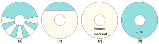
[41], the heat transfer rate increased by 49.3% and 10% during melting and solidification, respectively. Comprehensive numerical investigation of the LHTES with PCM locally enhanced with copper foam (
Figure 3) was conducted by Xu et al.
[43]. It was concluded that to achieve the lowest melting time simultaneously maintaining the heat storage capacity value of the LHTES system as high as possible (by reducing the mass of TCE), foam inserts should be gathered in the lower part of the annular region (
Figure 3a). Compared to a case in (
Figure 3d), the average heat transfer rate increased to 5.1, 6.8, and 6.9 times for cases (
Figure 3a), (
Figure 3b), and (
Figure 3c), respectively, but the heat storage capacity per unit mass decreased to 0.93, 0.86, and 0.81 times for cases (
Figure 3a), (
Figure 3b), and (
Figure 3c), respectively. Although the best thermal performance in terms of melting time and heat transfer rate was achieved by the LHTES unit filled with metal foam/PCM (
Figure 3c), the units with PCM locally enhanced (cases (
Figure 3a) and (
Figure 3b)) might reduce the costs of metal foam. This is consistent with the conclusion made by Gasia et al.
[44], who investigated four heat exchangers with: pure PCM, 17 aluminum fins, metallic wool distributed in a finned shape around the HTF tubes, and metallic wool distributed randomly around the HTF tubes. It was concluded that although the heat exchanger with fins gave the best performance, the advantage of metallic wool is its availability and low price. Lu et al.
[48] estimated that the cost of CPCM consisted of KNO
3-LiNO
3-Ca(NO
3)
2 and expanded graphite (EG) was lower than the pure PCM, because the price of EG was lower than the price of PCM. Nevertheless, a majority of researchers neglect the cost of CPCMs.
Figure 3. A cross-section of LHTES units with (
a) porous inserts, (
b) partially filled LHTES with metal foam, (
c) LHTES with PCM/metal foam composite, (
d) LHTES with PCM only
[43].
Phase change temperature is another important property of composite PCMs with inserts at micro/macro-scale, which defines their application suitability. Based on data in
Table 4, it can be concluded that in most cases the melting temperature of CPCMs decreases slightly, by less than 4 °C
[46][48][49][51][52][53][57][58], which is an acceptable change. Nevertheless, much more reduction of melting temperature, by 18 °C, was also observed
[50]. In some studies
[34][36][39][47][56] a slight increase, from 0.96 °C
[36] to 1.9 °C
[47], of the melting temperature was detected. Usually, the changes in melting temperatures were independent of the mass or volume fraction of additive. However, some researchers found that the changes in melting temperatures were proportional to the fraction of additives
[46], especially when the EG was used as TCE
[48][50][51]. Different types of MgO (light and heavy, with densities of 0.2 g/mL and 0.5 g/mL, respectively) were used by Li et al.
[59], who found that the melting temperature of CPCM with light and heavy MgO decreased by 3–5 °C and 6–9 °C, respectively, compared to pure PCM. Kenisarin et al.
[52] used two types of EG with different sizes: 200–1200 μm and 50–200 μm. The melting temperature of CPCMs with large EG size, and with small EG size decreased by 1 °C, and 7–8 °C, respectively, compared to pure PCM. According to Kenisarin et al.
[52], that difference was caused by some intermolecular interactions between PCM and the smaller EG. It should be noted, that only Kenisarin et al.
[52] discovered some intermolecular interactions between the PCM and the additive. According to the authors, the nature of these interactions should be further investigated. The vast majority of the research found that PCMs and additives are physically mixed and no chemical reactions occur among them
[25][28][34][35][36][37][38][39][40][42][43][47][49][51][54].
Another advantage of CPCMs is their reduced supercooling degree, compared to pure PCMs
[53][54][57][60]. For example, in research conducted by Xiao et al.
[54] the supercooling degree was reduced from 13 °C (pure PCM) to 2.4 °C (composite PCM). The supercooling degree of CPCMs prepared by Qu et al.
[56] was only 0.1 °C, but the researchers did not give the value of the supercooling degree for pure PCM. Fu et al.
[49] and Yuan et al.
[50] found that a larger reduction of supercooling degrees can be obtained by increasing the mass fraction of additive. On the other hand, Huang et al.
[34] showed that the supercooling degree increased from 0.51 °C for pure PCM, to 2.75–3.50 °C for CPCMs with copper, and nickel foam. A similar finding was obtained by Xiao et al.
[36].
The properties of CPCMs should not change after many melting-solidification cycles, which means that they should possess good cycling stability. Generally, after numerous melting/solidification cycles of the CPCMs listed in
Table 4, their latent heat decreased
[27][46][49][52][53][54][57][58][60] in the range from 0.7%
[46] to 19%
[52] after 200 phase change cycles. The changes in melting temperature were usually referred to as negligibly small
[46][49][52][53][54][60]. However, Xiao et al.
[54] found that the supercooling degree of CPCM increased after 400 melting-solidification cycles, but its value was still below 5 °C. Additionally, Li et al.
[58] found that after 25 cycles the weight loss of CPCM was less than 10%, which indicated leakage of the PCM. A small leakage, i.e., the CPCM’s mass decreased by 1.38%, of the PCM after 40 cycles was reported also by Yuan et al.
[50]. Furthermore, Li et al.
[59] observed a breakage of graphite flakes in the CPCM after 100 cycles.
Additives at micro/macro-scales should not impact the thermal stability of CPCMs, especially they should not reduce a decomposition temperature. Some studies confirmed that there were no noticeable changes in the decomposition temperature of CPCMs, compared to pure PCMs
[34][39][51][53][57][59][60]. For example, the decomposition temperature of CPCM prepared by Cheng et al.
[46] decreased by 2.9 °C, compared to pure PCM. It could be concluded, that such small change does not influence the working temperature range of CPCMs.
Adding materials at micro/macro-scale into PCMs has also an operational advantage. It can prevent PCMs from leakage due to the possibility of preparing shape-stable composite materials
[25][34][36][37][38][42][47][50][51][52][54][63]. Depending on the type of additive, different mass fractions of additives must be used to prevent PCM from leakage. Yuan et al.
[50], Zhang et al.
[53], and Zhu et al.
[27] prepared the erythritol/EG, n-eicosane/EG/SiO
2, and paraffin wax/expanded vermiculite composite materials, respectively, and the maximum mass fractions of PCMs in these composite materials were 90%, 70%, and 60%, respectively. If the mass fractions of PCMs in the CPCMs exceeded the abovementioned values, a leakage of PCMs occurred. Another interesting property that CPCMs might possess is flexibility, which was reported by Wu et al.
[51]. They prepared the flexible CPCM using paraffin wax, olefin block copolymer (OBC) and EG. Such flexible CPCM may considerably extend the scope of CPCMs use. On the other hand, the use of porous ceramics as TCE allowed preparing CPCMs with high mechanical strength
[58][59].
Summarizing, the application of additives at micro/micro-scales can provide many benefits. Firstly, it can significantly (up to 50 times) improve the thermal conductivity of PCMs, and as a result, shorten phase change time (up to 93.6%). However, some studies proved that the additives may suppress natural convection during melting and therefore extend phase change time. It should be noted that the phase change time was not always investigated by researchers. Moreover, the charging/discharging time was defined differently by different researchers, which makes it difficult to compare. Another advantage of CPCMs is that they provide more uniform temperature distribution in LHTES units, and they possess good thermal and cycling stability. Generally, melting temperatures of CPCMs are very similar to those of pure PCMs, while the supercooling degree of CPCMs might be reduced and reach value as low as 0.1 °C. Additionally, the additives can prevent PCMs from leakage. On the other hand, the main negative effect of using additives at micro/macro-scales is decreased latent heat of CPCMs (up to 83.5%). Hence, the heat storage density of a LHTES unit might be reduced. However, some studies showed that the heat storage density of a TES unit with CPCM might be higher compared to a unit with pure PCM, because of specific heat stored in the additive. The next important feature of CPCMs is their cost, which is overlooked by most of the researchers. Therefore, it can be generally concluded that there is a lack of studies that investigate every aspect of preparing CPCMs and all their most important properties.