An increasing number of practical applications (e.g. medical implants, embedded sensors in buildings and bridges, industrial applications) are based on the use of Wireless Sensor Nodes (WSNs), which are small computing devices capable of collecting and transmitting data to a base station. In order to limit or to avoid the drawbacks associated to the use of primary batteries (expensive maintenance/replacement, insufficient or unpredictable duration of operational life, not eco-friendly disposal due to their hazardous chemical content), the required energy can be delivered to the WSNs by energy harvesting. Energy harvesting is the conversion of otherwise wasted energy into electrical energy. Since vibrations can be found almost everywhere, an interesting possibility is represented by the use of vibration energy harvesters.
Here the attention is focused on Resonant Vibration Energy Harvesters (RVEHs) and in particular on Piezoelectric RVEHs and Electromagnetic RVEHs. A brief description of their operating principles is provided and their equivalent electric circuits are analyzed in order to identify the operating conditions able to maximize the extracted electrical power. This is a crucial aspect in applications involving energy harvesting systems. Moreover a brief introduction to the concepts of Electrical and Mechanical Tuning Techniques is also provided.
- vibration energy harvesters
- resonance frequency tuning
- maximum power extraction
- optimization
1. Introduction
Vibration energy harvesters are emerging devices that are able to scavenge otherwise wasted energy from ambient vibrations. In the last years, vibration harvesters have been proposed for a large number of applications, such as industrial applications, medical implants, embedded sensors in buildings and bridges, regenerative suspensions for automotive applications and regenerative backpacks for wearable applications [1],[2],[3],[4],[5],[6],[7]. In particular, in the future, vibration harvesters could be fundamental for the development of Internet of Things (IoT) applications and for Industry 4.0 revolution. In fact, IoT applications adopt wireless sensor networks made of many wireless sensor nodes (small computing devices that are able to collect and transmit data to a base station). The required energy can be delivered to the nodes of a wireless sensor network by means of vibration harvesters [2],[5]. In this way, the nodes can become self-sufficient from the energy point of view and therefore the drawbacks of disposable batteries (environmental risks, limited reliability, need for replacement) can be strongly limited. The number of publications per year focusing on vibration energy harvesters is illustrated in Figure 1 starting from 2005. Figure 1 demonstrates the increasing scientific interest of researchers on such a topic.
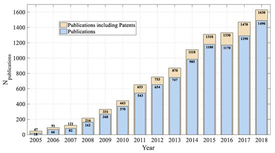
Figure 1. Publication profile regarding vibration energy harvesters (Source Google Scholar, Keyword Search: “Vibration Energy Harvesting”).
Here the attention is focused on Resonant Vibration Energy Harvesters (RVEHs) and on the maximization of their extracted electrical power, which, as it will be explained in the following, is of fundamental importance in practical applications [8],[9],[10][11].
2. Piezoelectric and Electromagnetic Resonant Vibration Energy Harvesters
2.1. Modeling and Maximum Power Extraction
RVEHs are devices capable of converting the mechanical energy associated to a vibration source into electrical energy. Such an energy conversion is based on a transduction mechanism that can fall in one of the following main categories: Piezoelectric [12],[13],[14], electromagnetic [15],[16],[17], electrostatic (including dielectric elastomers based) [18],[19],[20], magnetostrictive [21] and triboelectric [22]. Here the attention is focused on both Piezoelectric RVEHs (P-RVEHs) and Electromagnetic RVEHs (E-RVEHs), since they exhibit the highest values of power densities.
P-RVEHs are based on the piezoelectric effect that is the capability of given materials (e.g., crystals and some ceramics) to give rise to an electric voltage when subjected to a mechanical stress. In this way, they are able to lead to the conversion of mechanical energy into electrical energy.
In an E-RVEH, instead, a magnetic field is produced by a vibrating magnet and an electromotive force is induced in a coil fixed to the frame. Due to vibrations, a relative displacement occurs between the magnet and the coil leading to the conversion of mechanical energy into electrical energy.
The schematic models of P-RVEHs and E-RVEHs are shown in Figure 2.
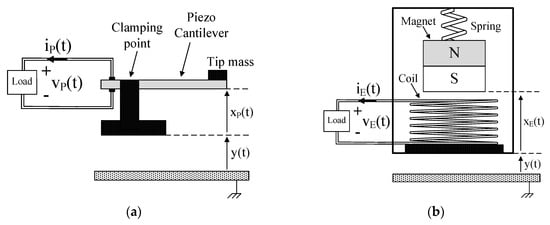
Figure 2. (a) Schematic model of a piezoelectric resonant vibration energy harvester (P-RVEH). (b) Schematic model of an electromagnetic (E-RVEH).
As shown in Figure 2a, in a P-RVEH a piezoelectric cantilever is clamped to a support to which vibrations are applied. The tip of the cantilever (where a mass is attached) moves out of phase with respect to the support. Therefore, there is a relative displacement xP(t) between the tip of the cantilever and the clamping point leading to the generation of electric energy. As shown in Figure 2b, in an E-RVEH a permanent magnet is connected to a spring and, due to vibrations, it moves out of phase with respect to the generator housing to which a coil is fixed. The relative displacement xE(t) taking place between the magnet and the coil gives rise to the conversion of mechanical energy into electric energy.
The devices of Figure 2 can be represented by means of the single degree of freedom (SDOF) systems represented in Figure 3 where the forces acting on the masses mP (which is a combination of the equivalent piezoelectric cantilever mass and of the tip mass [23]) and mE (oscillating magnet mass) are depicted by means of suitable arrows.
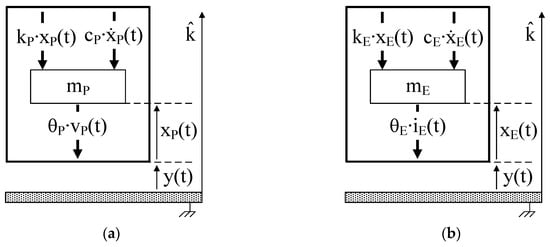
Figure 3. (a) Single degree of freedom (SDOF) model of a P-RVEH. (b) SDOF model of an E-RVEH.
In particular:
cP∙ẋP(t) and cE∙ẋE(t) are the viscous damping forces (cP and cE are the viscous damping coefficients).
kP∙xP(t) and kE∙xE(t) are the elastic forces (kP is the equivalent stiffness of the piezoelectric cantilever and kE is the equivalent stiffness of the spring).
θP∙vP(t) is the force due to the piezoelectric inverse effect that opposes to the strain of the piezoelectric material (θP is the piezoelectric electromechanical coupling coefficient).
θE∙iE(t) is the electromagnetic force that opposes to the movement of the magnet (θE is the electromechanical coupling coefficient of the coil).
The application of Newton’s second law, along the k-axis, to such SDOF systems leads to the following equations that rule the relative displacements xP(t) and xE(t) [24]
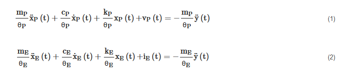
where ÿ(t) is the base acceleration. Since each addend of (1) is an electric voltage, it is possible to identify for P-RVEHs the loop based equivalent electric circuit enclosed in the dashed rectangle in Figure 4a. Since, instead, each addend of (2) is an electric current, it is possible to identify for E-RVEHs the node based equivalent electric circuit enclosed in the dashed rectangle in Figure 4b.
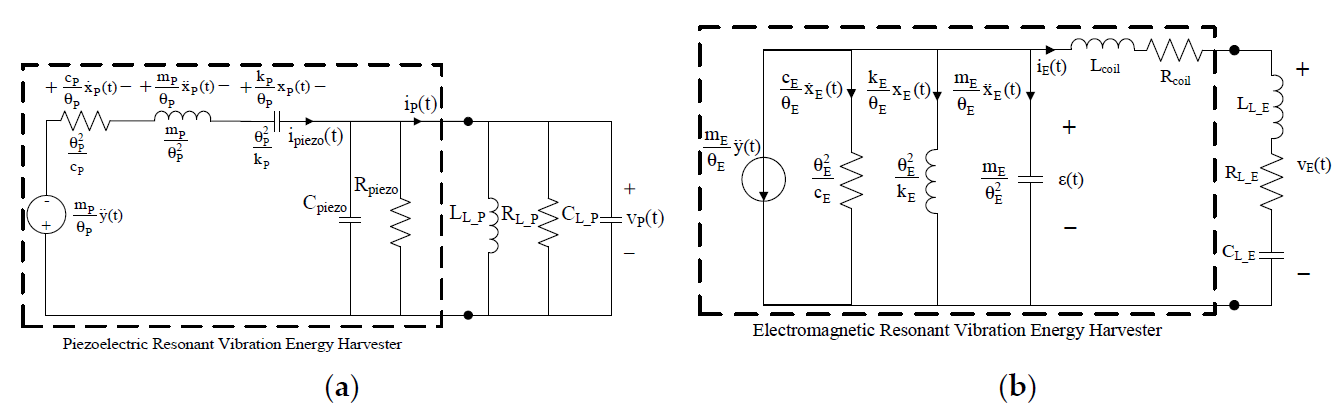
Figure 4. (a) Equivalent electric circuit of P-RVEHs. (b) Equivalent electric circuit of E-RVEH.
In Figure 4a, Cpiezo and Rpiezo, respectively are the capacitance and the resistance at the output of the piezoelectric layers. ipiezo(t) is the current generated by the piezoelectric effect whose expression is given in (3). The parallel of LL_P, RL_P, and CL_P represents a generic linear load that is connected to the P-RVEH and iP(t) and vP(t), respectively are the current and voltage across such a load.
In Figure 4b, Lcoil and Rcoil, respectively are the inductance and the resistance of the harvester coil. εcoil(t) is the electromotive force induced in the coil whose expression is given in (4). The series of LL_E, RL_E, and CL_E represents a generic linear load that is connected to the E-RVEH and iE(t) and vE(t), respectively are the current and voltage across this load.
It should be highlighted that the load parallel connection in Figure 4a and the load series connection in Figure 4b have been chosen, without any loss of generality, in order to get two completely dual systems.

If the acceleration ÿ(t) of the base vibration is sinusoidal with a frequency fvib and amplitude Avib (ÿ(t) = Avib∙cos(2πfvib∙t)), the Equations (1), (2), (3) and (4) can be written in the frequency domain and respectively become (5), (6), (7) and (8)
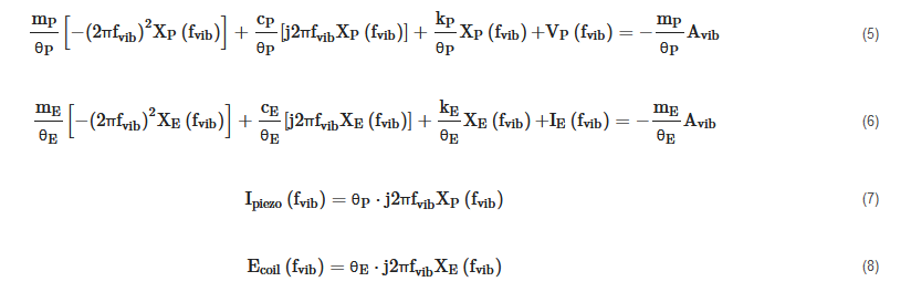
where XP(fvib), VP(fvib), XE(fvib), IE(fvib), Ipiezo(fvib), and Ecoil(fvib), respectively are the Fourier transforms of xP(t), vP(t), xE(t), iE(t), ipiezo(t), and εcoil(t). j is the imaginary unit.
By analyzing the circuits of Figure 4a,b it is possible to write
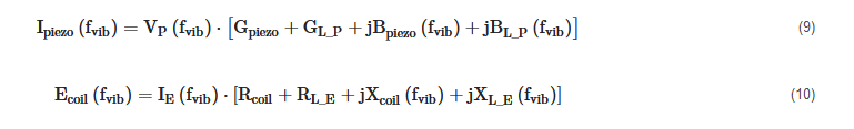
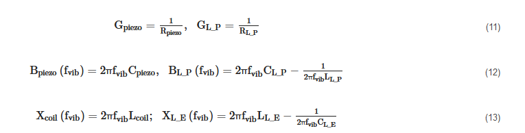
where Gpiezo = 1/Rpiezo, GL_P = 1/RL_P
From (7), (8), (9) and (10) the following expressions of the relative displacements XP(fvib) and XE(fvib) can be obtained
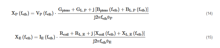
Therefore, by putting (14) and (15), respectively in (5) and (6), we get
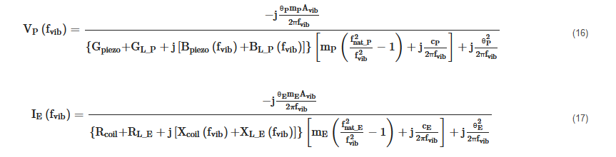
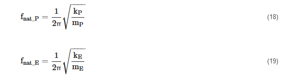
Where fnat_P and fnat_E are the undamped natural frequencies of the SDOF systems shown in Figure 3.
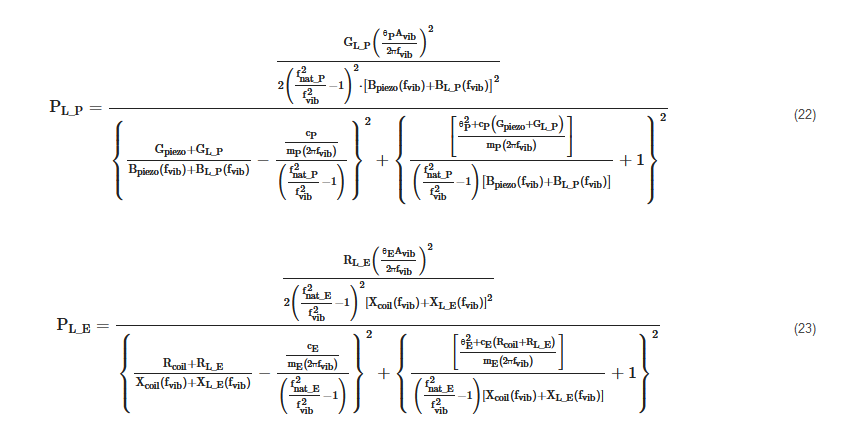
Finally, the powers transferred from the two types of RVEHs to their loads are
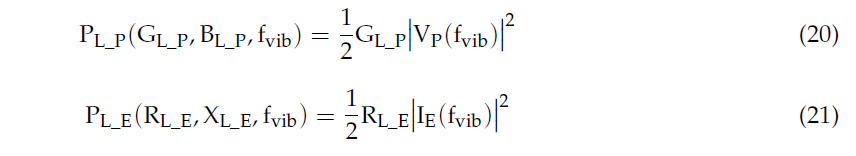
As it is evident from (20) and (21), the powers depend on the frequency of the base acceleration and on the connected loads. Their expressions are provided in (22) and (23).
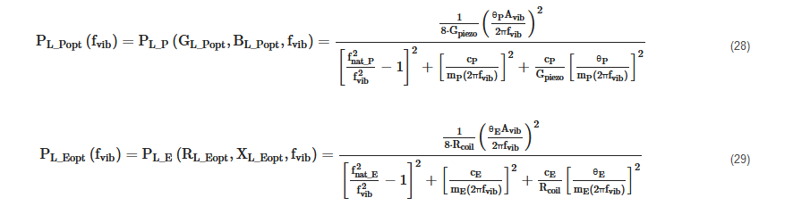
The optimal loads, that maximize the two powers PL_P(GL_P,BL_P,fvib) and PL_E(RL_E,XL_E,fvib) at a given frequency, are:

The maximum powers PL_Popt(fvib) and PL_Eopt(fvib) provided to the optimal loads, at a given frequency, can be obtained by substituting expressions (24) and (26) in (22) and (25) and (27) in (23):
In Figure 5, the typical trend that is exhibited by the maximum load powers of a P-RVEH and of an E-RVEH vs. the vibration frequency (fvib) is reported. The unique symbol PLopt is used in Figure 5 for the maximum load power of both types of RVEHs.
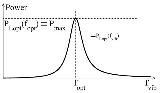
Figure 5. Typical shape of the power extracted by a RVEH (P-RVEH or E-RVEH), when loaded with the optimal impedance as a function of the vibration frequency.
It is clear that, due to the resonant nature of RVEHs, the global maximum power (the peak power Pmax in Figure 5) is provided to the optimal loads only when the vibration frequency is equal to the frequencies fPopt and fEopt (a unique symbol fopt is used in Figure 5). By differentiating (28) and (29) with respect to fvib and by equating to zero the obtained expressions it is possible to find the values of the frequencies fPopt and fEopt.
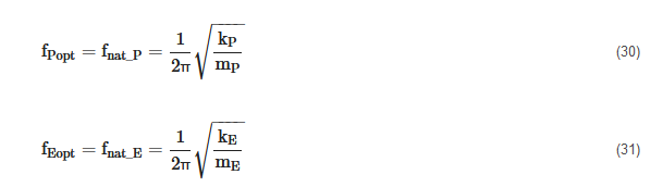
As shown in (30) and (31), fPopt and fEopt are coincident with the undamped natural frequencies of the SDOF RVEHs’ models and are typically also called mechanical resonance frequencies. It is worth noting here that, by observing the equivalent circuits of Figure 4, the above mechanical resonance frequencies can be obtained by means of suitable frequency scans of proper electrical quantities at the output of the RVEHs. In particular, in the case of P-RVEHs, the fPopt is equal to the resonance frequency of the short circuit current. Instead, in the case of E-RVEHs, fEopt is equal to the resonance frequency of the open circuit voltage.
The expressions of the global maximum powers provided by the RVEHs in correspondence of their mechanical resonance frequencies are reported in (32) and (33).
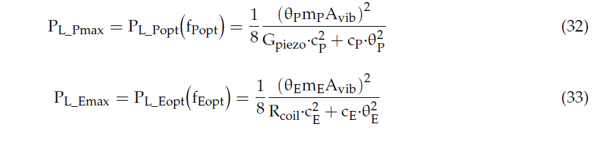
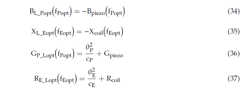
It is worth highlighting that, in correspondence of the mechanical resonance frequencies fPopt and fEopt of the RVEHs, the optimal loads assume simplified expressions:
2.2. Definition of Tuning Techniques
Due to their resonant nature, RVEHs are able to efficiently operate only when the vibrations’ frequency is equal to their mechanical resonance frequency (see Figure 5). This means that, once a given RVEH has been factory tuned to a predefined mechanical resonance frequency (fopt), it has to be used only in those applications that are characterized by a dominant frequency (fvib) that is coincident with such a mechanical resonance frequency. During the last years, some papers have been proposed in the scientific literature on the optimal design of RVEHs based on the characteristics of the vibrations [25]. As an example, cantilever beam shape optimization has been studied in great detail in case of P-RVEHs. Unfortunately, in most practical cases, the frequencies of the exploitable sinusoidal vibrations are time-varying or even such vibrations are not sinusoidal but are characterized by a random behavior with a wide frequency spectrum where the energy is distributed [26]. Therefore, in practical applications, the increase of the effective operating frequency range of RVEHs is mandatory. In the literature, a number of papers describing control methods or architectures that are specifically designed with the aim of increasing the effective operating frequency range of RVEHs, has been proposed [24],[27],[28]. In particular, harvesters arrays, nonlinear harvesters, and mechanical tuning techniques (MTTs) are the most widely analyzed optimization methods. There is general agreement on the fact that MTTs are much more promising with respect to the other two options. This is essentially due to the low volumetric power density of harvesters arrays and to the considerable complexity of nonlinear harvesters [29].
MTTs of RVEHs are essentially based on the proper regulation of their mechanical resonance frequency in order to make it (theoretically) always coincident with the vibration frequency (the objective is to obtain fopt = fvib in all the operating conditions). Obviously, as it is evident from the previous Modeling Section, another requirement is mandatory for maximizing the extraction of power from RVEHs. In fact, even if the mechanical resonance frequency of a RVEH is always coincident with the vibration frequency, the extracted power is dependent on the RVEH load impedance. In particular, according to Section 2.1 (see Equations from (24) to (27) and from (34) to (37)) and on the basis of the maximum power transfer theorem [30], the optimal load impedance of a RVEH, that is the load impedance able to maximize power drawn from the RVEH itself, changes with fvib. Therefore, a second objective to fulfill is the matching of the RVEH with its optimal load impedance, frequency by frequency. This is the aim of the so-called electrical tuning techniques (ETTs) [31],[32],[33]. It is worth noting that the application of the ETTs of course does not change the mechanical resonance frequency of a RVEH. ETTs allow the maximization of the extraction of power at each frequency; but the vibration frequency that allows to obtain the global maximum power (PMAX) always is the mechanical resonance frequency. The only way to change such a frequency is by means of a MTT. In order to better clarify such a statement, it is useful to analyze the following figures.
In Figure 6a the application of ETTs is explained. In particular, each color curve represents the frequency scan of the power PL(RLopt(fk),XLopt(fk),fvib) provided to the fixed load (RLopt(fk),XLopt(fk)) (k = 1, 2,… n). Each color curve PL(RLopt(fk),XLopt(fk),fvib) has been obtained in correspondence of a different fixed load (RLopt(fk),XLopt(fk)) that is just the optimal load in correspondence of the frequency fk (see Equations from (24) to (27)). Therefore, each color curve is maximized only when fvib = fk. The envelope of the maximums PETT(fvib) ≡ PLopt(fvib) ≡ PL(RLopt(fvib),XLopt(fvib),fvib) of the color curves (dashed black curve in Figure 6a) represents the maximum power, as a function of the frequency, that can be gotten with the application of the ETT. It is clear that the frequency that allows to obtain the maximum global harvesting of power is unique and coincident with the mechanical resonance frequency fopt. In conclusion, ETTs allow only the maximization of the extraction of power at a given vibration frequency fvib from a given RVEH with a fixed mechanical resonance frequency fopt. ETTs do not change the mechanical resonance frequency of the RVEH. As stated above, the only way to change such a frequency is by means of a MTT. In other words, the black dashed curve PETT(fvib) of Figure 6a indicates the best performance that can be obtained with the application of only ETT without MTT.
In Figure 6b the application of MTT is explained. In particular, the color curves have been obtained by using a fixed load that is without adopting any ETT. Such a fixed load is the optimal load (given by Equations from (34) to (37)) in correspondence of the RVEH untuned mechanical resonance frequency fopt (gray curve). What changes among the color curves is the mechanical resonance frequency fopt_k (k = 1, 2,…n). In other words, the color curves represent a sort of horizontal translation, at different resonance frequencies, of the central grey curve of Figure 6b that coincides with the central gray curve of Figure 6a. The envelope of the maximums of such color curves (dashed black curve in Figure 6b) represents the maximum power PMTT(fvib) ≡ PL(RLopt(fopt),XLopt(fopt),fvib) that can be harvested, as a function of the frequency, by applying MTT without ETT. It is clear that, in this case, the performance of the RVEH is improved, with respect to the case of Figure 6a, because the mechanical characteristics of RVEH are changed and therefore it always resonates in correspondence of the vibration frequency fvib. However, by observing the dashed black curve in Figure 6b, it is evident that there is still an optimal frequency. It is the untuned resonance frequency fopt. This happens because a fixed load has been considered and such a load is just the optimal one at fopt. This aspect can be clarified by observing that the optimal load at fopt (see Equations from (34) to (37)) has a resistive part that is independent from the resonance frequency and hence it does not need a regulation while applying MTT. Instead, the reactive part of the optimal load at fopt, that compensates the reactive part of the output impedance of the considered RVEH (Cpiezo for P-RVEH and Lcoil for E-RVEH), depends on the frequency and hence it would need a regulation while applying MTT. Therefore, a fixed not optimized load, leads to the nonhorizontal shape of the maximum extracted power PMTT(fvib) (black dashed curve in Figure 6b).
Taking into account the previous considerations it is clear that, in general, for the optimal exploitation of a RVEH it is necessary to apply jointly both a MTT and an ETT at the same time as shown in Figure 6c. In this case, as desired, the perfect horizontal translation of the maximum extractable power curve is obtained. In other words, the color curves in Figure 6c represent perfect horizontal translations, at different resonance frequencies, of the black dashed curve of Figure 6a. The envelope of the maximums of such color curves (dashed black curve in Figure 6c) represents the maximum power PMTT-ETT(fvib) ≡ Pmax ≡ PL(RLopt(fvib),XLopt(fvib),fvib) that can be extracted, frequency by frequency, with the joint application of both a MTT and an ETT.
Summarizing, the application of an ETT without any MTT leads to the extraction of the power PETT(fvib) represented by the black dashed curve in Figure 6a. The application of a MTT without any ETT leads to the extraction of the power PMTT(fvib) represented by the black dashed curve in Figure 6b. The joint application of both an ETT and a MTT leads to the extraction of the power PMTT-ETT(fvib) represented by the black dashed curve in Figure 6c.
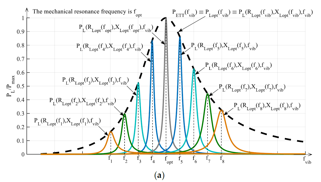
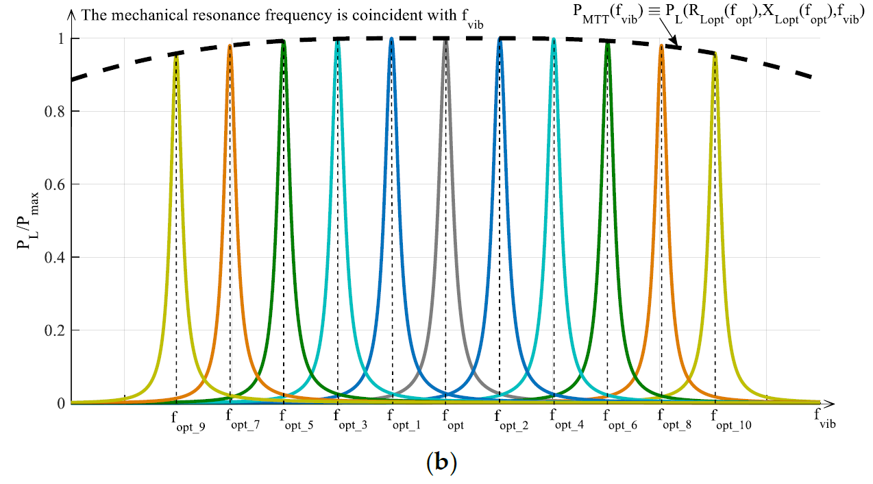
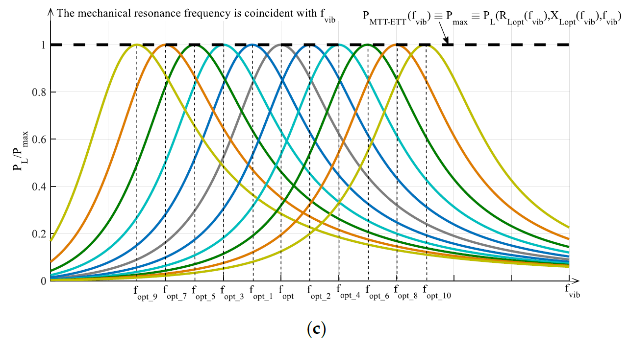
Figure 6. Typical trends vs. the normalized vibration frequency of the powers provided to the load by a RVEH (P-RVEH or E-RVEH) with the application of: (a) ETT, (b) MTT, (c) both ETT and MTT.
This entry is adapted from the peer-reviewed paper 10.3390/en13030527
References
- Jee Siang; M.H. Lim; M. Salman Leong; Review of vibration-based energy harvesting technology: Mechanism and architectural approach. International Journal of Energy Research 2018, 42, 1866-1893, 10.1002/er.3986.
- Marco Balato; Luigi Costanzo; Massimo Vitelli; MPPT in Wireless Sensor Nodes Supply Systems Based on Electromagnetic Vibration Harvesters for Freight Wagons Applications. IEEE Transactions on Industrial Electronics 2016, 64, 3576-3586, 10.1109/tie.2016.2644605.
- Luigi Costanzo; Teng Lin; Weihan Lin; Alessandro Lo Schiavo; Massimo Vitelli; Lei Zuo; Power Electronic Interface With an Adaptive MPPT Technique for Train Suspension Energy Harvesters. IEEE Transactions on Industrial Electronics 2020, 68, 8219-8230, 10.1109/tie.2020.3009584.
- Luigi Costanzo; Mingyi Liu; Alessandro Lo Schiavo; Massimo Vitelli; Lei Zuo; Backpack energy harvesting system with maximum power point tracking capability. IEEE Transactions on Industrial Electronics 2021, PP, 1-1, 10.1109/tie.2021.3053896.
- Osvaldo Brignole; Claudio Cavalletti; Antonino Maresca; Nadia Mazzino; Marco Balato; Antonio Buonomo; Luigi Costanzo; Massimiliano Giorgio; Roberto Langella; Alessandro Lo Schiavo; et al. Resonant electromagnetic vibration harvesters feeding sensor nodes for real-time diagnostics and monitoring in railway vehicles for goods transportation: A numerical-experimental analysis. 2016 IEEE International Power Electronics and Motion Control Conference (PEMC) 2016, vol, 456-461, 10.1109/epepemc.2016.7752040.
- Luigi Costanzo; Massimo Vitelli; Yu Pan; Lei Zuo; Maximizing the Power Extraction From Train Suspension Energy Harvesting System. Volume 8: 31st Conference on Mechanical Vibration and Noise 2019, vol, pp, 10.1115/detc2019-98209.
- Luigi Costanzo; Massimo Vitelli; Alessandro Lo Schiavo; Lei Zuo; Optimization of diode bridge rectifier output voltage in Train Suspension Energy Harvesters. 2020 IEEE 20th Mediterranean Electrotechnical Conference ( MELECON) 2020, vol, 197-201, 10.1109/melecon48756.2020.9140723.
- Marco Balato; Luigi Costanzo; Massimo Vitelli; Maximization of the extracted power in resonant electromagnetic vibration harvesters applications employing bridge rectifiers. Sensors and Actuators A: Physical 2017, 263, 63-75, 10.1016/j.sna.2017.04.002.
- Luigi Costanzo; Alessandro Lo Schiavo; Massimo Vitelli; Power maximization from resonant electromagnetic vibration harvesters feeding bridge rectifiers. International Journal of Circuit Theory and Applications 2018, 47, 87-102, 10.1002/cta.2574.
- Luigi Costanzo; Massimo Vitelli; The ideal utilization factor: A tool to optimize the energetic performances of resonant electromagnetic vibration energy harvesters. 2018 Thirteenth International Conference on Ecological Vehicles and Renewable Energies (EVER) 2018, vol, 1-7, 10.1109/ever.2018.8362383.
- Luigi Costanzo; Massimo Vitelli; Maximum Power Transfer in Electromagnetic Vibration Energy Harvesters driven by Non-Sinusoidal Vibrations. 2019 International Conference on Clean Electrical Power (ICCEP) 2019, vol, 235-241, 10.1109/iccep.2019.8890078.
- Hassan Elahi; Marco Eugeni; Paolo Gaudenzi; A Review on Mechanisms for Piezoelectric-Based Energy Harvesters. Energies 2018, 11, 1850, 10.3390/en11071850.
- Luigi Costanzo; Alessandro Lo Schiavo; Massimo Vitelli; Power Extracted From Piezoelectric Harvesters Driven by Non-Sinusoidal Vibrations. IEEE Transactions on Circuits and Systems I: Regular Papers 2018, 66, 1291-1303, 10.1109/tcsi.2018.2879751.
- Luigi Costanzo; Alessandro Lo Schiavo; Alessandro Sarracino; Massimo Vitelli; Stochastic Thermodynamics of a Piezoelectric Energy Harvester Model. Entropy 2021, 23, 677, 10.3390/e23060677.
- Yushan Tan; Ying Dong; Xiaohao Wang; Review of MEMS Electromagnetic Vibration Energy Harvester. Journal of Microelectromechanical Systems 2016, 26, 1-16, 10.1109/jmems.2016.2611677.
- Marco Balato; Luigi Costanzo; Massimo Vitelli; Resonant electromagnetic vibration harvesters: Determination of the equivalent electric circuit parameters and simplified closed-form analysis for the identification of the optimal diode bridge rectifier DC load. International Journal of Electrical Power & Energy Systems 2017, 84, 111-123, 10.1016/j.ijepes.2016.05.004.
- Marco Balato; Luigi Costanzo; Massimo Vitelli; Identification of the parameters of the equivalent electric circuit of electromagnetic harvesters. 2015 International Conference on Renewable Energy Research and Applications (ICRERA) 2015, vol, 1641-1645, 10.1109/icrera.2015.7418684.
- Yasuyuki Naito; Keisuke Uenishi; Electrostatic MEMS Vibration Energy Harvesters inside of Tire Treads. Sensors 2019, 19, 890, 10.3390/s19040890.
- Marco Balato; Luigi Costanzo; Massimo Vitelli; Closed-form analysis of Switchless Electrostatic Vibration Energy Harvesters. 2015 Tenth International Conference on Ecological Vehicles and Renewable Energies (EVER) 2015, vol, 1-7, 10.1109/ever.2015.7112921.
- Gordon Thomson; Daniil Yurchenko; Dimitri V. Val; Zhien Zhang; Predicting energy output of a stochastic nonlinear dielectric elastomer generator. Energy Conversion and Management 2019, 196, 1445-1452, 10.1016/j.enconman.2019.06.055.
- Gary Backman; Ben Lawton; Nicola A. Morley; Magnetostrictive Energy Harvesting: Materials and Design Study. IEEE Transactions on Magnetics 2019, 55, 1-6, 10.1109/tmag.2019.2891118.
- Zhong Lin Wang; Tao Jiang; Liang Xu; Toward the blue energy dream by triboelectric nanogenerator networks. Nano Energy 2017, 39, 9-23, 10.1016/j.nanoen.2017.06.035.
- Waleed Al-Ashtari; Matthias Hunstig; Tobias Hemsel; Walter Sextro; Analytical determination of characteristic frequencies and equivalent circuit parameters of a piezoelectric bimorph. Journal of Intelligent Material Systems and Structures 2011, 23, 15-23, 10.1177/1045389x11430742.
- Luigi Costanzo; Massimo Vitelli; Tuning Techniques for Piezoelectric and Electromagnetic Vibration Energy Harvesters. Energies 2020, 13, 527, 10.3390/en13030527.
- Lokesh Dhakar; Huicong Liu; F.E.H. Tay; Chengkuo Lee; A new energy harvester design for high power output at low frequencies. Sensors and Actuators A: Physical 2013, 199, 344-352, 10.1016/j.sna.2013.06.009.
- Luigi Costanzo; Alessandro Lo Schiavo; Massimo Vitelli; Modeling Piezoelectric Harvesters under Amplitude and Frequency Modulated Vibrations. 2019 26th IEEE International Conference on Electronics, Circuits and Systems (ICECS) 2019, vol, 915-918, 10.1109/icecs46596.2019.8964969.
- Title: Vibration energy harvester, optimized by electronically emulated mechanical tuning technique, inventors: M. Balato, L. Costanzo, A. Lo Schiavo, M. Vitelli. Submission number 7288000, PCT application number PCT/EP2019/056601, as extension of IT102018000003632.International Publication Number: WO2019/175413A1, https://patents.google.com/patent/WO2019175413A1/en.
- Title: Electronic device and method for the maximization of the mean power extracted from a vibrational harvester. Inventors: L. Costanzo, A. Lo Schiavo, M. Vitelli, International application number PCT/IB2020/052514, as extension of IT102019000004067.International Publication Number: WO2020/188511, https://patents.google.com/patent/WO2020188511A1.
- Kazmierski, T.J.; Beeby, S.. Energy Harvesting Systems; Springer: Berliv, 2014; pp. pp.
- C. S. Kong; A general maximum power transfer theorem. IEEE Transactions on Education 1995, 38, 296-298, 10.1109/13.406510.
- Marco Balato; Luigi Costanzo; Alessandro Lo Schiavo; Massimo Vitelli; Optimization of both Perturb & Observe and Open Circuit Voltage MPPT Techniques for Resonant Piezoelectric Vibration Harvesters feeding bridge rectifiers. Sensors and Actuators A: Physical 2018, 278, 85-97, 10.1016/j.sna.2018.05.017.
- Luigi Costanzo; Alessandro Lo Schiavo; Massimo Vitelli; Design Guidelines for the Perturb and Observe Technique for Electromagnetic Vibration Energy Harvesters Feeding Bridge Rectifiers. IEEE Transactions on Industry Applications 2019, 55, 5089-5098, 10.1109/tia.2019.2923162.
- Luigi Costanzo; Alessandro Lo Schiavo; Massimo Vitelli; Active Interface for Piezoelectric Harvesters Based on Multi-Variable Maximum Power Point Tracking. IEEE Transactions on Circuits and Systems I: Regular Papers 2020, 67, 2503-2515, 10.1109/tcsi.2020.2977495.