Your browser does not fully support modern features. Please upgrade for a smoother experience.
Please note this is an old version of this entry, which may differ significantly from the current revision.
Subjects:
Materials Science, Coatings & Films
Based on the recent analysis of various databases, cold spray (CS), the newest method among thermal spraying technologies, has received the unabated attention of hundreds of researchers continuously since its invention in the 1980s. The significance of CS lies in the low process temperature, which usually ensures compressive residual stresses and allows for the formation of coatings on a thermally sensitive substrate.
- low-pressure cold spraying
- ceramic coatings
- multi-functional coatings
- deposition efficiency
- powders preparation methods
Note: The entry will be online only after author check and submit it.
1. Introduction
Cold gas dynamic spraying, also known as kinetic spraying or simply cold spraying (CS), was originally developed in the mid-1980s as a coating deposition process by A. Papyrin and his team at the Institute of Theoretical and Applied Mechanics of the Russian Academy of Sciences in Novosibirsk [1]. Russian researchers reported several patents, including [2,3,4], and then published the first manuscript on CS in 1990 [5]. This invention was outstanding in the field of thermal spray technologies as the process enabled the deposition of solid-state metal particles. While improving the CS process, Papyrin’s team successfully deposited a wide range of pure metals, metal alloys, and metal–ceramic composites on a variety of substrate materials and demonstrated the feasibility of cold spraying for various applications. To safeguard this innovative technology in other continents, a U.S. patent on CS was issued in 1994 [6], and a European one in 1995 [7]. Until now researchers all over the world have been developing the CS process and widening its applications.
CS compared to other thermal spraying techniques is characterized as a low-temperature process [8,9]. Thermal energy necessary for powder deposition is replaced in CS by kinetic energy. The working gas gains supersonic velocity in the de Laval nozzle and, due to drag force, accelerates the powder particles. The velocity can be controlled by the pressure and temperature of the gas. In addition, the process temperature increases the plasticity of the metal particles, enabling mechanical bonding. Nevertheless, the melting point of the applied powder material is not exceeded and thus the particles are sprayed in the solid state. Low thermal energy generates many benefits, such as: (i) high coating purity with low porosity or oxidation level [10,11], (ii) controlled phase transformation [12,13], (iii) uniform microstructure without grain growth [14,15], (iv) possibility of coating of thermally sensitive substrates, e.g., polymers or aluminium moulds [4], as well as (v) relatively low and mostly compressive residual stresses resulting from the tamping effect of impinging solid particles [3].
Several parameters are influencing the CS process, including, powder and substrate material, particle morphology, oxidation level and spraying temperature, which decide about the coating formation and deposition efficiency as well [8,9,16]. However, a key parameter is the velocity of the particles resulting from the geometry of the spray gun nozzle, the type of working gas, and its temperature and pressure [17,18,19]. Therefore, the particles have to exceed the so-called critical velocity for a successful deposition. With velocities lower than a critical one, particles will abrade the substrate and rebound. Starting with the critical limit, which depends on the process parameters, particle adhesion to the substrate occurs. However, when the velocity is too high, the particles will provide strong erosion of the substrate [19,20,21,22,23,24,25,26]. High-pressure cold spraying (HPCS), as a more advanced method with high performance, is suitable for various ranges of metals. Simultaneously, it is stated that the application of low-pressure cold spraying (LPCS) compared to HPCS is significantly limited to easy-plastic-deformable materials such as tin, zinc, copper, aluminium, and nickel. The presented division results from process parameters and can be extended in the case of LPCS by proper powder modifications, e.g., ceramic to metal powder addition, two or more metal powder mixtures [27,28,29].
It is worth emphasising that CS was initially developed for spraying ductile metal powders due to the necessity of plastic deformation upon solid particles impact on the substrate. Therefore, mainly metals and various mixtures of metals and metal with ceramics were applied as feedstock powders [1,10]. The basic function of ceramic powder is to improve the mechanical and physical properties of the coating. The incoming hard particles cause peening and additional work hardening of metal particles, and thus coating densification, reinforcement, and grain refinement [30,31]. Parts of ceramics are crushed and wedged mechanically or interlocked by the soft matrix providing dispersion strengthening [32]. As a result, CS composite coating microstructures are composed of a highly deformed matrix and non-deformed reinforcement. Simultaneously, ceramic powder supports the deposition process by the following: (i) eliminating the nozzle clogging in spray gun models without water cooling [28,33,34], (ii) activation of the surface by removing the oxide layer and contamination [35,36,37], and (iii) roughening the surface increasing contact area [37,38]. On the other hand, the application of pure ceramic powder in CS usually requires a “soft” matrix. According to the latest research results, the proper preparation of ceramic powders ensures successful deposition. The mechanism based on plastic deformation can occur in ceramics. However, fine particles must be applied [39,40]. What is more, the velocity of nanosized ceramic powder can be increased by particle agglomeration. Appropriate powder production methods, e.g., spray drying or sol-gel, provide residues of organic additives, which work as a binder. Finally, nanosized agglomerated particles due to fragmentation will bond to the substrate.
Except for low process energy, typical advantages of the CS process include also high deposition efficiency, in situ micro-grit blasting, flexible substrate-coating materials combination and low process costs [41,42]. Moreover, deposited coatings are usually characterized by high density and wide thickness range, as well as improved electrical and thermal conductivity, corrosion resistance, strength, and hardness [41,43,44]. On the other hand, the main disadvantages that must be challenged include low toughness [41,45], ductility [46,47], and cohesion [48,49]. As a result, some applications may require post-spraying heat treatment (PSHT) [47,50]. A great opportunity for further development of the CS is the fabrication of nanostructured MMC and ceramic coatings. An optimized nanocrystalline powder material and the parameters of the spraying process provide many benefits, such as simultaneously high mechanical properties and high toughness [51,52], superior thermal and electrical properties [53], excellent transparency [50], or improved photocatalytic efficiency [54]. These improvements can be achieved in CS coatings by tailoring the composition and microstructure of the composite or ceramic powder. However, the control of nanostructures in the coating via powder preparation and processing parameters remains a challenging issue.
2. Metal Matrix Composite Coatings
Particle reinforced metal matrix composite (PRMMC) coatings consist of a ductile matrix (pure metal or metal alloy) and hard reinforcement phase (different metal, ceramics, intermetallic phase, organic or inorganic material), and as a result, combine properties of both materials, e.g., resistance for high-temperature mechanical loading, maintaining increased durability [77,78]. Due to high strength, hardness, chemical inertness, high melting point, and many functional applications, ceramic powder is the most commonly selected material for reinforcement in PRMMC coatings [77,79,80,81,82]. The uniformly distributed, coherent, and continuous hard phase in the metallic matrix increases the following properties of the coating: (i) mechanical properties, such as strength, elastic modulus, hardness, and wear resistance [81,83,84], (ii) chemical properties, including corrosion resistance [62,82,83], and (iii) physical properties, e.g., high-temperature stability [79,85], or electrical and thermal conductivity [62,86,87,88]. Among other thermal spraying techniques, CS ensures a solid state of PRMMC coatings deposition, without tensile thermal stresses, phase transformation, decarburization, oxidation, or high porosity [28,48,89,90]. The low cost of commercially available powder mixtures and easy control of coating composition makes PRMMC coatings an attractive alternative for complex alloys.
Metal particles in CS impact the substrate with high kinetic energy and as a result undergo severe plastic deformation at a high strain rate [18,61]. Strong pressure waves interact with the expanding edge of the particle forming a jet, which is prone to localized fragmentation under a spall-like process [91]. Additionally, the temperature may increase locally in the particle boundary region and cause adiabatic shear instability [61,92]. Despite the low temperature of the process, the flow of metal and jet formation occurs. This phenomenon favours the adhesion and cohesion of the particles. What is more, the deformation is increased in PRMMC by the tamping effect of hard ceramic particles. Therefore, despite lower particles velocities obtained in LPCS, ceramic powder ensures additional work hardening of the metal particles and significantly increases the mechanical properties of the PRMMC coating.
2.1. Powders Preparation
In the CS process, PRMMC coatings are deposited as a mixture of two or more metal–ceramic powders. The powders mixture can be prepared by several methods illustrated in Figure 5, such as: (i) mechanical blending of powders, offering simple operation and easy control over the composition of the composite powder [82,93,94], (ii) satelliting, to improve dispersion of the small reinforcing particles by the formation of satellites on the surface of large particle of second phase [95,96], (iii) powder cladding to form a continuous and uniform metal coating on the ceramic powder and increase control of the volume fractions of the hard phase [68], (iv) mechanical ball milling to improve the distribution of reinforcement phases with control of size and content of mixed phases [97,98], (v) ball milling combined with self-propagating high-temperature synthesis or annealing in controlled atmosphere to obtain a modified structure, and (vi) spray drying to facilitate the atomisation of slurry followed by drying in hot gas, agglomeration, and sintering, which ensures homogeneous, agglomerated composite powders [99,100]. Selecting a proper mixture preparation method should be matched with matrix phase and reinforcement phase, and most importantly with mixture application. In thermal spraying processes, various powders can react differently, e.g., high temperature causes decarburization, high plastic deformation leads to a decrease of DE, etc. All the methods are compared in Figure 1 and are precisely described below.
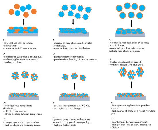
Figure 1. Comparison of different powder preparation methods and schematic deposition onto the substrate: mechanical blend (upper left), satelliting (upper middle), powder cladding (upper right), mechanical ball milling (lower left), ball milling with SHS or annealing (lower middle) and spray drying (lower right). Blue and orange colours mean various phases. A—advantage, D—disadvantage (inspired by [98]).
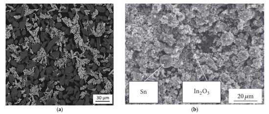
The blending of powders is the simplest and cheapest way to prepare the mixture and various materials with a high range of particles sizes that can be used in the process. Many commercially available powders for LPCS are prepared this way, including Al-Al2O3 [48,93,101], Cu-Al2O3 [62,102,103] (Figure 2), Zn-Al2O3 [81,102,104], Sn-Al2O3 [81,105,106], Ni-Al2O3 [68,81,102], and other powder mixtures for special application, such as Cu-SiC [82,107], Al2319-TiN [108], and WC-Ni [80]. Due to their higher kinetic energy, blended powders are effectively deposited by HPCS, e.g., Al-Al2O3 [109], aluminium alloys: A380-Al2O3 [110,111], AA2024-Al2O3 [112], Al5056-SiC [113], Cu-CuO2 [114], and Ni-B4C [115]. It should be emphasised that increasing differences in the particle size, morphology, or density of mixed powders result in various ranges of particles velocities. As a result, mixed materials show divergence in DE and, in consequence, nonuniform material distribution in the deposited coating [116]. What is more, particles size range should be above 5 µm, as smaller particles decelerate in the bow shock formed above the substrate [98]. Therefore, another method was proposed, known as satelliting. In this process, two powders with various particles sizes are mixed in liquid binder [95] or low-energy vibration mill [117,118] (Figure 2). As a result, small particles of the first phase form satellites on the surface of the second phase particles due to the action of van der Waals force. However, such a weak adhesion causes easy separation during satellite impact and usually some part of reinforcement rebounds. Al-Hamdani et al. [119] mixed Al powder (15–45 µm size range) and TiC powder (particle size < 5 µm) in a tubular mixer with the addition of a binder. Afterwards, the powder was dried at 100 °C for 12 h. Al-Hamdani et al. noticed the more evenly distributed TiC in the satellited feedstock, and subsequent more steady flow during spraying, compared to blended powders. As a result, a high proportion of ceramic that was attached to the satellited powder was embedded in the coating.
Powder cladding can be used to increase the amount of ceramic in the coating. Within the process, the selected metal is coated on a hard phase with defined thickness to obtain a desired fraction of ceramic material [68,120]. The method is dedicated to manufacturing cladded powders and mainly includes [68]: (i) immersion coating; (ii) electroless chemical plating; (iii) electrolytic deposition; (iv) mechanical coating; (v) chemical vapor deposition (CVD); (vi) physical vapor deposition; and (vii) hydrothermal hydrogen reduction method. By selecting the appropriate process and its optimal parameters, the thickness of the coated layer can be regulated. Deposited metal works as a binder and joins particles of hard phase to agglomerates [120] (Figure 3). The process enables the deposition of a coating with a high and controlled volume fraction of the hard phase. However, CS requires a metal matrix to spray any hard particles, including ceramics. Therefore, the thickness of the clad layer should be sufficient to ensure particle adhesion [68]. It should be noted that the reinforcing phase can be cladded on the metal particles. Okimura et al. [121], to increase hard phase in the LPCS coatings, proposed the deposition of diamond-like carbon (DLC) films on the surface of Ti and Cu powders by (CVD). Meanwhile, Wang et al. [122] encapsulated aluminium powder particles with graphene to increase the corrosion resistance of the coating.
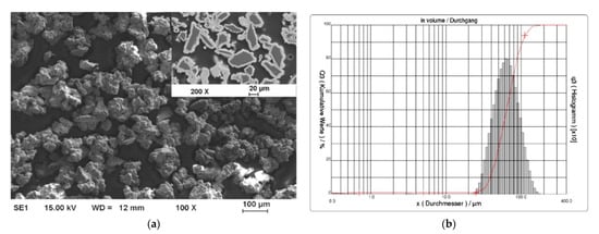
Figure 3. Nickel cladded alumina powder agglomerates fabricated by hydrothermal hydrogen reduction: SEM (SE) micrograph of powder (a) and particles’ size distribution (b) Reprinted with permission from [68]. Copyright 2021 Elsevier.
One effective way to increase the volume fraction of hard particles in the composite is mechanical ball milling. It solves the problem with various sized particles bonding. The process parameters (including ball-to-powder ratio, milling speed, time, and atmosphere) ensure control on the content and distribution of mixed phases and increases material uniformity [123] (Figure 4). A high energy ball mill is beneficial to the plastic deformation, work hardening, and refining of metal–ceramic composite powders into small particles, and hence improves the distribution of submicron or nanosized ceramic particles [124]. Luo et al. [125] found that the grain size of the NiCrAl matrix in the cBN–NiCrAl composite powder prepared by mechanical alloying decreased to a few tens of nanometres with increasing mechanical alloying duration (Figure 5). However, to retain these features of powders in the as-sprayed coatings, a low-temperature process, such as cold spraying, has to be used. Salur et al. noticed that by setting milling time, the lattice strain, dislocation density and Al crystallite size can be controlled in the mixture with TiC nanoparticles (see Figure 6) [126]. Many studies reported increased coating quality and properties, such as bond strength [127] or hardness [128]. Nevertheless, the high energy of the mill produces enhanced work hardening of the ductile phase [129] or particles cold-welding into multi-agglomerates [117]. Consequently, the DE of the mixture can be decreased, and the uniformity of materials deteriorated. Therefore, this preparation method is dedicated for HPCS [128,130]. What is more, mechanical treatment can be combined with self-propagating high-temperature synthesis (SHS) to produce fine and controlled hard phase particles in a metal matrix. Kim et al. [131] mixed in ball mill powders of Ti, B and Cu to obtain TiB2–43 vol.%-Cu nanocomposite powder with the ceramic particle of size 50–100 nm. The SHS reaction was uniform in the mixing powder volume due to the high thermal conductivity of copper. Neri et al. [132] coupled the SHS synthesis with high-energy ball milling to prepare nanostructured solid solutions for oxygen-sensing applications. A series of SrTi1−xFexO3−δ (STO or STFO) perovskite powders, with x ranging from 0 to 0.6 were prepared to start from SrO2, Ti, TiO2 and Fe powders mixture. Based on the reported data Neri et al. concluded that the ball milling combined with SHS reaction: (i) stabilizes the formation of non-equilibrium structures; (ii) decreases the particle size, increases surface defects and hence surface reactivity; and (iii) favours the substitution of titanium by iron in the SrTiO3 perovskite structure. Vasanthakumar et al. [133] mixed metal powders (Ti, W, Ta, M, V) in equimolar proportions and with carbon black to synthesize high entropy carbide (HEC) compact by reactive spark plasma sintering of ball milled metal–carbon elemental mixture. High-energy ball milling significantly reduced the sintering temperature of the powder.
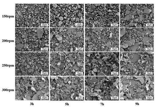
Figure 4. Micrographs (SEM, SE) of mixed 5 wt% nano-diamond reinforced 2024Al alloy composite powder fabricated under different ball milling conditions: the ball milling speed and process time. Reprinted with permission from [124]. Copyright 2021 Elsevier.
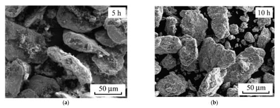
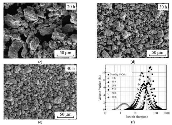
Figure 5. Morphology and particle size distributions of the powders ball milled at different durations: 5 h (a), 10 h (b), 20 h (c), 30 h (d), 40 h (e), the particle size distributions (f). Reprinted with permission from [125]. Copyright 2012 Elsevier.
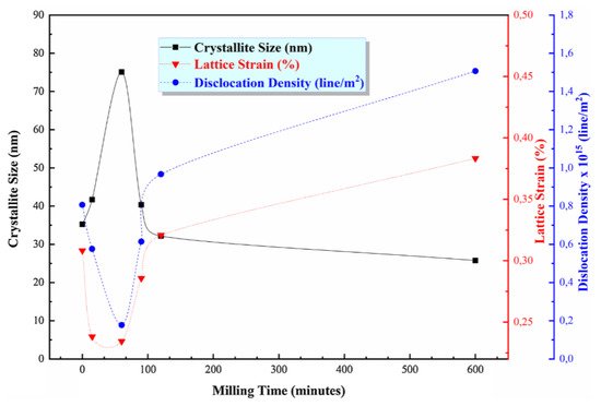
Figure 6. The variation of the crystallite size, lattice strain, and dislocation density of TiC/AA7075 powders estimated from XRD curves. Reprinted with permission from [126]. Copyright 2021 Elsevier.
Another method enabling the production of homogeneous nanostructured composite powder from submicron or nano-sized particles is spray drying. The process includes the following stages: (1) raw powders mixing to prepare slurry with the use of binder, (2) atomization of the slurry to fabricate composite powders and (3) heat treatment (also called calcination) of prepared powders. A wet ball milling can be used to blend the nano-sized particles homogeneously [134]. After atomization of the slurry, micro-sized nanostructured composite powders are received. However, powder morphology depends strongly on the spray drying process parameters, such as the rotating speed of nozzle, as well as inlet and outlet temperature. The final particle size and degree of sphericity of the as spay dried powders is affected by the rotating speed of the nozzle. Higher rotating speed promotes the refinement and the sphericity of the powders [134]. Afterwards, in the calcination process, organic additives are removed, and porosity is reduced. The final agglomerate grain size is usually in tens of micrometres. Kang et al. [100] used spray drying to produce 75W-25Cu wt.% nano-composite powder mixture with agglomerates size below 75 µm to achieve consistent powder feeding and a homogeneous deposit layer. It should be emphasized that spray drying enables to prepare powder dedicated to the CS process, where agglomerates are needed due to: (i) proper working of conventional powder feeder [135] and (ii) expected higher velocity to overcome bow shock formed above the substrate [100]. To increase the cohesion of agglomerated particles in cermet (e.g., WC-Co), powder sintering is suggested [136,137]. It is worth emphasising, that a major challenge in the nanosized powder mixture preparation is a uniform distribution of the ingredients, especially with a higher specific surface, e.g., carbon nanotubes (CNT) [77]. Bakhsi et al. fabricated aluminium–silicon eutectic alloy powder with an agglomerate particle size of 57 ± 21 μm containing multiwalled CNT, and they used it in atmospheric plasma spraying [99] and HPCS [138] (Figure 7). Nevertheless, to increase deposition efficiency in HPCS, spray dried powder was mixed with pure Al powder.
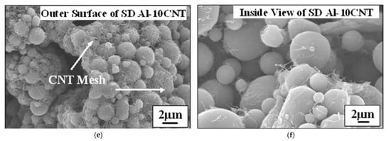
Figure 7. SEM micrographs of the spray-dried (SD) spherical agglomerates of SD Al-5CNT (a) and SD Al-10CNT powder (b), the outer surface of a single SD Al-5CNT powder (c), inside view of fractured SD Al-5CNT powder (d), the outer surface of a single SD Al-10CNT powder (e), and inside view of fractured SD Al-10CNT powder (f). Inset of (a) and (b) shows the powder size distribution. Reprinted with permission from [138]. Copyright 2009 Elsevier.
2.2. LPCS PRMMC Coatings Applications
PRMMC LPCS coatings combine various materials, resulting in advisable properties, e.g., good wear behaviour and increased fatigue strength, a high thermal conductivity combined with an increased creep resistance, great creep and corrosion resistance at high temperatures, as well as coupled high electrical conductivity and mechanical resistance [65].
Despite LPCS limitations, deposition of coatings with low porosity and high adhesion is possible, however, requires highly deformable powder materials and appropriate process parameters. Therefore, in metal –ceramic composites following materials are applied as a matrix: (a) aluminium [48,93,101,122,139,140,141], (b) copper [62,82,103,142,143,144,145], (c) zinc [81,144], (d) tin [81,105,106], or (e) nickel [63,68,146,147,148,149]. Other metals with higher mechanical properties can be deposited in the form of metal-metal composite, e.g., Fe/Al [150], Ti/Al [151], Ni/Zn [152], or by specific powder preparation method, e.g., DLC film by CVD on Ti powder [121]. Nevertheless, some materials are mixed for further intermetallic phase generation in additional PSHT [150,151,153].
The role of hard phase in metal–ceramic composites usually is played by ceramic powders, such as Al2O3 [48,101,109,111,112,140], SiC [82,107,108,113,154], B4C [115,146], WC [80,146,147] TiC [126,146]. The plastic deformation of impacting metallic particles is responsible for ceramic deposition due to mechanical interlocking in ductile metal. The high content (e.g., 50 wt.%) of coarse ceramic admixture (e.g., −30 µm) in initial powder significantly increases the probability of particles collision, fracturing and bouncing off. Consequently, more than 80 vol.% of the ceramic powder included in the mixtures usually rebounds, decreasing the volume of ceramics in the coating [62]. To increase ceramic content in the coating, the higher mass of ceramic powder should be mixed with metal. Melendez and McDonald [63] obtained 52 vol.% of WC particles in WC + Ni coating deposited with the use of 96 wt.% WC + 4 wt.% Ni powder blend mixture. The powder preparation method is meaningful as well. Feng et al. [115] mechanically blended Ni with B4C in various proportions. However, the ceramic content was always less than 20 vol.%. By powder cladding with the use of the CVD method, Feng et al. obtained a much higher deposition efficiency of B4C particles in the cold spray coatings. Ceramic content in the coating reached 44.0 vol.% for the NiCVD-87 vol.% B4C powder mixture. In one of my research [68], I coated Al2O3 with Ni to increase alumina content in the coating and to avoid the fracture of ceramic particles. As a result, the ceramic contribution in the coating sprayed with mechanically blended commercial Ni-Al2O3 and Ni coated Al2O3 increased from 7.3% to 30.5%. Nevertheless, ceramic content in the coating should be optimized to achieve expected properties. Zhang et al. [140] sprayed pure Al2024 and Al2024-Al2O3 composite coatings on 2024-T3 aluminium alloy substrate and noticed that the addition of 20 wt.% Al2O3 significantly increased the residual compressive stress (48.3 MPa) (Figure 8a) and adhesion strength (~50.68 MPa) and decreased porosity (0.55%) (Figure 8b) and surface roughness (11.82 μm) due to the tamping effect of metal powder by ceramics. However, increasing the ceramic content in the powder to 40 wt.% and 60 wt.% resulted in an increased presence of fractured Al2O3 particles inside the composite coating. As a result, enhancement of the material was limited.
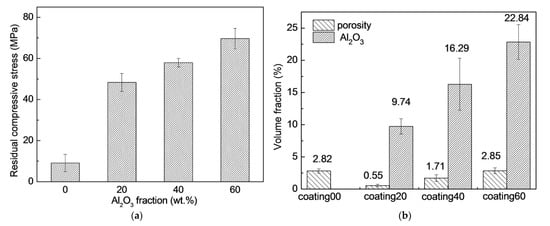
Figure 8. Residual compressive stress variations with different Al2O3 weight fractions (wt.%) on the surface layer (a), porosity and Al2O3 volume fraction (b) of the coatings. Reprinted with permission from [140]. Copyright 2019 Elsevier.
The conditions of LPCS make the process attractive for many applications. Previously, as a portable unit with a handy spraying gun, it was employed first of all for structural, dimensional, or functional restoration, and since the nozzle exit diameter is 5 mm, the work is precise without any additional masking. A good coating’s machinability ensures high surface quality with the possibility of on-site repair [64]. What is more, the method can be adapted to the recycling process and elongating selected products’ life cycle. In the field of art, LPCS can be applied as decoration of various panel natures including glass, rusty sheets of iron, copper plates. Different metal–ceramic feedstock powders are explored as paintwork due to possible metal colour mixing and surface topography modifications. Further applications of LPCS depend on the expected functionality and include mostly coatings with high electrical conductivity [103,145], electrochemical corrosion resistance [62,83,102,105], high-temperature corrosion resistance [155,156], wear resistance [79,157,158], solid lubrication [121,159], interlayers in welding or soldering processes [160,161], etc. The high quality of the coating and its properties arise from ceramic addition, which significantly reduces the porosity and increases the contact surface area of metal particles [122,162].
LPCS ensures uniform distribution of ingredients in dense PRMMC composite coatings and as a result high electrical conductivity and corrosion resistance. According to my previous research [62], ceramic admixture increases the surface contact between copper particles due to plastic deformation and as a result electrical conductivity up to 62.5% IACS. A further increase in electrical conductivity is possible due to the PSHT of the coating (Figure 9a) [62,145]. It should be noted that dense Cu-Al2O3 coatings with low porosity exhibit high electrical conductivity (about 90% of initial value) after salt-spray and Kesternich corrosion tests [82]. Moreover, copper–alumina composite coatings can significantly increase the corrosion potential of aluminium busbars due to the reduction of porosity and densification of the coating [62] (Figure 9b). Dzhurinsky et al. [163] examined aluminium, aluminium-alumina and aluminium-zinc-alumina coatings and demonstrated by accelerated corrosion test that corrosion of the sprayed composites intensified as the concentration of alumina particles increased within the coating. Wang et al. [162] tested by HPCS deposition of Al 5056-SiC mixture and concluded that SiC particles crack due to high-velocity impact and provide passage for electrolyte through inter-particle boundaries intensifying corrosion progress. On the other hand, Bai et al. [104] showed that the presence of Zn elements played a role in sacrificial anodic protection in Zn-Ni composite coatings and ensured higher corrosion resistance compared to pure zinc coatings. Therefore, the composite mixture should be matched to the designed application.
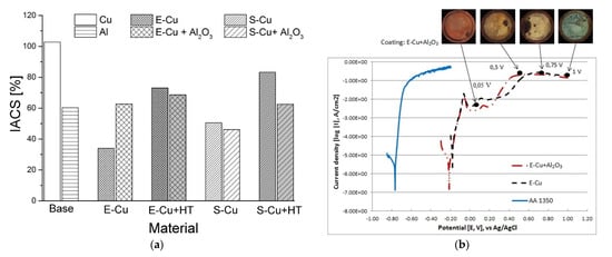
Figure 9. Electrical conductivity (a) and polarization behaviour (b) of LPCS coatings on AA1350 substrate. Powder designation: E—dendritic, S—spherical, HT—heat treatment of the coating. Reprinted with permission from [62]. Copyright 2017 Elsevier.
High-temperature corrosion-resistant coatings by CS are usually sprayed with the use of HPCS units [164,165,166]. The commonly applied powder material is Ni-based superalloy with chromium admixture, which has to block the penetration of corrosive species toward the substrate. Kilicay [156] applied Ni-Zn-Al2O3 to spray MMC coating on TZM alloy by LPCS. Kilicay chose Ni and Zn, which are very prone to oxidation and formed NiO and ZnO films on the coating surface. As a result, coating prevented contact of oxygen to the titanium-zirconium-molybdenum (TZM) alloy by the reaction of Ni and Zn with oxygen at high temperatures of 900 °C. The Al2O3 was chosen to densify the coating and improve coating adhesion. The specific mass changes of the TZM substrate and MMC coating at high temperature and air atmosphere is shown in Figure 10a. The mass of the TZM alloy sharply decreased by forming MoO3 oxide layers at temperatures above 600 °C due to the evaporation mechanism. The results showed that the Ni-Zn-Al2O3 MMC coating exhibited a remarkable oxidation resistance on the TZM alloy at the test temperatures. It is thus an interesting alternative for hot corrosion resistant superalloys coating, which was shown, e.g., by Zhang et al. [165] for CoNiCrAlY deposited with LPCS.
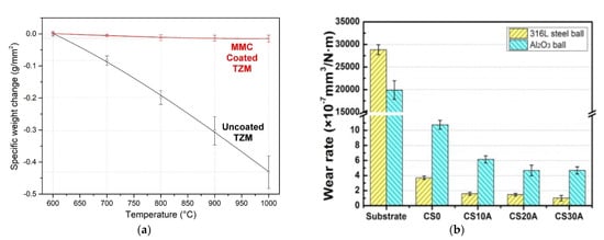
Figure 10. The specific mass changes of the TZM substrate and Ni-Zn-Al2O3 coating after high-temperature oxidation tests (a) (Reprinted with permission from [156]. Copyright 2020 Elsevier.) and wear rate in artificial seawater of CuSn5 + Al2O3 (0, 10, 20, 30 wt%) coatings and aluminium alloy 7075-T651 substrate (b) (Reprinted with permission from [143]. Copyright 2012 Elsevier).
The wear resistance of the coating is highly influenced by MMC composition. The most popular LPCS process mixtures (Al/Al2O3 and Cu/Al2O3) presents a relatively high coefficient of friction (COF) of 0.764 [84] and 0.88 [102], respectively. An optimization of spraying process parameters can decrease the COF value. For instance, Szala et al. [84] reported the COF of 0.555. What is more, Szala et al. obtained in the wear tests a superior slide wear resistance of Cu/Al2O3 coating K = 7.41 × 10⁻⁷ mm3·N−1·m−1. Wear resistance should be regulated by the content of the ceramic powder admixture. Chen et al. [143] examined the CuSn5–Al2O3 mixture and noticed that the wear rate of coatings decreases with the increase of Al2O3 content (up to 30 wt.%) and obtained very satisfactory results (see Figure 10b). Lee et al. [146] sprayed Ni mechanically blended with B4C, TiC and WC and analysed the effect of carbide particle momentum on coatings wear resistance. By the applied mathematical model Lee et al. showed that the momentum of WC particles was significantly higher compared to the other ceramic powder particles. Consequently, WC particles increased the level of work hardening of the nickel matrix. What is more, due to the higher fracture toughness of large WC (size of 36 ± 11 μm) particles and increased work hardening of Ni, the WC-Ni MMC coatings showed the lowest wear resistance. The proportion of metal–ceramic powders in PRMMC has a significant influence on the wear resistance of the coating. This statement was proven by Melendez et al. [147] who blended nickel with various contents of WC and showed that the wear rate of the coatings decreased significantly as the mean free path between the agglomerated WC particles decreased. The highest wear resistance, comparable to high-velocity oxygen fuel (HVOF) and HPCS WC-based coatings, Melendez et al. obtained for WC-Ni (96–4 wt.%) powder mixture, resulting in a 66–44 wt.% coating (Figure 11a). Furthermore, high ceramic content in PRMMC can promote other applications, such as steam reforming, which requires a catalyst with support. A popular couple would be nickel catalysts with alumina as support. The activity of the nickel-based catalyst is affected by the reduction degree of nickel species [167], while the alumina support is affected by a high specific surface area, providing a high dispersion of the metallic phase [168]. To assure high ceramic content, I sprayed by LPCS nickel-cladded alumina powder and obtained the coating with Al2O3 up to 30.5 wt% [68].
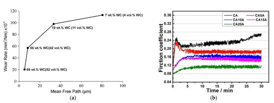
Figure 11. Curve of wear rate versus mean free path for various WC-Ni composite coatings (a) (Reprinted with permission from [147]. Copyright 2013 Elsevier.) and COF curves of (Cu-5Sn)/Al2O3-Ag coatings with various Ag content (0-20 wt.%) (b) (Reprinted with permission from [142]. Copyright 2020 Elsevier).
A great opportunity to decrease the COF gives the application of solid-lubricating coating. The most popular material is a mixture of metal [159,169] or metal-ceramic [170] powders with graphite powder. Okimura et al. [121] coated Cu spherical particles with diamond-like carbon (DLC) by CVD method for further usage in the LPCS process and concluded that the Cu-DLC composite coatings deposited from thin DLC-coated Cu particles behaved like a solid lubricant in the ball-on-disk tests. For the protection of moving parts in seawater conditions, Chen et al. [142] applied to silver in the metal–ceramic mixture and sprayed (Cu-5Sn)/Al2O3-Ag solid-lubricating LPCS MMC coating. Silver, similar to graphite, presents low friction and wear in artificial seawater environments. Via the controlled addition of silver powder, up to 20 wt.% Ag, the COF of the coatings was significantly decreased (Figure 11b).
The LPCS can also solve the difficulties of joining materials with low weldability. Due to significant differences in physical and chemical properties, such as melting and boiling temperature, coefficient of thermal and electrical conductivity, an oxide layer, the limited mutual solubility resulting in heterogeneous solutions at room temperature, thermal expansion mismatch, and suitability at higher temperatures, dissimilar materials show low bond strength [171,172,173]. As a result, the formation of bulky and directional intermetallic compounds detrimental to the joint occurs [173,174,175]. Among various joined construction materials, aluminium and steel are very popular. However, the resistance spot welding (RSW) joint of these metals is characterised by reduced mechanical properties resulting from the brittle intermetallic phases [176,177]. To prevent the formation of the hard phases, a smooth transition zone between two different metals by an intermediate layer can be obtained [177,178,179,180,181]. Nevertheless, most of the applied methods are based on large-area coating. LPCS enables coating a precise area of the material before welding. Analysing the material for the aluminium-steel intermediate layer I proposed free materials: Al-Al2O3, Ni-Al2O3 and Al-Ni-Al2O3 to analyse the formation of advisable Al-Ni intermetallic phases inside the coating [160]. Nevertheless, Ni-Al2O3 interlayer showed after welding the most uniform microstructure and as a result, the highest shear strength comparable with the aluminium + aluminium joints (Table 1). Furthermore, the fracture out of the welding nugget zone indicated a higher strength of joint than the aluminium base material. Wojdat et al. [161] applied multi-layered coatings as an interlayer in the soldering process of aluminium alloy to graphite. The graphite was coated by soft aluminium, then densified by Al-Al2O3, to be finally sprayed by copper coating. The aluminium alloy was coated by copper as well and soldered by tin to multi-layered graphite. The metallic (e.g., Al and Cu) and PRMMC (e.g., Al-Al2O3 and Cu-Al2O3) composites, LPCS interlayers effectively limits formation of the reaction zones in soldering process and improves the mechanical properties of the joint [182]. It is worth emphasising that pure metal coatings are better intermediate layers in the soldering process [182,183,184,185]. Nevertheless, ceramic particles present on the LPCS coating surface limit soldering properties, such as the wettability of the composite interlayer with Zn–Al solder, which eliminates the use of Al-Al2O3 powder in the soldering process [183].
Table 1. Results of steel-aluminium tensile shear force measurements of RSW joints [160].
| Scheme | Interlayer | Coating Thickness [µm] |
Shearing Force [N] | Fracture |
|---|---|---|---|---|
| 1.1 | Al + Al2O3 | 250 | 1080 | Cohesive |
| 1.2 | 500 | 625 | Adhesive, cohesive | |
| 2.1 | Al + Ni + Al2O3 | 250 | 2400 | Adhesive |
| 2.2 | 500 | 2500 | Adhesive | |
| 3.1 | Ni + Al2O3 | 250 | 3060 | Base material |
| 3.2 | 500 | 2850 | Base material |
The LPCS can be combined with a magnetron sputtering (MS) process to produce transparent and conductive thin films. The MS can be used to deposit a variety of materials. Nevertheless, some ceramic coatings (e.g., indium-tin-oxide (ITO)) requires ceramic or metallic feedstock, called target. The ceramic In2O3-SnO2 sinter provides higher performance and thus is more frequently applied than metallic In-Sn. Nevertheless, the sinters are soldered to the copper carrier disk and show a tendency to wrap or crack due to differences in thermal expansion coefficient [186,187]. To solve this problem, I produced a composite Sn-In2O3 target by LPCS coating [117,118]. Due to the oxidation of Sn before spraying, an additional SnO phase was obtained in the coating. Deposited LPCS coatings showed mean thickens of 1 mm with uniform distribution of indium oxide and tin particles. Finally, high-quality ITO transparent thin films on glass substrate were obtained in the MS process, with the highest transmission of 88% at λ = 550 nm and the lowest resistivity of 0.03 Ω·cm.
Functional graded PRMMCs coatings can be sprayed by LPCS as well. As shown in one of my previous papers [103], the 3 mm thick Al-Al2O3 coating on steel substrate had microhardness variations through the thickness from 83.7 HV0.3 next to the substrate up to 129.5 HV0.3 in the top part (Figure 12). It arose from the thermal recovery of the aluminium in the lower part of the composite coating as multi-layered spraying of thick coating. In this way, the coating gained high hardness on the surface while being ductile at the coating/substrate interface. Adebiyi et al. [154] sprayed a mixture of Ti-6Al-4V with SiC powder by LPCS process. Deposited coatings were free of phase transformations, decarburization, or decompositions. The high impact of the blend resulted in microstraining, amorphization, and grain refinement. The hardness was improved from 291 ± 13.9 HV0.3 in the substrate to 652 ± 12.7 HV0.3 in the coating due to the partially homogeneous distribution of SiC. What is more, the hardness and other mechanical properties can be increased by using nanostructured coatings, deposited by nano-sized powders [188].
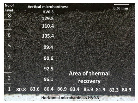
Figure 12. Microhardness distribution in 3mm thick Al-Al2O3 composite LPCS coating. Reprinted with permission from [101]. Copyright 2016 Elsevier.
The LPCS can be coupled with laser [65,189,190,191,192] or friction stir processing (FSP) [193,194,195,196,197] treatment to improve structure of as-sprayed coating. In a laser-assisted low-pressure cold spraying (LALPCS) process the cold spray spot interacts with the laser irradiation on the substrate and as a result, local temperature rises (Figure 13). Kulmala et al. [65] used LALPCS to spray copper-alumina and nickel-alumina coatings and found that laser irradiation increased deposition efficiency and densification of the coatings. Moreover, copper-alumina coating open cell potential was near bulk potential (Figure 14a). Another surface modification technique, friction stir processing (FPS), shows great capability in improving materials structures, quality, and preparing the surface of metal–matrix composites [195,196,197] (Figure 15). Hodder et al. [198] applied friction stir processing to modify as-sprayed LPCS Al-Al2O3 and found that the particle mean free path decreased significantly due to the re-distribution of the Al2O3 particles trapped within the Al matrix, and consequently increased load share and microhardness values. Khodabakhshi et al. [199] fabricated a dense titanium coating with refined grain structure by combining cold spraying and FSP. The optimization of the plunge depth of the FSP head resulted in compressive residual stresses with a maximum negative value of around 400 MPa at the advancing side. What is more, Khodabakhshi et al. concluded in another research [200] that the bonding mechanism between aluminium substrate and titanium particles in CS was reinforced by a chemical bonding. Due to material mixing and deformation, the solid-state chemical inter-diffusion of elements occurred during FSP (Figure 14b). Consequently, the Al3Ti intermetallic layer with a thickness of ~10–20 nm formed inducing nano-scale interfacial chemical bonding. The formation of intermetallic phases that increase hardness of the coating is possible by conventional PSHT of the coating in the furnace. In this case two reactive metal powders (e.g., Al and Ni) should be mechanically blended and LPCS sprayed. Nevertheless, high porosity forms in the coating. To eliminate the porosity, I proposed resistance spot welder (RSW) heat treatment with simultaneous compression of the electrodes [153]. As a result, the porosity of the coating decreased from 20.8% to 4.6% in conventionally and RSW heat-treated coatings, respectively.
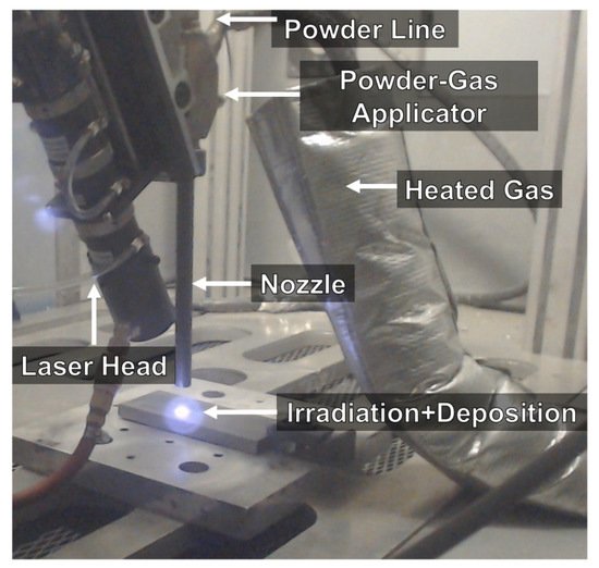
Figure 13. Overview of the LACS process. Reprinted with permission from [190]. Copyright 2020 Elsevier.
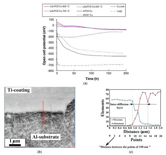
Figure 14. Open-cell potential versus time for the LALPCS and LPCS Cu+Al2O3 coatings and as references were HVOF sprayed Cu coating, bulk Cu and substrate material Fe 52 (a) (Reprinted with permission from [65]. Copyright 2008 Elsevier.) the SEM image from Al-Ti interface showing the indexing points for Auger analysis (b) and Auger electron spectroscopy line-scan analysis results from the interaction zone at the interface (c) (Reprinted with permission from [200]. Copyright 2018 Elsevier).
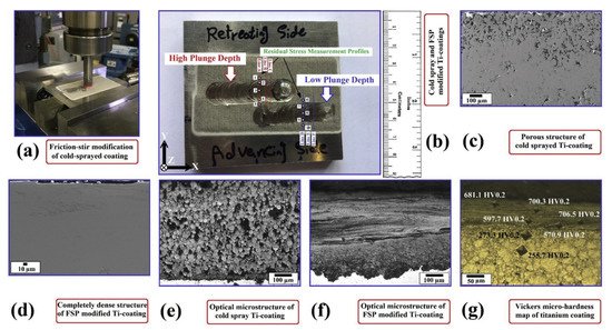
Figure 15. Schematic implementation of FSP on the surface of CS titanium coating (a), top-view macro-image from the prepared coating layers after two-steps cold gas spraying and friction-stirring showing the measurement profiles for residual stress (b), FE-SEM images (c,d) and optical microstructures (e,f) from the porous CS sprayed titanium (d,f) coating and (d,f) friction-stirred one, respectively, indentation Vickers micro-hardness profile close to the surface of produced modified coating layer (g). Reprinted with permission from [199]. Copyright 2019 Elsevier.
Table 2 shows the main applications of PRMMC coatings produced by LPCS.
Table 2. Selected applications of the LPCS PRMMC coatings.
| Powder Material | Powder Preparation Method | Coating Application | Reference |
|---|---|---|---|
| Al2O3-Cu | Mechanically blended | Corrosion protection, electrical conductivity, wear resistance | [62,82,84,103,145] |
| Al2O3-Al | Mechanically blended | Corrosion protection, wear resistance, intermediate layer for dissimilar materials joining | [83,84,101,161,163] |
| WC-Ni | Mechanically blended | Wear resistance | [63,147] |
| Al2O3-Ni and Al2O3-Ni-Zn |
Metal cladded ceramics or mechanically blended | High temperature corrosion resistance, steam reforming, intermediate layer for dissimilar materials joining | [68,104,156,160] |
| Al2O3-Cu-graphite and Al2O3-(Cu-5Sn)-Ag |
Mechanically blended | Solid-lubricating coatings | [142,170] |
| In2O3-Sn | Satellited | Targets for magnetron sputtering | [117,118] |
3. LPCS All-Ceramic Coatings
Ceramic materials are characterized by more complex structures than metals. The ionic and covalent bonding assures high strength and hardness, low thermal conductivity, or chemical inertness characteristics [201], and thus these are common and versatile types of coating applied in thermal spraying processes. Various compositions of ceramic materials (fed separately or as a mixture) form coatings applied as active layers to improve optoelectronic, photocatalysis, biocompatibility and mechanical properties such as hardness, friction, abrasion resistance, thermal and electrical insulation, corrosion resistance, and thus increase the lifetime of coated parts [202]. In the wide group of processes dedicated to ceramic coatings deposition, thermal spraying stands out due to: (i) unlimited substrate dimensions and complex shapes, (ii) stable stoichiometry of the material, (iii) high deposition efficiency, (iv) low operation costs and the most important high range of coating’s thickness, from hundreds of nanometres to several millimetres [203]. The capability to deposit thick ceramic coatings is another crucial advantage to protect the substrate from premature degradation as a result of wear [204,205], corrosion [206,207] or high-temperature [208,209], etc.
However, in the conventional thermal spray processes (e.g., atmospheric plasma spraying or high-velocity oxygen fuel) the high process temperature leads to a melting of the applied material or its intensive heating with a heat source. As a result, a change in particle shape, an increase in powder particle size, phase transitions (e.g., anatase to rutile, which is less photocatalytically active), structural modification or technological defects such as porosity or micro-cracks are generated [210,211,212,213,214]. Eventually, the melted particles lose the characteristics and properties of the nanostructured material. Therefore, low-temperature, kinetic-based processes are sought to improve the coating’s quality and fill the gap. LPCS and its vacuum modification AD are the most promising methods. The coatings deposition in these techniques relies on the mechanical interlocking and adhesion of the fine particles resulting in: (i) unmodified feedstock phase composition, (ii) undamaged substrate from input heat, and (iii) dense layer with unaffected powder properties [73]. Both methods enable efficient ceramic spraying. However, a proper powder preparation is needed.
3.1. Powders Preparation
The bonding mechanism of metallic particles in LPCS is attributed to plastic deformation at a high strain rate. The impacting metal particles show the highest shear strain at the particle’s interface [215,216]. In contrast, the mechanism with plastic and features of inelastic deformation may occur for ceramics. However, fine particles have to be applied in the deposition process [39,40]. What is more, due to high-velocity ceramic particle impact, a shear strain spreads as a shear cone towards the particle centre and the maximum is obtained inside the particle. Therefore, the strain distribution in AD is much less localized than that of LPCS. Particles impact simulations performed by Daneshian et al. [40] revealed three different impact behaviours in the AD process: (i) rebounding, (ii) bonding and (iii) fragmentation. However, bonding occurred only for small particles of 25–75 nm, while particles larger than 75 nm were fragmented and rebound (Figure 16). It should be noted that LCPS operates at higher pressures than in AD due to the ambient atmosphere, and thus generates the bow shock in front of the substrate decelerating the particles. This phenomenon limits the application of fine ceramic particles in LPCS, as the particles would not reach the substrate. There are several requirements for powder preparation to spray ceramic particles by CS [74]: (i) nanosized particles should be agglomerated to min. 15 µm in diameter to pass through the shockwave, (ii) the agglomerates should be porous, and (iii) they should have structures with a continuous epitaxial-like crystal array across a plurality of primary particles, so that the particles can be easily fragmented and adhere during impact.
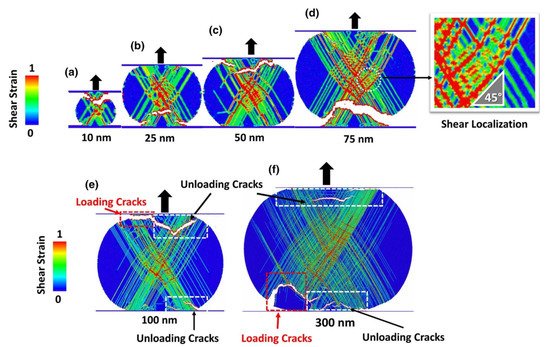
Figure 16. Simulated deformation patterns after compression loading and unloading (deformation history) by Von Mises shear strain fields inside the TiO2 particles for different initial diameters of (a) 10 nm, (b) 25 nm, (c) 50 nm, (d) 75 nm, (e) 100 nm and (f) 300 nm. The strain pattern reveals (i) localized plastic deformations along the slip systems and (ii) shear localization in an orientation relation of 45° with respect to the loading direction. [40].
The phenomena present during the deposition of ceramic particles by AD are similar to those occurring during LPCS. Hanft et al. [73] divided particles by the size and stage of agglomeration and described possible processes in AD (see Figure 17a). The ceramic particles size ready to bond is in the range of 200 nm—2 µm at intermediate energies. As the submicron particle strikes the substrate, cracks form by whole volume and fragmentation occurs due to impact pressure. Further moving or rotating of the fragments provides arrangement and densification. Upcoming particles cause rebinding of fragments, further plastic deformation and consolidation of the deposited material. The plasticity is described by quasi-static compression and respectively determined thresholds for plasticity [217]. Ceramic agglomerates impact the substrate and due to the kinetic energy get separated into fragments. The coating formation is possible, however the quality can be worsened. Large agglomerates will erode the substrate and rebound. The coating formation can be divided according to Figure 17b into stage (1), which concerns particles impact, substrate deformation, and anchoring of the first layer, and stage (2) with subsequent film growth and particle consolidation.
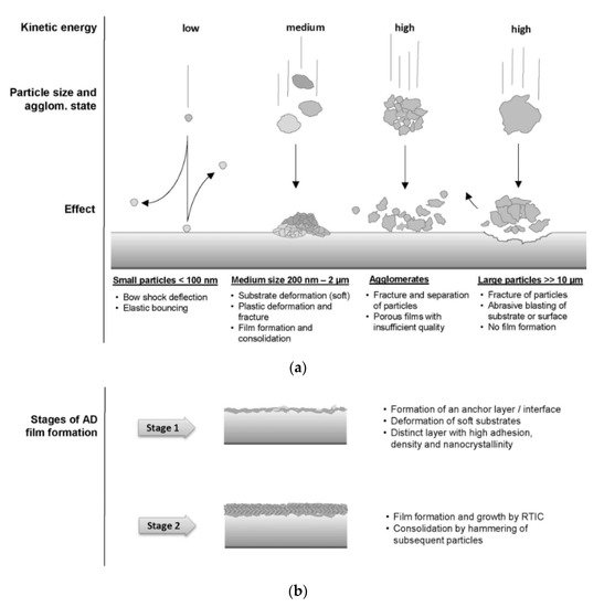
Figure 17. Possible particle-substrate interactions based on the speed and kinetic energy of the ceramic particles (a) and the room temperature impact consolidation process, with a distinction between stage 1 (anchor layer formation) and stage 2 (film buildup), during which particle hammering and fracturing takes place (b) [73].
The LPCS spraying process is performed at low temperatures, and thus there is an opportunity to use thermally sensitive materials without possible burning. To prepare ceramic powders with desired characteristics dedicated for LPCS (e.g., high purity ultrafine-grained powders and nanopowders), the following wet-chemical methods can be used: wet ball milling, chemical co-precipitation, spray drying, or sol-gel. Wet ball milling performed in alcohol provides an efficient environment for homogenous mixing and enables a uniform distribution of components with additional satelliting [218]. As a result, wet-milled samples have a significantly smaller standard distribution compared to air milled [219]. Saghir et al. [220] ball-milled 5 µm sized plate-like alumina powder with various parameters in air and ethanol. Saghir et al. noticed that wet-milled powders underwent the greatest size reduction with a final average particle size of 0.29 µm and crystallite size of 10.13 nm (Figure 18), while Xu et al. [221] wet-milled ZnO varistor ceramics doped with Bi2O3, Sb2O3, Co2O3, Cr2O3, and MnO and achieved grain refinement. Turon-Vinas et al. [222] mixed in ball mill ceria-stabilized zirconia powders with 10 and 12 mol% ceria, containing 0.25 wt.% of Al2O3 with different amounts of CaO in ethanol. Turon-Vinas et al. dried the powders, sieved (315 μm mesh), applied in cold isostatic pressing and proved increased mechanical properties of the material due to reduced grain size. The fine powder resulting from wet ball milling provides high density (above 99%) ceramic compacts in the sintering process [223].
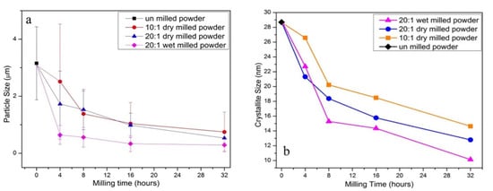
Figure 18. Particle size of plate-like alumina powders ball-milled with different parameters (a) and comparison of crystallite size (b). Reprinted with permission from [220]. Copyright 2021 Elsevier.
Chemical co-precipitation is applied to homogeneous hydrolysis of various oxides. Many papers in the literature describe the production of nano-crystalline ceramic materials, e.g., ThO2 [224], cerium doped gadolinium gallium aluminium garnet with different Y-doping levels [225], low-agglomerated Yt-doped yttria-alumina garnet (YAG) (Figure 19a) [226], Ce-doped YAG nanophosphors [227], and barium calcium zirconium titanate (BCZT) ((Ba0.85Ca0.15)(Zr0.1Ti0.9)O3) with a homogeneous particle size of approximately 500 nm (Figure 19b) [228].
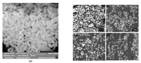
Figure 19. FESEM micrographs of the Yb:YAG ceramic nanopowder fabricated by chemical co-precipitation (a) (Reprinted with permission from [226]. Copyright 2019 Elsevier) and (b–e) SEM images of BCZT powders with different NaOH concentrations (Reprinted with permission from [228]. Copyright 2019 Elsevier).
A method enabling control of agglomeration size of ceramic nanoparticles is spray drying. Powders prepared by spray drying have good flowability, narrow size distribution and controllable morphology. Produced in this way powder has granulation from tens of nanometres to hundreds of micrometres and depends mostly on the atomization nozzle type. However, it should be noted that the morphology of resultant particles depends not only on the size distribution of initial ceramics but also on agglomeration tendency in the suspension and mechanical strength of the shell of a granule provided by polymer additives during the drying process [229]. The influence of binder on the morphology was analysed by Kim and Jung [230], who concluded that the sphericity of Al2O3-ZrO2 particles is improved with increasing the viscosity of the solution. On the other hand, Wang et al. [231] produced hydroxyapatite (HA) microspheres and found that the particles had spherical morphology and smooth surface (Figure 20), but did not have uniform size distributions. The mean size of the particles increased with slurry concentration and compressed air flow rate. Many studies have described the optimization of powders by spray drying for further application in thermal spraying. Bertrand et al. [232] prepared agglomerates of two oxide ceramics (Al2O3 and Y2O3–ZrO2) and shown that there is a qualitative relation between the sedimentation behaviour and the agglomerate shape (solid or hollow), while Vicent et al. [233] applied spray drying to produce free-flowing micro-sized nanostructured agglomerated TiO2 powder (P25 mixture of anatase and rutile) from nanosized particles with an average primary size of ~20 nm for atmospheric plasma spraying process. Chahal et al. [234] used the spray drying process to prepare calcium carbonate powder for thermal spray processes and obtained large, porous, hollow, and spherical particles ranging between 14 and 201 μm. However, in this case, the powder had to be sieved before the spraying process. To solve the problem of particle pores, density, and size, Bian et al. [134] prepared by spray drying a nanostructured mixture of Al2O3–13 wt.%TiO2 composite powders, and then heat and plasma treated. The pores in the particles were decreased after heat treatment, while plasma treatment increased the density and maintained a large number of nano-sized grains (Figure 21).
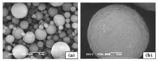
Figure 20. SEM micrographs of hydroxyapatite microspheres fabricated by spray drying: (a) overall morphology, (b) high magnification surface morphology. Reprinted with permission from [231]. Copyright 2009 Elsevier.
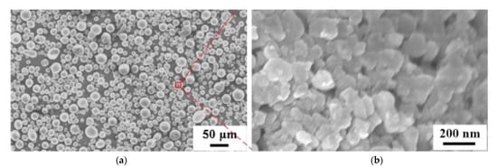
Figure 21. SEM micrographs of the plasma-treated spray-dried Al2O3–13 wt.%TiO2 powders: (a) overall morphology, (b) high magnification surface morphology. Reprinted with permission from [134]. Copyright 2012 Elsevier.
The sol-gel (SG) method offers unlimited possibilities for producing different materials at room temperature. It is essential for organic or biological modifications because it does not cause thermal degradation of materials [235]. There are alternative high-temperature approaches, such as the Pechini method [236] or the combustion method [237]. The SG technique also offers unique possibilities for generating materials with different shapes because the process is performed in the liquid medium. Matrices produced in this way can be porous or dense, depending on the final application. Porosity in a material is essential for potential applications, especially when active substances change their physicochemical properties (e.g., colour) in contact with extrinsic factors (gas and liquid) coated inside the matrix. Precursors offer numerous possibilities of modification of final products by adding functional groups. As a result, material properties can be changed, e.g., the affinity of metals, flexibility, or hydrophobicity [236,238,239]. It is worth emphasizing that the drying step, when water and other volatile liquids are removed, can be performed at room temperature. The resulting dry amorphous powder forms agglomerates consisting of the particles linked by electrostatic or van der Waals forces. However, uncontrolled room temperature drying and ageing remove organic liquids incompletely. The synthesis remains play a role of organic binder holding particles together and can be used in powders preparation suiting LPCS [240,241,242]. Considering the strength of the attractive force between particles, two types of agglomeration can be distinguished, namely soft and hard.
In non-sintered soft agglomerates weak liquid bridge forces hold the particles together, while in the case of sintered hard aggregates, particles are bound due to chemical diffusion. The hard agglomeration generates problems with breaking down during compaction, which results in incomplete densification of the particles [243]. This may be troublesome for LPCS needs agglomerated particles of a specific size to overcome the bow shock and form a coating.
In the literature, many reports concerning various ceramic materials produced via SG can be found, e.g., ZrO2-MgO nanocomposites [244], ultrafine alumina powders (<10 nm) [245], AlON powders by the nitritation of SG-derived alumina nanoparticles [246], nanoscale ZnTiO3 powders [247]. In some papers, SG is paired with thermal spraying methods, of which plasma spraying is most recently applied. The SG enables various modifications of powder particle surfaces to increase the thickness of thermally sprayed coatings or enhance the adhesion force between the coating and substrate (Figure 22) [248]. However, due to nanosize combined with light weight and low density, the thermal spray coating process of nanopowders is characterized by poor flowability, leading to limited deposition and uneven coating thickness. In this case, SG can provide nano-sized powder (e.g., yttria stabilized zirconia (YSZ)) and bind its particles to microsized agglomerates by polyvinyl alcohol [249,250].
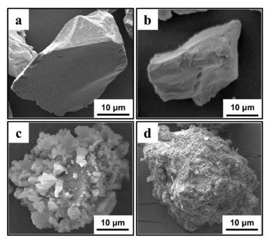
Figure 22. SEM images of commercial-SiC powder (a), commercial Al2O3 powder (b), SG fabricated TEOS_SiC powder (c) and SG fabricated TEOS/SDS_SiC powder (d). Reprinted with permission from [248]. Copyright 2020 Elsevier.
Powders produced by SG can be dried in various temperatures to obtain various polymorphs, for instance, TiO2 amorphous powder can be produced by drying at room temperature, while anatase and rutile by drying the same powder at 500 and 800 °C, respectively. In my previous research, I produced nanosized TiO2 powder particles of spherical shape with sizes up to 500 nm [240,241,251]. The size of produced agglomerates was in the range of 3.6–78.6 μm (D 0.5 = 35.9 μm), 3.4–70.4 μm (D 0.5 = 19.4 μm), and 6.9–96.7 μm (D 0.5 = 35.9 μm), for amorphous phase, anatase, and rutile powder, respectively. The amorphous agglomerates seemed to be more porous compared to anatase or rutile (Figure 23). The size of powders was appropriate for LPCS. What is more, proper modifications ensured particles surface functionalization, e.g., by providing fluorinated groups to obtain coatings with superhydrophobic properties in further work with LPCS (Figure 24) [242]. The spraying conditions (e.g., low process temperature) minimize the heating of the powder in the working gas stream and preserve the functional material from burning or decomposition.
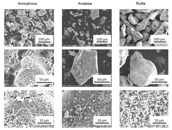
Figure 23. Micrographs (SEM, BSE) of SG TiO2 various polymorph powders after synthesis. Reprinted with permission from [240]. Copyright 2019 Elsevier.
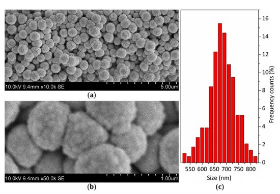
Figure 24. SEM image of SG fabricated SiO2–F powder (a) with a detailed view on FOTS-functionalized cauliflower-like silica spheres (b) and histogram of particle size distribution based on SEM imaging (c) [242].
The nanoparticles agglomeration can be improved by adding a binder. Yang et al. [252] deposited TiO2 coating with a mean thickness of 10–15 µm using anatase particles agglomerated by polyvinyl alcohol binder. Salim et al. [253] produced anatase powder by hydrolysis of TiOSO4 in distilled water with a small addition of inorganic salt (ammonium sulfate) working as a binder combined with hydrothermal post-treatment process and sprayed 150 µm thick TiO2 coating. Salim et al. claimed that NH4+ and SO42− ions adsorbed on the surface of TiO2 and post hydrothermal post-treatment favour agglomerated particles break down on impact onto the substrate due to the induced nanoporosity and were the key factor to a build-up of the coating. Further analysis performed by Toibah et al. [254] showed that adding the (NH4)2SO4 binder enhanced the agglomeration process of TiO2 and promoted mobility of dislocation during the CS process. It should be emphasised that soft agglomerates provide higher quality coating compared to sintered aggregates, which are difficult to fracture upon impact [73,255,256].
3.2. LPCS Ceramic Coatings Applications
Ceramic nanostructured coatings are a fundamental material of many functional applications, such as self-cleaning and antifouling surfaces [257], implants and biocompatibility [258], biomedical devices [259], tools [260], solar cells, Li-ion batteries, and solid oxides fuel cells [261]. Particular attention is paid to the nano-porous structures, which merit is extremely large surface area and other specific properties in comparison to bulk material [262]. Kinetics processes enhance ceramic particle’s breaking into small fragments within coatings with defined density. As a result, some local porosity can be formed in the coatings [240,241]. What is more, due to high-velocity impact, impact-induced fragmentation and compression in LPCS, nanoparticles ceramic particles can provide coatings with various thicknesses [263]. In contrast to the AD method, LPCS work in atmospheric conditions and a shock wave is formed above the substrate. Therefore, agglomerated particles are needed in LPCS to enhance DE.
Deposition of ceramic particles requires specific parameters. High pressure above 2 MPa enables anchoring of the ceramic particles in a plastic substrate, however, incoming particles cause blasting effects resulting in defects and thin thickness of the coating [73,254]. Deposition of ceramics by LPCS is conditioned significantly by powder preparation method [240,241]. Amorphous agglomerated particles manufactured by the SG method and dried at room temperature showed high porosity and residue of organic binder, composed mostly of alcohol, which enabled compaction of the submicron powder particles. Application of high working gas temperature of 400 °C in LPCS resulted in crack-free and thick coating formation with amorphous TiO2 to the anatase phase transition. According to the literature [263,264,265,266,267,268] amorphous oxides, known as soft ceramics, are exhibiting remarkable plastic deformation at moderate temperatures.
CS, as a dynamic process, generates enormous amounts of kinetic energy, which is transformed into plastic deformation and enables phase transition. Therefore, controlled transitions of amorphous to crystalline phase are possible (Figure 25). The phase transition of amorphous material can be controlled by the volume fraction of the crystalline phase, which prevents propagation of the cracks and supports the formation of multiple shear bands [269,270]. Moreover, the deformation of amorphous ceramic can be influenced by the coexistence of the amorphous phases and crystalline phases [269,270,271,272]. Xu et al. [272] analysed amorphous ceramics in hot pressing and concluded that amorphous ceramic, as a metastable material, shows large atomic mobility and local free volume, enabling the formation of shear bands and further plastic deformation. Therefore, the mechanism responsible for ceramic deposition is based on (i) slipping or sliding of fine particles over particles and (ii) plastic deformation resulting from the amorphous state with larger atomic mobility and local free volume, which is beneficial to the formation of shear bands.
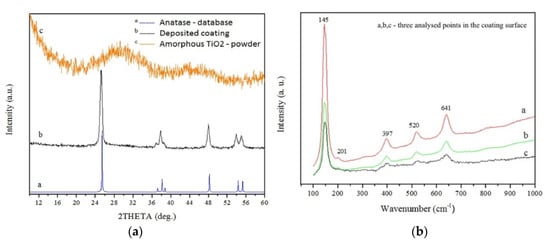
Figure 25. XRD (a) and Raman (b) spectra obtained for coating deposited of amorphous powder with the use of air preheated to 600 °C. Reprinted with permission from [240]. Copyright 2019 Elsevier.
It is worth emphasising that the mechanical properties of coatings strongly depend on the type of feedstock powder and the substrate preparation method as well. The amorphous powder with an organic binder enables the deposition of a coherent coating without structural defect [240,241]. According to my previous results [251], the adhesion measured by a scratch test of anatase LPCS coating sprayed of amorphous titania powder dried at room temperature was highest among other analysed coatings. The critical load of 15.8 N was achieved (Figure 26). The result was comparable to the adhesion of suspension plasma sprayed rutile coating, which showed a critical load of 16.56 N [273]. Unfortunately, coating sprayed of anatase powder showed many defects (e.g., lamellar microcracks) which resulted mainly from differences in the thermal expansion coefficient of the metallic substrate and ceramic coating. Similar problems with microcracks and delamination of anatase coatings on steel substrate were noticed by Yamada et al. [274] when using nitrogen as a working gas. The coating quality was improved by applying helium.
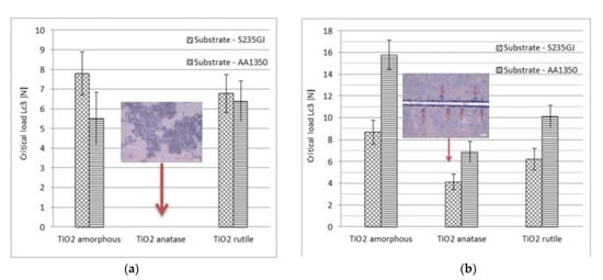
Figure 26. Critical load Lc3 results obtained for coatings deposited onto the ground (a) and grit blasted substrate (alumina grain size of D50 = 30 μm) (b). Reprinted with permission from [251]. Copyright 2021 Elsevier.
Due to coatings purity, controlled phase and porosity, high adhesion and cohesion, LPCS can be applied to spray many ceramic materials. The TiO2 coating deposited on a metallic substrate improves surface properties, such as self-cleaning, anti-corrosive, or photocatalytic activity. Great potential in the processes of photocatalytic decomposition of organic pollutants gives amorphous titanium dioxide [275,276,277,278] and mixtures of crystalline polymorphs with amorphous TiO2 [279,280]. It arises from specific amorphous material properties, which favours the photocatalysis process: (i) the oxygen vacancies and defect states can promote the generation of photo-induced holes and hinder the recombination of electron-hole pairs and (ii) a high specific surface area and a large number of surface reaction sites of amorphous form make the reactive surface larger than in the case of anatase [281,282]. It should be noted that the long-term operation of anatase-amorphous coatings on the aluminium substrate in a high humidity environment affects its photocatalytic activity by the amorphous transition to the anatase-brookite mixture [283]. The crystallization of brookite was activated by two factors interacting at the same time namely oxygen defects of amorphous TiO2 and the effect of moisture on this specific system. The degradation efficiency of methylene blue after 4 h of UV irradiation by anatase-amorphous and anatase-brookite coatings was 22% and 34%, respectively [283]. Zhou et al. [284] deposited by the LPCS process an agglomerated gallium nitride (GaN) nano-porous, thin coating (up to 10.4 µm) on stainless steel and achieved photocatalytic activities of about 33%. The obtained result was 9% higher compared to the powder and arose from the higher specific surface area and roughness that the coatings exhibit after the breakage of the particles during the cold spray. It is worth emphasizing that LPCS can be used to spray TiO2 onto thermally sensitive materials, such as polymers, providing new opportunities for coupled materials [285]. Fan et al. [286] sprayed nanocrystalline TiO2 by the vacuum AD process and obtained a similar coating consisting of agglomerated particles with a thickness of several hundred nanometers and a mesoporous microstructure for applications as photocatalytic degradation and dye-sensitized solar cells.
Ceramic coatings can be also applied successfully for biomedical applications [287,288,289]. Hydroxyapatite (HA) compared to titanium shows high bioactivity due to increased osseointegration capacities and similar chemical composition of the bone [290]. LPCS can restrain temperature drawbacks present in plasma spraying of HA, such as evaporation, phase alteration, residual stress, deboning or gas release [291]. Vilardell et al. [292] worked on Ti6Al4V substrate preparation to successfully spray hydroxyapatite (HA). The best quality and DE showed HA coatings deposited by LPCS onto a very rough and porous HPCS Ti bond coat. The HA particles impact the bond coat surface and anchor properly by filling up the valleys of the surface roughness. According to the dilatometry graph, two different thermal treatments were performed at 1000 and 1400 °C to densify the coating structure (Figure 27). Apart from substrate surface roughness, there are other process parameters, such as standoff distance, substrate heating temperature, and the number of sprays, which influences the HA coating properties. Moreover, despite the ideal bioactive compatibility of HA, low mechanical strength limits its use in loaded implants. Therefore Hasniyati et al. [293] used the design of experiment and analysed the effects of input LPCS process parameters on the thickness, nanohardness, and elastic modulus of the HA coating deposited on pure Mg. The optimized HA coating was 49.77 μm thick, with nanohardness and elastic modulus of 462.61 MPa and 45.69 GPa, respectively.
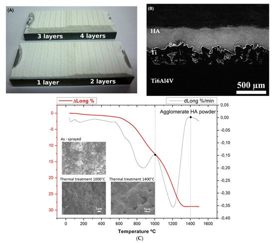
Figure 27. Macrograph (A), micrograph optical image (B) and dilatometry of HA coating (C) obtained by LPCS on Ti bond coat. Reprinted with permission from [292]. Copyright 2018 John Wiley and Sons.
The particles agglomeration was used to spray other types of ceramic materials by LPCS, such as WO3, SiC, SiO2. Tungsten trioxide is mostly applied for: (i) hydrogen detection, (ii) fuel cell electrodes, (iii) photoanodes in photoelectrochemical cells for water splitting, pollutants degradation, air purification, and as an antimicrobial agent [294]. To produce WO3 coatings, Lee et al. [295] sprayed aggregated particles of 30–50 µm size, which were shattered and fractured upon impact on the substrate. Formed coatings had a thickness of up to 2 µm and consisted of very fine secondary particles, which provided good adherence and void reduction in the coating. In another study, Lee et al. tested WO3 and Y2O3 LPCS coating and noticed, that particles closest to the substrate were finer and better packed due to fragmentation of impacting agglomerates (Figure 28) [296]. The SiC is applied for anti-oxidation at elevated temperatures due to thermophysical properties and the possibility of formation of a thin amorphous SiO2 with appropriate fluidity and low oxidation diffusion coefficient as well [297]. Seo et al. [298] sprayed a rough and porous SiC powder with a mean size of 17 µm powder, which was crushed due to impact into nanometre-sized particles and anchored in Inconel 625 substrate. The anti-oxidation of the metallic substrate was three times higher compared to the uncoated substrate. What is more, a significant effect on the Inconel 625 protection from oxygen diffusion played SiO2 thin film formed beneath SiC. The silica coating is an attractive material for hydrophobic [299] or hydrophilic [300] applications, depending on material functionalization. Therefore, combining various techniques (e.g., SG method for powder material production and LPCS for coating deposition) enables functionalization of the substrate surface. The SG synthesis allows full control of produced oxide materials with provided deformability due to amorphous form. Submicron silica particles covered with C14H19F13O3Si shell support multilevel roughness of coating and enhance the coating hydrophobicity [242]. The surface of as-sprayed SiO2 coatings modified with 0.15 mL C14H19F13O3Si gave the highest contact angle (CA) of 153.7°. The coating maintains its superhydrophobic properties in severe conditions, which confirmed durability tests consisting of: (i) sliding sample surface on the surface of 800-grit sandpaper (Figure 29a), (ii) two-hours annealing at different temperatures varying from 50 to 500 °C and quenching in the air in (Figure 29b), (iii) immersion in water and absolute alcohol (Figure 29c), and (iv) ultrasonic bath in absolute alcohol (Figure 29d). It was concluded that merely high-temperature treatment can significantly reduce hydrophobic properties by decomposition of the functionalizing precursor, C14H19F13O3Si.
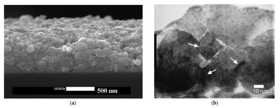
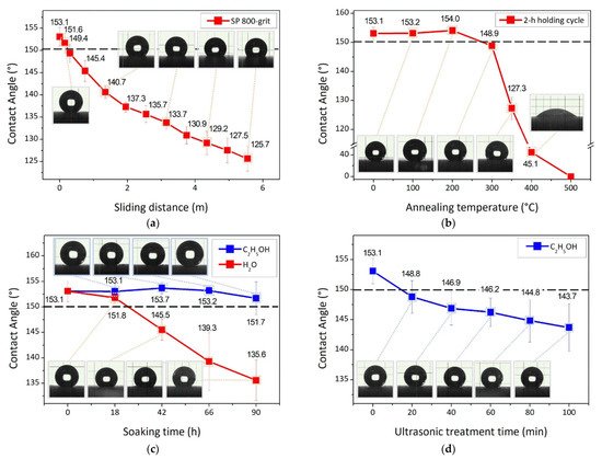
Figure 29. Wettability of SiO2–F coating sprayed on alumina substrate as a measure of contact angle after durability test being: (a) abrasive wear test on 800-grid sandpaper, (b) heat treatment in 2-h annealing cycles, (c) immersion in water and absolute alcohol and (d) ultrasonic bath treatment in absolute alcohol. The dashed line represents the superhydrophobic limit for CA being 150° [242].
Table 3 shows the main applications of ceramic coatings produced by LPCS.
Table 3. Selected applications of the LPCS ceramic coatings.
| Powder Material | Powder Preparation Method | Coating Application | Reference |
|---|---|---|---|
| TiO2 (various polymorphs) | Sol-gel | Photocatalyst | [240,241,283] |
| GaN | N/A | Photocatalyst | [284] |
| HA | Spray drying | Biomedical | [292] |
| WO3 | N/A | fuel cell electrodes, photoanodes in photoelectrochemical cells for water splitting | [295] |
| SiC | N/A | anti-oxidation at elevated temperatures | [298] |
| SiO2 | Sol-gel | hydrophobic surfaces | [242] |
This entry is adapted from the peer-reviewed paper 10.3390/coatings11091044
This entry is offline, you can click here to edit this entry!