In high-speed fluid dynamics, base pressure controls find many engineering applications, such as in the automobile and defense industries. Several studies have been reported on flow control with sudden expansion duct.
- flow control
- de Laval nozzle
- CD nozzle
- microjet
- supersonic flow
- CFD
- DOE
1. Introduction
In supersonic vehicles, the flow of exit from the rockets and missile engines has become a significant issue. It has been found that the loss of air inside the high-speed vehicle engines turns to increases the base drag. For example, a nozzle with sudden expansion ducts will form a recirculation zone, increasing base drag. When the base drag increases, the total amount of exit pressure will decrease, and this decrement will result in the loss of the forwarding force or thrust. Hence, many studies have reported controlling the high-speed flows as a passive and active control method. In a passive control method, the duct shape is modified with additional devices/shapes, such as ribs, cavities, cylinders, aerospikes, splitter plate, etc. In addition, researchers used different devices of flow formation, such as a nozzle as internal flow control and bluff body, non-circular cylinders, airfoil, and wings as external aerodynamics flow control. On the other hand, the active control of high-speed flow has been studied extensively over the last two decades. Researchers have used a high-speed nozzle with a sudden expansion duct and a microjet controller; a tiny hole in the base area is drilled to control the flow, which was found to be an excellent technique in a supersonic flow problem. Hence, this review is more focused on the active control approach, using a microjet in a CD nozzle.
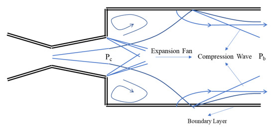
The abrupt expansion of the external compressible flow over the back of the projectiles and its association to the base pressure has long been the focus of researchers’ interest. The base drag, which accounts for a significant portion of the overall drag, is determined by the base pressure. Generally, the base pressure for a high-speed projectile is lower than the ambient pressure. The vast majority of the ballistics test data were supplied, leading us to presume that the base pressure ratio depends entirely on the flight Mach number. Compared to traditional ballistics testing processes, the experimental investigation of the internal flow apparatus provides several distinguishing benefits. A significant amount of air supply is lowered, which would generally be necessary for the wind tunnel test section to be large enough so that wall interference and other factors do not disrupt the model flow. Internal flows are free of stings and other support devices that are necessary for external flow investigations. The most significant benefit of the internal flow device is that static pressure and surface temperature measurements can be recorded as well as the entry to the expansion and the wake zone (Figure 1). These observations are crucial if the theoretical predictions are to be extensively investigated.
The sudden expansion problems in the subsonic and supersonic flow regimes are found in many applications. We discovered that previous researchers used a system to replicate high altitude conditions in jet and rocket engine test cells, jet discharge results in insufficient, sub-atmospheric discharge pressure. This was found by Khan et al. [1], who used microjets to control the sudden expansion flow (base pressure) from the CD nozzle as an active control method.
2. High-Speed Flow Development in Nozzle
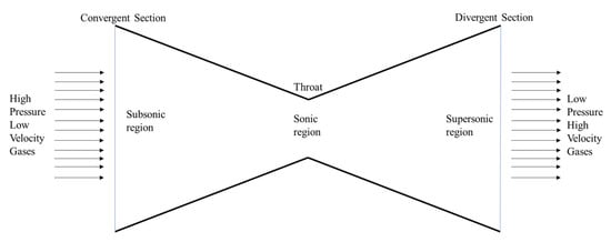
For supersonic flow development and investigations, a CD nozzle is utilized in most studies. A nozzle with no expanding part cannot produce supersonic air [3]; the flow is sonic at the throat; therefore, an asterisk denotes conditions at a sonic level. At the throat, the Mach number = 1, (V = a) and the throat area (a). Figure 2 illustrates a basic CD nozzle model [4] and the parameters with an asterisk are defined as critical values. If a high-pressure tank is connected to a pipe, then the velocity at the pipe exit changes depending on the backpressure. At any other region of the nozzle, the Mach number velocity and the local area can be derived by the continuity equation [5,6,7]. Even though it is possible to study one-dimensional flow behavior directly, it is only a particular case of two-dimensional flow. One of the known one-dimensional flow phenomena is the normal shock and formation of oblique shock waves. The occurrence of oblique shock waves in different flow fields occurs, such as flight at high Mach numbers, aircraft design, diffusers, and supersonic nozzles.
3. Passive Control Methods
It was observed that the high-speed flow controlled by the excitation of free shear-layer instabilities [42] uses localized arc filament plasma actuators in jets for different Mach numbers at a supersonic range. Focusing the aspect ratio of the nozzle and nozzle pressure ratio (NPR) with the Mach number variation, the elliptic jet control with limiting tab [43] was investigated and showed that each parameter is important to control the jet flows, similar to the overexpanded plug nozzle jet [44] controlled by the passive method. Additionally, some researchers used ventilated triangular tabs to control the jet [45], control the supersonic elliptic jet with ventilated tabs [46], and to measure the impact of the tab location relative to the nozzle exit on the shock structure of a supersonic jet [47].
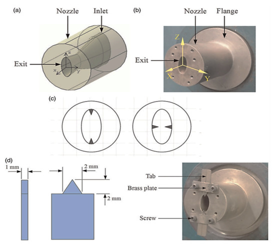
Khan et al. [48] experimentally investigated the effect of the extended cowl on the flow field of planar plug nozzles for two different Mach number ranges (1.8 and 2.2) to observe the influence of the cowl length for the pressure distribution. Manigandan and Vijayaraja [49] experimentally investigated the flow-field and acoustic characteristics of the elliptical throat in the CD nozzle. According to the findings, switching from an elliptical to a circular throat alters the shock cell architecture, resulting in a substantial shift in the scream amplitude, owing to wave weakening. The jet controlled for mixing the flow was experimentally studied by Khan et al. [50] for the enhancement of the supersonic twin-jet mixing by vortex generator to observe the effects and the behavior of the daughter streams. Similarly, an impinging plug nozzle jet using a vortex generator [51] was studied experimentally. Figure 4 shows the nozzle and tab details, CAD drawing (Figure 4 a), photographic view without tabs (Figure 4 b), schematic sketch of nozzle exits with triangular tabs along the major and minor axes (Figure 4 c), and triangular tab dimensions and the photograph of the nozzle with triangular tabs along the major axis (Figure 4 d).
The bulk of these noise reduction systems are referred to be passive since they cannot be switched off or changed while in flight and might result in performance losses. Penn State [56] is developing a fluid insert technique for supersonic jet noise reduction. The fluid insert method aims to reduce noise in low bypass ratio turbofans while having minimal impact on engine performance. The fluid inserts blast air into the diverging portion of the nozzle on demand, which may be turned off or adjusted depending on the flight regime. Although significant research has been conducted in the form of noise measurements and Reynolds-averaged Navier–Stokes (RANS) calculations to enhance the fluid insert technology [57,58], the reason why these inserts work is still not understood completely. The correlation of changes in the flow field with corresponding changes in the noise is inadequate, using only existing RANS data [59,60]. It was suggested that unstable scale-resolving simulations be used to obtain more insight into the flow field and to better understand noise reduction techniques [56]. Additionally, when properly structurally supported, acoustic reflectors of an adequate scale are a suitable noise reduction solution for the high-pressure venting typical of blowdown operations [61]. Due to disadvantages, such as delayed convergence and the complexity of the phase shift mechanism, a unique technique was used that does not use secondary path modeling [62] and the sensitivity of noise to system uncertainties [63]. Fluid inserts reduce the convection speed of wave packets in the jet shear layer, resulting in a reduced Mach wave radiation angle [64].
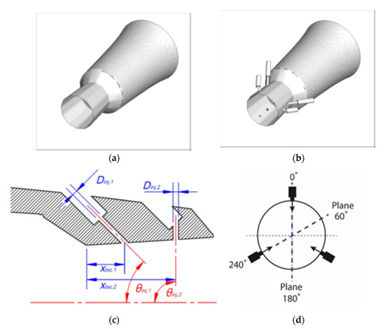
This interaction is discussed here with a focus on noise creation and reduction when a jet is parallel to or impinging on a solid wall. Various researchers have presented computational methods [65,66] with large-eddy simulations [67,68,69,70,71], high fidelity simulations [72] and 3D simulation [73]. The noise reduction of supersonic jets by nozzle trailing-edge changes was investigated experimentally [74], and hemispherical noise reduction reflectors on transonic jet flows [75] were conducted. Different injection sites, angles, and circumstances were also investigated, resulting in distinct acoustic behavior and flow-field changes [76]. Using steady fluidic injection, researchers conducted an empirical scaling analysis of supersonic jet control [77]. Aft and lateral wall inclinations for a cavity [78] supersonic cavity flow utilizing high-speed upstream injection [79] and cavity dynamics to the introduction of various storage configurations installed at different positions inside the cavity [80] were all numerically modeled for noise reduction. The employment of a single injector as a fluid insert helps break up the large-scale structures of the flow, according to direct cross-correlations of near-field data with far-field microphone signals [81]. Pipe-jet noise is reduced via geometric changes in the form of trailing edge castellations. The interaction between the streamwise vortices is determined by the number of castellations, which changes the sound generated [82]. Figure 5 shows the noise reduction configurations, which are adopted in the nozzle exit region, and represents the baseline nozzle (Figure 5 a), nozzle (Figure 5 b), schematic of a single fluid insert in the nozzle (Figure 5 c), and designation of different azimuthal planes for the 3FC-2FI nozzle (Figure 5 d).
4. Active Control Methods
The major consideration of this review work is to explore the active control methods of supersonic flows. Therefore, this section is split into the methodologies employed by the researchers: experimental, CFD, and soft computing approaches.
In summary, Khan et al., investigated the active control of the base pressure [1,15,82,83,84,85,99] in which they considered the differed Mach number at various supersonic flow ranges, such as Mach numbers 1.25, 1.30, 1.48, 1.6, 1.8 and 2.0 in [84,85]; 1.87, 2.2 and 2.58 in [15]; and 2.0, 2.5 and 3.0 in [82], respectively. The test area ratio was from 2.56, 3.24, 4.84, and 6.25; the NPR was from 3 to 9, and the duct length for L = 10D until 1D. More attention was given in the recent study to wall pressure distribution for different inertia levels, relief to the flow, NPR, and the L/D ratio [93,100,101,102,103,104,105,106,107]. After monitoring the flow from the active microjet control, it is also necessary to know whether the flow changes in the duct or not. Hence, recent findings have also shown that several studies are conducted with equivalent or variable Mach number and area ratios with the same NPR and L/D ratios. The majority of wall pressure flows were considered with varying the area ratio, such as 2.56 [93,100], 3.24 [101,102,108,109], 4.84 [103,104,105,110], and varying the Mach number for the same area ratio 2.56 with Mach 2 and 3 [106], 1.3. 1.9, and 2.4 [111] and for the area ratio 6.25 with Mach 1.1 and 1.5 [112] and 2.1 and 2.8 [113].
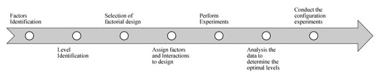
Researchers used the DOE principle based on the current problem and found that this could be an efficient way to achieve the base pressure control with an appropriate parameter. Therefore, to refine the base pressure control, the DOE technique was used. The impact of microjets on control was achieved to obtain base pressure differences of various parameters. The general DOE approach method can be seen in Figure 11 .
The experimental study was used for various parametric combinations using microjets to control the base pressure, using a CD nozzle. The data were used to refine the optimal mix of parameters employed to provide precise control of base pressure for improved performance with DOE [151]. A Taguchi design L 9-OA and variance analysis (ANOVA) was used to analyze the influence of nozzle parameters affecting the base pressure. Multiple linear regression models, confirmation checks, and linear regression equations were performed for accuracy in an optimization. The ANOVA method was also used to obtain the individual parameter's statistical significance on the total base pressure variability [152]. The observation on the control becomes effective for lower area ratio, compared to the higher area ratio with the aid of 15 arbitrary test cases; two linear regression model presentations were tested for their estimated accuracy [153]. To optimize the response surface methodology (RSM) of experimental data, non-linear regression models based on the central composite design (CCD) and box-Behnken design (BBD) were developed to simplify the input-output relationships [154]. The DOE with L 27-OA and ANOVA was used to determine the feedback (in percentage terms) of various process parameters and their correlations with and without control on the base pressure [155,156]. The optimum nozzle parameters were targeted, such as convergent angle, divergent angle, and the throat radius of the nozzle; the best values were assessed based on the flow parameters [157]. Jaimon et al. [158] used the DOE method to predict the suddenly expanded flow with and without microjets as an active control. To develop the linear model, they used a complete factorial design of the L 16 orthogonal array (OA). Using Taguchi’s L 27 orthogonal array, a regression analysis was made [159], and optimized results investigated the suitable parameters for base pressure control.
This entry is adapted from the peer-reviewed paper 10.3390/app11156899