Your browser does not fully support modern features. Please upgrade for a smoother experience.
Please note this is an old version of this entry, which may differ significantly from the current revision.
Subjects:
Engineering, Electrical & Electronic
Flexible antennas consist of a dielectric material (which works as the substrate) and a conductive material (which can be used as a radiating element and/or ground plane).
- metamaterials
- high-performance textiles
- wearable antenna
1. Introduction
Flexible substrates including organic substances, such as polymers, paper, plastics, textiles, and fabrics, have become increasingly important to enable increased flexibility in wearable sensors/antennas [1]. Flexible antennas consist of a dielectric material (which works as the substrate) and a conductive material (which can be used as a radiating element and/or ground plane). Pure metals, metals mixed with fabrics, and conductive inks [2] are examples of materials that can be used as conductive materials. Meanwhile, polymers such as foam, paper textile fabrics, plastics, and soft printed circuit boards (PCBs) are all common dielectric polymer materials. Other than dielectric polymers, extensive research has been conducted on conductive polymers. They are explored for various applications such as solar energy harvesting [3], tissue engineering [4], supercapacitor design [5,6,7], gas sensors [8], and immunosensors [9]. In particular, flexible conductive polymers were also proposed by [10,11]. However, in antenna designs, more concerns are directed to the dielectric of the antenna since the antenna performance is mainly determined by the electrical characteristic and the mechanical flexibility of the dielectric substrate. Recent developments in manufacturing techniques for flexible polymer antennas are appealing due to the low permittivity with low losses [12]. In flexible antenna designs, dielectric polymer materials which are commonly used as substrates are classified either as natural polymers (e.g., rubber, silk, wool) or synthetic/human-made polymers (e.g., polystyrene, polyvinylchloride, nylon) [1]. Textile structural composites (which are considered as natural materials) are versatile in terms of their exceptional physical and mechanical properties which can be adopted in particular engineering applications to meet the desired requirements [13].
Ultrawideband (UWB) technology has triggered enormous research attention in wireless communications, especially after the allocation of the unlicensed frequency band (3.1 to 10.6 GHz) by the Federal Communications Commission (FCC) in 2002 [14]. A UWB antenna has the capability of providing high-speed data transmission with low-power spectral densities compared to conventional wireless communication systems within short distances. The application of UWB has been expanded into the wireless body area network (WBAN) domain based on the IEEE 802.15.6 WBAN standard [15,16]. Recent technological developments have resulted in compact and smart biomedical sensors/antennas for implementation on the human body. These antennas and sensors are most ideal for implementation in WBAN-type networks, as they are useful in sectors such as wearable computing, health monitoring, rescue systems, and patient tracking [17,18]. These applications require wireless devices to be placed close to the human body, which demands antennas and sensors to be developed using flexible materials. To prolong their usage near or on the body and, at the same time, ensure the safety and comfort of the user, they are best to be integrated onto clothing. Recently, conductive textiles have been introduced commercially, spurring the design of antennas for WBAN using textiles [16].
Sensors and smart devices have been the subject of extensive research over the past decade, with the goal of making them more easily integrated onto the human body [19]. Fabrics have been used as a natural and comfortable substrate for wearable electronic devices. Fabrics can now contain electrical functionality due to miniaturization of electronic components and innovative technologies [20]. There has been a lot of recent research on cloth fabrics, including sewn textiles, embroidered textiles, nonwoven textiles, knitted fabrics, woven fabrics, printed fabrics, braiding, laminated fabrics, spinning, and chemically treated fabrics [21]. Developing modern textile-based sensors has become a substantial undertaking in recent years, with numerous studies focusing on applications such as athletic training [22], emergency rescue and law enforcement [23], fitness monitoring [24], and other fields.
Metamaterials (MTMs) are artificial composite structures with exotic electromagnetic properties which can be used for potential groundbreaking applications (e.g., in antenna design, subwavelength imaging) [25]. Consequently, MTMs are suitable to be applied to improve WBAN antennas in terms of gain, radiation patterns, bandwidth (BW), and size compactness [26,27,28]. The characteristics of MTMs can be single negative (SNG) or double negative (DNG) based on the dielectric permittivity (ε) or magnetic permeability (μ). For SNG MTMs, either ε or μ can be negative, and for DNG MTMs, both ε and μ are negative. For SNG MTMs, if ε is negative, they are called epsilon-negative (ENG) MTMs, and if μ is negative, they are called mu-negative (MNG) MTMs [17,29]. Furthermore, the refractive index of a material depends on the ε and μ, which defines the extent of reflection and refraction [30]. However, the near-zero refractive index (NZRI) property can enhance the gain, as reported in [31]. Several metamaterial structures have been proposed in terms of complementary split-ring resonators (CSRR) [26,32], split-ring resonators (SRRs) [33], planar patterns, and capacitance-loaded strips (CLSs) [29]. Some other MTM structures such as electromagnetic bandgaps (EBGs) and artificial magnetic conductors (AMCs) were discussed in [27]. Such metamaterial-based UWB antennas have been reported in the literature with proven antenna performance enhancements [27,28]. In [34], MTMs were loaded into UWB wearable antennas for non-invasive skin cancer detection. Likewise, in [35], the proposed MTM UWB antenna was used for breast cancer detection. Despite the different designs, antennas for wearable applications should be compact, low cost, lightweight, and able to be integrated into circuits with ease [28]. When constructing metamaterials for metamaterial-enhanced devices, it is crucial to take into consideration the fabrication difficulty. Therefore, when developing textile-based metamaterials, extra care should be taken in each design phase [21,36].
2. Specific
Figure 9 depicts the evolution process of the conventional antenna design in this study. In the first stage, as shown in Figure 9a, a full grounded patch with a combination of rectangular and half elliptical-shaped patches produces relatively narrow frequency bands, as shown in Figure 9b. In order to achieve a wider impedance bandwidth, the ground plane of the antenna was modified, as illustrated in the second stage of Figure 9b. From Figure 9b, it can be seen that the second stage has a wider impedance bandwidth compared to the first stage. Furthermore, in the third stage, a 0.4 mm gap was chosen to avoid a short circuit between the 50 Ω connector and the feedline of the planar monopole antenna. The truncation at the ground plane improved the impedance bandwidth slightly, where S11 resulted in being lower than −10 dB, showing over 2.33–2.6 GHz, and 8.52–12.3 GHz, which means FBW = 47% at the frequencies of interest. It can be noticed that the attained impedance bandwidth does not cover the complete UWB band allocated by the FCC. However, integration of the proposed MTMUCA with the conventional antenna can improve the overall performance. The related evidence can be found in the following results and discussion.
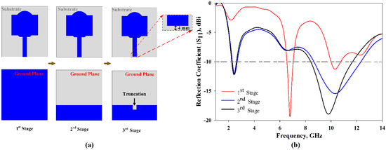
Figure 9. Evolution process of the conventional antenna in this study. (a) Evolution steps; (b) S11 results.
The fabricated prototype was used to validate this work, which is shown in Figure 10. The dielectric polymer material (viscose-wool felt) and conductive material (Shieldit SuperTM) of the prototype were dimensioned by a laser cutting machine as a part of the fabrication process. A great deal of study has already been carried out on a variety of materials that have characteristics that render them appropriate for use as a substrate for conductive materials for antennas, conductive threads [52], conductive polymers [53], and conductive textiles [54]. However, in this study, viscose-wool felt was adopted since it provides easier fabrication with sufficient flexibility and enables strong adhesion with the conductive textile Shieldit SuperTM. S11 measurement was performed using an Agilent E5071C Network Analyser (Agilent Technologies, Bayan Lepas, Penang, Malaysia) to ensure the simulated findings are accurate. The comparison of the proposed antenna between the simulated and measured S11 illustrated in Figure 11 indicates a good agreement. The simulation indicates a 10 dB impedance bandwidth from 2.55 to 15 GHz, which corresponds to an FBW of 142%. The measurement results indicate that this range is from 2.63 to 14.57 GHz, with an FBW of 138.84%. On the other hand, the antenna without the MTMUCA in Figure 9b (third iteration) shows a simulated FBW of 47%. Although the conventional antenna (considering the third iteration in Figure 9) does not work within the FCC region, by utilizing the unique characteristics of the metamaterial, the antenna performance could be enhanced. By utilizing the MTM on the conventional antenna, the antenna element’s radiation efficiency, gain, and overall performance can be improved.
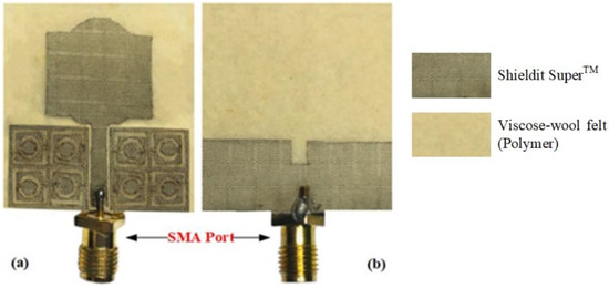
Figure 10. Prototype of the designed antenna: (a) front view, and (b) rear view.
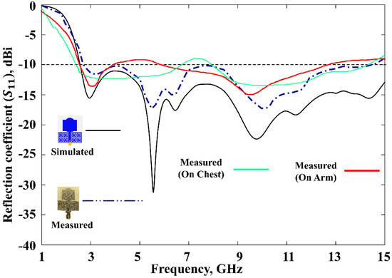
Figure 11. Reflection coefficients of the proposed antenna.
To rigorously analyze the performance of the proposed MTM-driven antenna prototype, body evaluation was further carried out with the help of a male volunteer (with a height of 1.72 m and weight of 84 kg), as shown in Figure 12. The prototype antenna was placed on two different places on the body (chest and arm). The related S11 results are presented in Figure 11, which indicate an excellent performance of the proposed antenna for on-body application. It can be noted that a 6 dB reflection coefficient is frequently used in the manufacturer’s specification, as reported in [55,56]; hence, the obtained performance is sufficient for practical application.
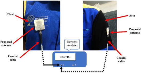
Figure 12. On-body measurement setup.
Figure 13 shows the antenna gain and total efficiency over the frequency. In simulations, an average realized gain of 3.3 dBi was achieved with the MTMUCA, whereas it was 2.7 dBi without the MTMUCA. A maximum gain of 4.83 dBi and 3.64 dBi could be obtained with the proposed antenna with and without the MTMUCA, respectively. On the other hand, the average measured gain of the proposed antenna is 3.04 dBi, and the maximum peak gain is 4.4 dBi. The maximum total efficiency achieved is 87% and 79.5% for the antenna with and without MTMUCA implementation, respectively, in simulations. The attainable average total efficiency of the proposed antenna is approximately 73%, whereas the antenna without the MTM indicated levels of around 69%. The measurements show a maximum total efficiency of 80%, and the average efficiency is 68.2%, for the proposed integrated antenna.
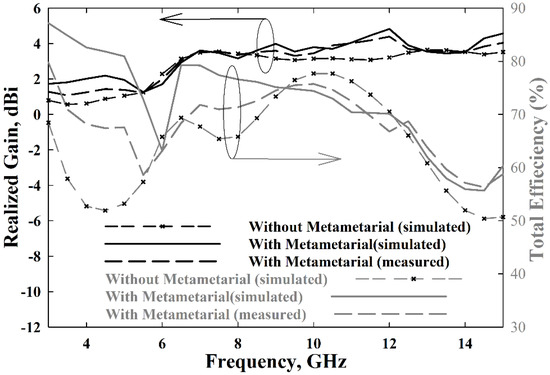
Figure 13. The proposed antenna’s realized gain and radiation efficiency.
Figure 14 illustrates the radiation characteristics of the proposed antenna. The simulated and measured radiation patterns of the E-plane (yz-plane) and H-plane (xz-plane) were performed at four different frequencies, i.e., 3 GHz, 6.5 GHz, 10 GHz, and 12 GHz, indicating very good agreement. An omnidirectional radiation pattern can be observed at 3 GHz. Meanwhile, at 6.5 GHz, 10 GHz, and 12 GHz, an omnidirectional pattern can be seen in the H-plane, whereas the E-plane shows a bidirectional radiation pattern. Slight discrepancies between the simulations and measurements can be observed due to fabrication inaccuracies.
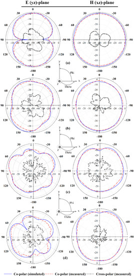
Figure 14. Radiation patterns of the proposed antenna at: (a) 3 GHz, (b) 6.5 GHz, (c) 10 GHz, and (d) 12 GHz.
This entry is adapted from the peer-reviewed paper 10.3390/polym13162819
This entry is offline, you can click here to edit this entry!