1. Introduction
Power-over-fiber (PWoF) has a considerable mature technology, and its research and development have been conducted since the late 1970s. In those days, the cost of PWoF was much higher than those of conventional power lines, such as copper wires, and the performance of related components, such as light sources and photovoltaic power converters (PPCs), had to be improved considerably. However, approximately 40 years have passed since the introduction of PWoF technologies. Its key components, including optical fibers, have undergone significant developments; consequently, PWoF has become more sophisticated and is now being developed into various application technologies.
Owing to the development of PWoF technologies, features that are not available in conventional power supply systems are now realized, e.g., lightweightness, corrosion resistance, and robustness to electromagnetic interference (EMI) and electric sparks. Consequently, the application field of PWoF has expanded significantly. In particular, optical fibers, which are widely used as high-speed communication lines, are expected to significantly affect future infrastructure facilities by enabling telecommunication, sensing, and power transmission.
The features of PWoF and its key components are presented herein. Moreover, recent advancement in PWoF technologies based on their latest results is introduced.
2. Features of PWoF
PWoF systems comprise three key components: light sources, optical fibers, and PPCs. The optical power from a light source propagates through an optical fiber and is converted into electrical power via a PPC. The converted power can be used to drive electronic devices in remote units. In this system, the delivered electric power and power transmission efficiency are the two important factors. The former is an indicator of the amount of transmittable electric power, whereas the latter is an indicator of the efficiency of electric power transmission. To satisfy these requirements, the performances of the key components are critical. In addition, PWoF systems will be more attractive if a single optical fiber can transmit data signals for sensors and telecommunications simultaneously. The features of each PWoF component are described below.
2.1. Light Sources
High-power laser diodes (HPLDs) and fiber lasers are often used as light sources for PWoF systems. Fiber-pigtailed HPLDs are typically used as commercial products from the view point of connectivity with optical fibers. Regarding HPLDs, their operating wavelength and output power depend significantly on the composition of the material. In particular, 808, 830, and 980 nm are the major wavelength bands in PWoF systems. In fiber-pigtailed HPLDs, to inject the output lights from multiple LD chips into an optical fiber, an optical fiber with a larger core diameter is advantageous in order to inject more power into the optical fiber. For fiber-pigtailed HPLDs exceeding 10 W, it becomes difficult to inject high-power light into conventional small core. For optical fibers with an outer diameter of 125 μm, which is typically used in optical fiber communications, the output power is generally limited to 40 W or less. The electrical-to-optical (E/O) conversion efficiency of HPLDs, which depends on the composition of the material, is generally between 30% and 50%.
Regarding high-power fiber lasers, their operating wavelength and output power depend significantly on the configuration of laser cavity. In particular, since Raman fiber lasers enable us to control the oscillation wavelength by utilizing stimulated Raman scattering (SRS) in the cavity, it is possible to provide high-power lasers in the 1480 nm and 1550 nm bands. In addition, since the cavity composes an optical fiber, it can be easily connected to an optical fiber for transmission. On the other hand, fiber lasers give rise to mode partition noise due to multimode oscillation, which degrades signal quality when transmitted simultaneously with data signals.
2.2. Optical Fibers and Connectors
Conventional silica optical fibers have a simple waveguide structure comprising a core and a cladding; however, even in PWoF, the difference in the structure results in a significant difference in performance. In particular, when high-power light is injected into an optical fiber with a small core, nonlinear effects, such as SRS and stimulated Brillouin scattering, occur in the core, which can cause significant signal degradation in data signals when transmitted simultaneously with data signals. The development of optical fiber communications in recent years has enabled the development of various optical fibers. The structures of each optical fiber and its features when used in PWoF are shown below.
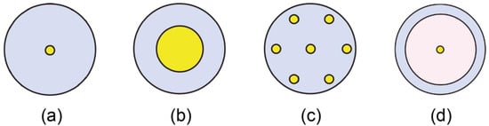
Figure 1 shows the cross sections of various types of optical fibers for PWoF. Single-mode fibers (SMFs) are still widely used as a highly versatile optical fiber. One of its features is that the core diameter through which the optical signal propagates is as small as 8–10 μm; therefore, the optical signal is transmitted in a single propagation mode. Consequently, bandwidth limitations are not applicable owing to the propagation delay between modes, and broadband signal transmission is possible. By contrast, high-power feed light transmission for PWoF is difficult to achieve owing to the extremely high-power density, which gives rise to critical damage to the fiber such as fiber fuse. Multimode fibers (MMFs) have a larger core diameter than SMFs and are advantageous for high-power transmission. However, MMFs have many propagation modes, thereby resulting in transmission bandwidth limitations owing to modal propagation delay. Multi-core fibers (MCFs) exhibit structures comprising multiple cores, as shown in
Figure 1c, and have high data capacity that corresponds to the number of cores. In PWoF, although the diameter of the core is small, optical signals and feed light can be transmitted simultaneously using multiple cores. Double-clad fibers (DCFs) has been primarily used as a gain medium for high-power lasers and optical amplifiers. By injecting optical signals to be amplified into the central small-diameter core and pumping light for optical amplification into the outer inner cladding, a DCF can be operated as an optical amplifier with high gain. By contrast, in PWoF, by injecting optical signals into the central, rare-earth undoped core and by feeding light into the large-diameter inner cladding, broadband transmission for optical signals and high-power transmission for feed light can be realized simultaneously. In
Section 3, the actual applications of PWoF systems using these fibers are described comprehensively.
Figure 1. Cross sections of various types of optical fibers for PWoF. (a) Single-mode fibers (SMFs), (b) Multimode fibers (MMFs), (c) Multicore fibers (MCFs), and (d) Double-clad fibers (DCFs).
In addition to the abovementioned fibers, hollow-core fibers (HCFs) are attractive optical fibers that have recently garnered significant attention. This fiber enables the transmission of optical signals by confining them in a hollow region corresponding to the core. Because optical signals propagate in air, the propagation speed is expected to be increased to approximately 1.5 times faster than those of silica-core optical fibers such as SMFs, MMFs, MCFs, and DCFs. This will be advantageous for optical fiber transmission in a 5th Generation (5G) Mobile Communication System, where ultra-low latency signal transmission is required. Moreover, because the core of HCPs is air, it is highly resistant to the input optical power, and is less susceptible to various phenomena that occur in silica-core optical fibers, such as chromatic dispersion, nonlinear effects, and modal noise in the fiber. By contrast, HCFs exhibit a complicated cross-sectional structure that can efficiently confine light in its hollow core; currently, long-distance spinning in HCFs is difficult to achieve as many issues remain to be solved before the practical stage can be reached. As for PWoF technologies using other optical fibers, simultaneous signal and power transmission experiments using a large-core microstructure optical fiber and a step-index plastic optical fiber have also been reported recently.
As feed light power increases, optical connectors become more important. In particular, an SMF with a small core has an extremely high power density, which causes the optical fiber connections to be damaged easily and limits the transferable optical power. A practical approach for solving this problem is to use an expanded beam connection based on ferrules terminated with graded-index fibers (the core diameter of 25 or 50 μm); this method offers the advantage of superior high-power connection performance of up to 16 W in terms of insertion and return losses. Another alternative is to splice the fibers. In PWoF, both higher power tolerance and lower connection loss are to be achieved.
2.3. PPCs
PPCs are essential elements in PWoF, and enable us to convert input optical power into electrical power. The PPC characteristics significantly affect the performances of optical wireless and fiber power transmission systems. For PWoF applications, PPCs must be of a compact size to match the beam diameter output from the optical fiber end-face. In addition, unlike solar cells, PPCs convert optical power from a laser source into electric power; hence, it exhibits conversion characteristics specific to certain wavelengths, which depend significantly on the composition material. PPCs for various wavelength bands can be fabricated by selecting the appropriate composition materials. Next, PPCs that are currently being widely researched and developed extensively for each wavelength band are introduced.
Most PPCs were developed in the 800–860 nm wavelength band, and many PPCs with high conversion efficiencies (CEs) and high performances have been reported. Owing to the abundance of high-performance HPLDs in this wavelength band, the latter is well known as a promising wavelength band of feed light sources for PWoF. In the latest research result, a PPC that achieved a conversion efficiency of 68.9% at 858 nm by photon recycling and optical resonance has been reported. In the 960–980-nm wavelength band, many PPCs have also been reported as well because high-performance and low-cost HPLDs can be fabricated there. More recently, PPCs that support longer wavelengths, such as 1310 nm and 1550 nm, have been developed. In particular, the 1550-nm band is garnering significant attention from the viewpoint of eye safety, and it is an advantageous wavelength band for both PWoF and optical wireless power transmission.
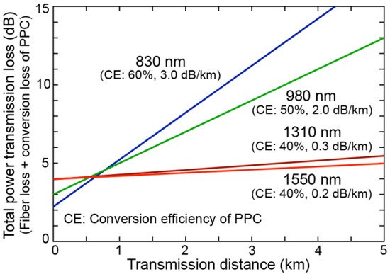
When considering the power transmission efficiency of an entire PWoF system, the wavelength of the feed light used has a significant affect, not only on the CE of the PPC, but also on the transmission loss of the optical fiber. Figure 2 shows an example of the relationship between the transmission distance and total power transmission loss determined by the sum of the fiber transmission loss and conversion loss of the PPC. In this regard, the loss at a transmission distance of 0 km indicates the conversion loss determined by the CE of the PPCs at each wavelength, and the slope of each line indicates the transmission loss of the fiber. The CE at each wavelength is the average CE of the PPCs reported in recent studies. For the transmission loss, we used the values of conventional SMFs. It should be noted that this total power transmission loss does not include the E/O conversion loss of the feed light sources. As shown in Figure 2, because a shorter wavelength feed light yields a higher CE, a lower power transmission loss will be achieved when the transmission distance is short. However, as the transmission distance increases, the fiber transmission loss becomes more dominant than the conversion loss of the PPCs, and a longer-wavelength feed light offers a lower power transmission loss. This indicates the importance of transmission distance in determining the feed light wavelength. Hence, the power transmission efficiency depends significantly on both the transmission distance and the feed light wavelength. Meanwhile, the transmitted optical power is also determined by the available output power of the light sources and the available input power of the PPCs. To develop a more efficient and higher power PWoF system, all of the abovementioned factors must be considered.
Figure 2. Example of transmission distance versus transmission and conversion losses for various feed light wavelengths.
3. Optically Powered Sensor Systems
In PWoF, optically powered sensor systems using optical fibers are the most versatile application technology. In general, sensors can be driven by a small amount of electric power, and the information obtained by the sensors can be transmitted by an optical fiber. In particular, PWoF is highly valuable in places where optical fibers can be utilized as non-conductive power lines.
3.1. Rotor Blade Monitoring Systems
Wind energy is an attractive renewable energy source, and wind turbines are used to exploit the potential of wind energy. It is essential to monitor the blade conditions of wind turbine rotors. However, conventional electronic sensors can be damaged by lightning strikes. Klamouris, C. et al. reported an optically powered rotor blade condition monitoring system as a lightning-safe system.
3.2. Current and Voltage Sensors
In future electric power networks, smart grid sensors will be crucial in providing real-time monitoring, protection, and control to the networks; however, they must be operated in a high-voltage environment. By contrast, because optical fibers are fabricated using non-conductive materials, the immunity to EMI is beneficial not only for measuring currents and voltages, but also for transmitting measured signals without quality degradation in high-voltage environments. In this regard, Bassan F. R. et al. reported an optically powered smart sensor system for electric power networks.
3.3. Other Sensor Applications
In addition, various other sensor applications have recently been reported. For example, since Internet of Things (IoT) sensors require power and transmission of sensor information, PWoF is a very effective way to simplify the configuration of the system. Underwater power transmission using cooper cables poses the risk of electrical leakage. However, this can be avoided by using optical fibers, and underwater sensors by PWoF for seafloor observatories have also been reported. PWoF also plays an important role in hazardous environments such as laboratories facilities where flammable materials are used and stored in order to avoid sparks and chemical affections of copper power line cables. A PWoF experimental demonstration to drive the sensors for such an environment has been reported.
4. Optically Powered Remote Antenna Units
Electric power is required in telecommunication systems. Therefore, the use of optical fiber, as both a telecommunication line and a power line, is attractive in these systems. However, because telecommunication devices and equipment require high electric power, any PWoF technologies that can deliver much higher electric power than sensor applications are described.
4.1. Remote Antenna Units for Mobile Communications
Owing to the rapid development of mobile communications, a large number of remote antenna units (RAUs) and their fiber connections are necessitated in the near future. In current mobile communication networks, the electric power required to drive RAUs is generally supplied by nearby commercial power lines. However, if the power with mobile data can be transmitted using a single optical fiber to an RAU, then the construction of a simple RAU system that does not require electrical work will be enabled, and the RAU will be extremely easy to install and operate. However, the power required to drive a small-cell RAU exceeds 10 W, which is much higher than the power that can be transmittable via conventional PWoF technologies. Hence, Matsuura, M. et al. reported a high-power PWoF system using a DCF, as shown in Fig. 1(d), to drive an RAU by increasing the core area for transmitting the feed light by more than 200 times compared with SMFs.
4.2. Optical-to-Radio Converter Module
In simple RAUs for small cells, the key components are the photo-diode (PD) and electrical amplifier. Umezawa T. et al. reported an optically powered optical-to-radio converter (ORC) module, which comprised a broadband PD and an electrical amplifier, based on an MCF, as shown in Fig. 1(c).
4.3. Microwave Amplifiers for Radio Stations
Microwave radio communication system is useful for monitoring and controlling electric power grid facilities. In such a system, a parabola antenna for line-of-sight communications is placed at the top of radio towers and connected to a radio station building via a conductive metal waveguide. However, if the radio towers are struck by strong lightning, then the electrical equipment in the radio station building will be damaged severely. Hence, Ikeda, K. et al. proposed a system configuration using optical fibers instead of conductive metal waveguides in order to protect the equipment from lightning. In that study, they reported a newly developed, optically powered microwave amplifier that provides applicable transmitting RF power.
This entry is adapted from the peer-reviewed paper 10.3390/photonics8080335