Levulinic acid (LA) is considered as one of the “Top 10” building blocks for future bio-refineries as proposed by the US Department of Energy. It is one of the most important platform molecules for the production of fine chemicals and fuels based on its compatibility with existing processes, market economics, and industrial ability to serve as a platform for the synthesis of important derivatives. Hydrogenation of LA to produce γ-valerolactone (GVL) is an active area of research due to the potential of GVL to be used as a biofuel in its own right and for its subsequent transformation into hydrocarbon fuels. This paper contains a new design for a simple, cost effective, and safe hydrogenation reactor for the transformation of levulinic acid to γ-valerolactone (GVL) by utilizing high boiling point organic fluid. The hydrogenation reactor is composed of a heating source—organic fluid (called “DOWTHERM A” or “thermex”) and the catalytic reactor. The advantages of high boiling temperature fluids, along with advances in hydrocracking and reforming technologies driven by the oil and gas industries, make the organic concept more suitable and safer (water coming in contact with liquid metal is well understood in the metallurgical industry to be a steam explosion hazard) for heating the hydrogenation reactor. COMSOL multi-physics software version 4.3b was applied in this work and simultaneously solves the continuity, Navier-Stokes (fluid flow), energy (heat transfer), and diffusion with chemical reaction kinetics equations. It was shown that the heat flux supplied by the DOWTHERM A organic fluid could provide the necessary heat flux required for maintaining the hydrogenation process. It was found that the mass fractions of hydrogen and levulinic acid decreased along the reactor axis. The GVL mass fraction increased along the reactor axis.
- bio-refinery
- levulinic acid (LA)
- hydrogenation reactor
- γ-valerolactone (GVL)
- alternative fuels
- CFD
- diphenyl mixture
- Navier-Stokes equation
- energy equation
- process simulation
- catalysis
- kinetics
1. Introduction
The utilization of biomass for the production of fuel and chemicals has become an important research topic because of the growing concerns regarding the depletion of fossil carbon reserves and the environmental impact (such as air pollution) of our continued dependence on these resources [1]. Levulinic acid (LA) is ranked as one of the “Top 10” building blocks for future bio-refineries as proposed by the US Department of Energy [2]. It is considered as one of the most important platform molecules for the production of fine chemicals and fuels [3] based on its compatibility with existing processes, market economics, and industrial ability to serve as a platform for the synthesis of important derivatives. Hydrogenation of LA to produce γ-valerolactone (GVL) is an active area of research due to the potential of GVL to be used as a biofuel in its subsequent transformation into hydrocarbon fuels [4]. GVL is considered as a sustainable liquid since it is renewable [5]. It has several very attractive physical and chemical properties [6]. Its vapor pressure is remarkably low, even at elevated temperatures and it does not hydrolyze at neutral pH. GVL is a safe material for large-scale use and can be utilized for the production of energy by adding it to gasoline [5]. Bereczky et al. showed that GVL significantly reduced the exhaust concentration of CO, unburned fuel, and smoke. The smoke reduction was particularly notable in light of the very recent suggestion that black carbon was the second most important greenhouse gas in the atmosphere next to carbon dioxide [7]. Licursi et al. [8] have studied and optimized cascade strategy for the catalytic valorization of levulinic acid. Their study has been carried out applying water as the only reaction solvent and heterogeneous commercial catalytic systems, which are more economical, available, and reproducible. Figure 1 shows the conversion processes of LA to a GVL and GVL to 2-Butanol and 2-Pentanol biofuels.
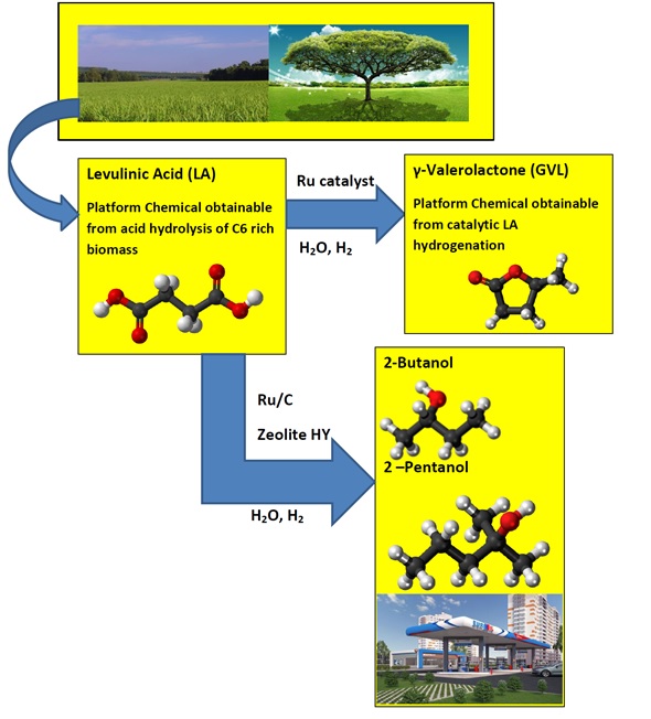
Figure 1. Conversion of levulinic acid to GVL and levulinic acid to 2-Butanol and 2-Pentanol.
1.1. GVL Production Process Catalysts
The hydrogenation of LA to GVL has been described by using both homogeneous and heterogeneous catalysts [9]. Filiz et al. [10] studied the catalytic hydrogenation of LA over zirconia supported ruthenium catalysts. They prepared four different Ru/ZrO2 catalysts with different pre-treatments and used different zirconium supports. They discovered that one of the catalysts produced a yield of more than 99% of GVL under mild conditions. This catalyst was also robust and could be recycled at least four times without any loss in activity or selectivity. It was shown that the activity can be attributed to the presence of small ruthenium particles together with acidic sites on the catalyst [10]. Figure 2 shows the schematic of the hydrogenation reactor of LA to GVL.
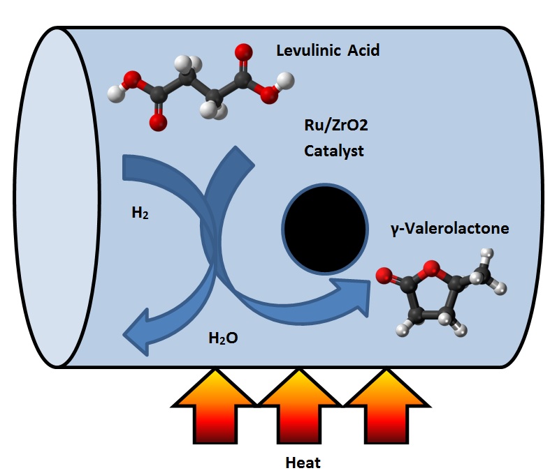
Figure 2. Schematic of the conversion process of levulinic acid (LA) to γ-valerolactone (GVL).
Ftouni et al. [11] compared the stability of different supported Ru-based catalysts under typical LA hydrogenation conditions in dioxane. It was shown that Ru/ZrO2 performed better than Ru/C and Ru/TiO2. The former catalyst materials displayed high activity, selectivity, and stability upon repetitive recycling. The hydrogenation reaction was studied at the hydrogen pressure of 30 bar and temperature of 423 K in dioxane as the solvent. All catalysts showed excellent yields of GVL when used fresh, but only the Ru/ZrO2 catalyst could maintain these high yields upon multiple recycling. The widely used Ru/TiO2 catalyst already showed quick signs of deactivation after the first catalytic test. The partial deactivation was due to the partial coverage of the Ru nanoparticles. In contrast, the zirconia support displayed high morphological and structural stability even after five recycling tests. In the fresh Ru/ZrO2 catalyst, Ru was found to be fully atomically dispersed on the fresh catalyst even at 1 wt % Ru loading, with some genesis of Ru nanoparticles being observed upon recycling. Further studies with the Ru/ZrO2 catalyst showed that dioxane could be readily replaced by more benign solvents including GVL itself. The addition of water promotes the selective hydrogenation reaction.
1.2. CFD Simulations of Biofuel Production
Wensel et al. [12] performed a computational fluid dynamics (CFD) simulation on the bio-refinery process for succinic acid and co-product. The finite volume method (FVM) technique was employed in the CFD simulation. The simulation included kinetic, stoichiometric, mass, and energy balance equations in order to simulate the effects of inlet temperature impeller speed, diameter, and spacing, inlet temperature, and fermentor volume on the fermentor cooling jacket heat transfer area. Predicted dissolved carbon dioxide concentrations in the fermentor had good agreement with those reported in the literature. The effects of the microfiltration recirculation rate, microfiltration stage numbers, and absorber sorbent particle diameter on the dimensional requirements and power consumption have also been considered. Yields and estimated volume and area requirements for the units of operation were obtained for the baseline process. Their work represents the first reported industrial-scale bio-succinic acid process model. Gorshkova et al. [13] performed a three phase CFD model for trickle bed reactors. Their model was extended to include reactions, mass transfer, and heat transfer. The stationary gas and liquid inside the porous particles were modeled separately from the bulk gas and liquid phases flowing outside the particles with convective and diffusive mass transfer between the inner and outer fluids. It was assumed that the catalytic reactions took place inside the catalyst particles. The process modeled in this work was the hydrogenation of octane (C8H16) in a Ni/Al2O3 reactor. The reaction is highly exothermic, resulting in the evaporation and condensation of the components. All sub models were implemented in Fluent software (version 12.1). Numerical tests were carried out to show that the CFD model allows for the investigation of local variations in the reactor, which are caused, for example, by bed drying or the effects of irregular liquid feed.
2. Results and Conclusions
A new design for a hydrogenation catalytic reactor to transform levulinic acid to γ-valerolactone (GVL) by using high boiling point organic fluids is proposed. The hydrogenation reactor is made of the catalyst bed material. It was assumed that the radius of the reactor was 0.05 m and the height of the reactor was 0.4 m. The hydrogenation chemical reaction occurred inside the catalytic reactor where the heat was supplied through the organic fluid to drive the endothermic reaction system. The heat flux was supplied at the inner and outer radius of the reactor. Levulinc acid and hydrogen were mixed in stoichiometric amounts and entered through the inlet of the hydrogenation reactor. This model investigates the hydrogenation of LA to GVL. COMSOL multi-physics software version 4.3b has been applied in this work and solves simultaneously the continuity, Navier-Stokes (fluid flow), energy (heat transfer), and diffusion with chemical reaction kinetics equations. The numerical results has been obtained for a heat flux of 2730 (W/m²) . It is assumed that the temperature of the reactants entering the hydrogenation reactor was 200 °C. Figure 3 shows the 3D temperature field inside the hydrogenation reactor.
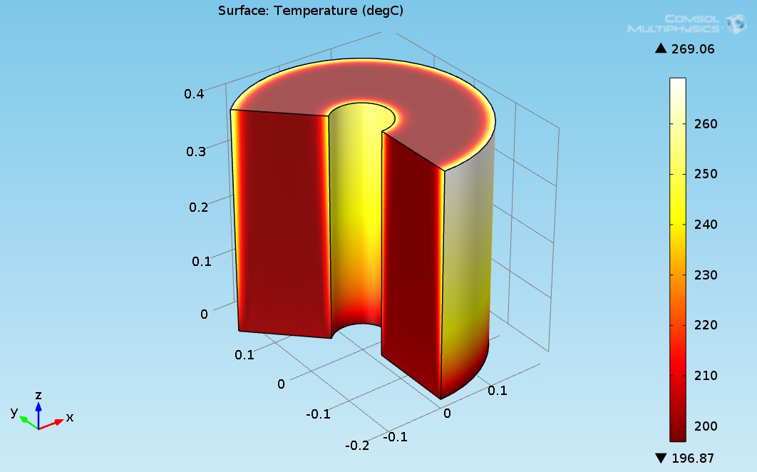
Figure 3. 3D plot of the hydrogenation reactor temperature field.
As seen in Figure 1, the temperature at the bottom section of the reformer is higher than the temperature at the upper side. This is due to two reasons: first, the endothermic reactions absorb the heat, and second, the thermal conductivity of the solution (levulinic acid and hydrogen) has a lower value. The temperature at the internal and external surfaces of the reactor was much higher than the temperature inside the bulk of the reactor, which is because they are exposed to heat supplied by organic fluid. The lower thermal conductivity led to a higher temperature gradient across the radial axis of the reactor. Figure 4 shows the 3D levulinic acid concentration field inside the hydrogenation reactor.
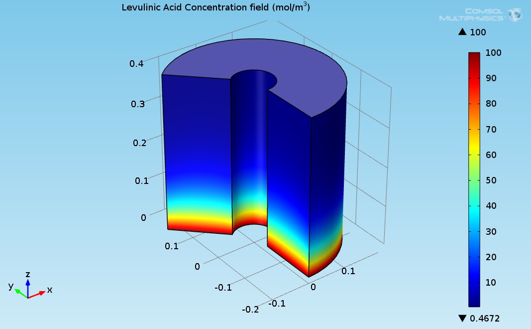 Figure 4. 3D plot of the levulinic acid (LA) concentration field.
Figure 5 indicates that the LA almost converted completely (100% conversion). Figure 3 shows the 3D GVL concentration field inside the hydrogenation reactor.
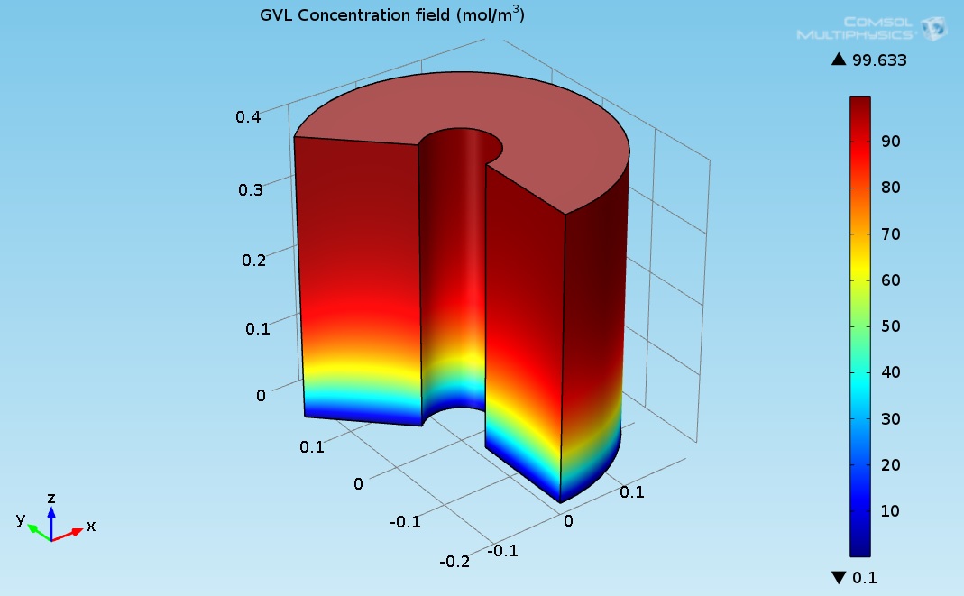
Figure 5. 3D plot of the γ-Valerolactone (GVL) concentration field.
Figure 3 indicates that the LA almost transformed completely to γ-valerolactone (GVL). The concentration of GVL at the top of the hydrogenation reactor had the highest values.The heat carried by the DOWTHERM A and supplied to the hydrogenation reactor can be produced by using solar energy or by using other heat sources such as a furnace burner or solar power station. The Hydrogen required for the hydrogenation reaction can be produced by using Methane Steam Reforming System. Figure 6 shows proposed GVL production system.
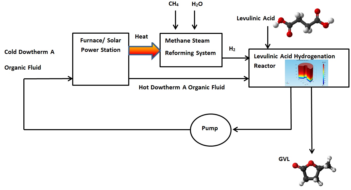
Figure 6. Proposed γ-Valerolactone (GVL) production system.
A computational model for the simulation of GVL burner was developed by using Fire Dynamics Simulator software (FDS) version 5.0. FDS simulation can provide much detailed information on the GVL burner, including the local and transient gas velocity, gas temperature, species concentration, solid wall temperature, fuel burning rate, radiative heat flux, convective heat flux and HRR. The temperature field at t = 42.1 s is shown in Figure 7.
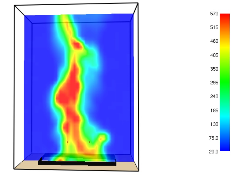
Figure 7. Temperature field (°C) inside the burner at t = 42.1 s.
The maximal temperature of the GVL flame obtained at time = 42.1 s approaches to 570 °C.
The model is described in detail in the following paper: https://doi.org/10.3390/chemengineering3020032
References
- Jones, D.R.; Iqbal, S.; Thomas, L.; Ishikawa, S.; Reece, C.; Miedziak, P.J.; Morgan, D.J.; Bartley, J.K.; Willock, D.J.; Ueda, W; et al. xNi–yCu–ZrO2 catalysts for the hydrogenation of levulinic acid to gamma valorlactone. Struct. React., 2018, 4, 12–23, doi:10.1080/2055074X.2018.1433598.
- Bozell, J.J.; Petersen, G.R. Technology development for the production of biobased products from biorefinery carbohydrates—The US Department of Energy’s “Top 10” revisited. Green Chem. 2010, 12, 539–554.
- Corma, A.; Iborra, S.; Velty, A. Chemical routes for the transformation of biomass into chemicals. Chem Rev. 2007, 107, 2411–2502.
- Paul, S.F. Alternative Fuel. Patent WO1997043356 A1, 1997.
- Horváth, I.T. Gamma-Valerolactone: A Sustainable Liquid for Energy and Carbon Based Chemicals. In Proceedings of the 10th Annual Green Chemistry and Engineering Conference, Washington, DC, USA, 26–30 June 2006.
- Horváth, I.T.; Mehdi, H.; Fábos, V.; Boda, L.; Mika, L.T. γ-Valerolactone—A sustainable liquid for energy and carbon-based chemicals. Green Chem. 2008, 10, 238−242.
- Bereczky, Á.; Lukács Kristóf, Farkas, ; Dóbé, S. Effect of γ-Valerolactone Blending on Engine Performance, Combustion Characteristics and Exhaust Emissions in a Diesel Engine. Nat. Resour. 2014, 5, 177–191.
- Licursi, D.; Antonetti, C.; Fulignati, S.; Giannoni, M.; Raspolli Galletti, A.M. Cascade Strategy for the Tunable Catalytic Valorization of Levulinic Acid and γ-Valerolactone to 2-Methyltetrahydrofuran and Alcohols. Catalysts 2018, 8, 277.
- Chalid, M.; Broekhuis, A.A.; Heeres, H.J. Experimental and kinetic modeling studies on the biphasic hydrogenation of levulinic acid to γ-valerolactone using a homogeneous water-soluble Ru–(TPPTS) catalyst. Mol. Catal. A Chem. 2011, 341, 14–21, doi:10.1016/j.molcata.2011.04.004.
- Filiz, B.C.; Gnanakumar, E.S.; Martinez-Arias, A.; Gengler, R.; Rudolf, P.; Rothenberg, G.; Shiju, N.R. Highly Selective Hydrogenation of Levulinic Acid to gamma-Valerolactone Over Ru/ZrO2 Catal. Lett. 2017, 147, 1744–1753, doi:10.1007/s10562-017-2049-x.
- Ftouni, J.; Muñoz-Murillo, A.; Goryachev, A.; Hofmann, J.P.; Hensen, E.J.M.; Lu, L.; Kiely, C.J.; Bruijnincx P.C.A.; Weckhuysen, B.M. ZrO2 Is Preferred over TiO2 as Support for the Ru-Catalyzed Hydrogenation of Levulinic Acid to γ‑ ACS Catal. 2016, 6, 5462–5472, doi:10.1021/acscatal.6b00730.
- Wensel, P.; Yu, L.; Chen, S. Simulation with Computational Fluid Dynamics of Succinic Acid and Co-Product Bio-refinery Process. Bioprocess. Bio-Tech. 2011, doi:10.4172/2155-9821.S2-002.
- Gorshkova, E.; Manninen, M.; Alopaeus, V.; Laavi, H.; Koskinen, J.; Three-Phase CFD-Model for Trickle Bed Reactors. J. Nonlinear Sci. Numer. Simul. 2012, 13, 397–404, doi:10.1515/ijnsns-2012-0015.
