To address the low thermal conduction of the polymer materials, many kinds of thermally conductive fillers have been studied, and the carbon-based polymer composite is regarded as one of the most promising materials for the thermal management of the electric and electronic devices.
- polymer composites
- carbon fillers
1. Introduction
As microelectronic devices with the miniaturization and integration of electronic components have been developed, thermal management systems are getting more and more important. The considerable heat energy emitted from the dense packing of integrated circuits and electronic components can affect the performance and service life of microelectronic devices [1]. In the past, copper plates and aluminum pans were used to dissipate heat from conventional electronic products, such as large screen displays and desktop computers. However, these materials cannot be applied in microelectronic devices, which limit the weight and space inside them. Thus, to solve this problem, efficient thermal management systems should be designed with lightweight materials, which have outstanding thermal conductivity and processability.
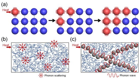
In general, the heat transfer in conventional crystalline materials is realized via a lattice vibration mechanism, as shown in Figure 1a [2]. External thermal energy is transformed to vibration energy in the crystalline materials and transferred to the surrounding atoms. Unlike the pure crystalline materials, the conduction of thermal energy in a polymer can be achieved via a phonon transfer process, as shown in Figure 1b [3].

Figure 1. (a) Mechanism of thermal conduction in a crystalline material. Schematic diagrams of heat transfer in (b) a pure polymer and (c) a polymer filled with a thermally conductive filler.
2. Polymer Composites with a Continuous 3D Architecture of Carbon Fillers
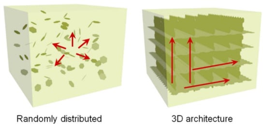
The preconstruction of a continuous 3D connected network with the conductive fillers is an efficient strategy for the preparation of the thermally conductive polymer composites by reducing the thermal resistance at the filler–matrix interface and between individual filler particles, as schematically displayed in Figure 2. The thermal conductivity values of the recently published polymer composites with a continuous 3D architecture of carbon fillers are summarized in Table 1.

Figure 2. Schematic illustrations of thermal conductance in polymer composites with randomly distributed carbon fillers and a continuous 3D architecture of carbon fillers.
| Fillers | Matrix | Filler Loading |
k (W·m−1·K−1) | Enhancement in k (%) | References |
|---|---|---|---|---|---|
| Graphen eaerogel |
1-octadecanol | 5.0 wt% | 4.28 | 94.5% | [4] |
| GO/GNP hybrid aerogel |
PEG | 0.45/1.8 wt% | 1.43 | 361% | [5] |
| CVD graphene network with CB | PDMS | 8 wt% | 0.686 | 222% | [6] |
| GO/GNP hybrid foam | Epoxy | 19.0 vol% | 35.5 | 884% | [7] |
| 3D CNT network | - | - | 5.40 | - | [8] |
| Expended graphite | Stearic acid | 40.0 wt% | 35.0 | - | [9] |
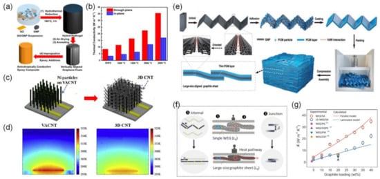
Graphene oxide (GO) is a graphene derivative with very good solubility and processability, produced by the chemical oxidation of graphite [10]. Feng et al. explained that the most important factors determining the thermal conductivity of 3D graphene network-based composites are the quality and density of the graphene 3D network [11]. In order to manufacture composite materials that satisfy both requirements, Yu et al. designed graphene hybrid foams with high density by the hydrothermal reduction of GO in the presence of GNPs (Figure 3a) [8]. Similar to the previously introduced hybrid graphene network, rGO acted as an interconnected network during the hydrothermal reduction process, while the incorporated GNPs played an important role in making the thermal conduction network denser. In addition to this process, graphitization of the graphene hybrid network at 2800 °C improved the quality of the graphene foams (removing the residual oxygen-containing functional groups and healing the defects of their reduced graphene oxide component). The resultant hybrid rGO/GNP/epoxy composites exhibited an ultrahigh through-plane thermal conductivity of 35.5 W·m−1·K−1 at a graphene loading of 19.0 vol% (Figure 3b).

Figure 3. (a) Schematic illustration of the preparation of 3D graphene hydrogel composites and (b) the thermal conductivity of the composites after treatment at different annealing temperatures [7]. Copyright the American Chemical Society. (c) Preparation procedure of the secondary CNTs and (d) thermal maps of the VACNT and 3D CNT [8]. Copyright Elsevier. (e) Schematic diagram for synthesizing phase change composites. (f) The configuration diagram of the compressed worm-like expanded graphite (WEG). The red circles represent the thermal resistance junctions between the adjacent WEG (or graphite sheets). The blue ellipses represent the partial WEG (or graphite sheets). The red arrows represent the heat flow. The yellow, semitransparent solid circles represent the connections between GNPs. (g) Thermal conductivity of the WEG/SA and 15-WEG/SA composite blocks as a function of the graphite loading [9]. Copyright Wiley.
Unlike the graphene aerogel structure, one dimensional shaped CNTs can form CNT arrays oriented in one direction, which has a great effect on the directional heat transfer of CNT array-based composite materials [12].
3. Polymer Composites with Thermally Conductive Yet Electrically Insulating Carbon Fillers
Although carbon fillers such as graphite, graphene, and CNT have ultra-high thermal conductivities [13][14][15], due to their high electrical conductivities, they have been limited in their use in various electronic parts, which should satisfy both thermal conductivity and electrical insulation at the same time [16]. Numerous techniques have been developed to suppress the electrical conductivities of the carbon materials while maintaining their intrinsic excellent thermal conductivities.
To prevent the formation of electrically conductive networks, carbon materials are usually coated with inorganic materials such as MgO [17], SiO2 [18], Al2O3 [19], and boron nitride (BN) [20]. Subsequently covering the carbon surface with amphiphilic materials and then with a ceramic layer is a suitable way to insulate the carbon material while avoiding the formation of defects through a harsh surface modification process. The thermally conductive but electrically insulating polymer composites were also obtained by the introduction of the hybrid materials of the electrically conductive carbon and insulating boron nitride. Band gap tuning is one of the smart approaches to develop electrically insulating carbon fillers for the preparation of thermally conductive polymer composites. Fluorination of carbon nanomaterials is an efficient method to tune their band gap via the structural transformation of the carbon–carbon bonds from sp2 to sp3 configuration [21].
4. Polymer Composites with Vertically Aligned Carbon Fillers
Table 2 summarizes the thermal conductivity values of the previously reported polymer composites with vertically aligned carbon fillers.
| Fillers | Matrix | Filler Loading |
k (W·m−1·K−1) | Enhancement in k (%) |
References |
|---|---|---|---|---|---|
| CF | Rubber | 13.2 wt% | 8.9 | 10,986% | [22] |
| GNF | PVDF | 25 vol% | 10.19 | - | [23] |
| GO | Epoxy | 15.79 wt% | 2.645 | 887% | [24] |
| Graphite | PA6/POE-g-MAH/PS | 10 wt% | 5.5 | - | [25] |
| Graphene | Epoxy | 44 vol% | 384.9 | 3570% | [26] |
| GO | Epoxy | 0.92 vol% | 2.13 | 1231% | [27] |
| GO | Epoxy | 1.5 wt% | 6.57 | 5890% | [28] |
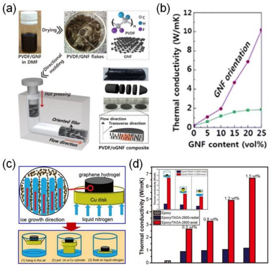
Park et al. fabricated polymer composites with high directional thermal conductivity by controlling the orientation of the graphene nanoflake (GNF) fillers [23]. They pointed out the need for the fabrication of polymer composites with a high through-plane thermal conductivity but low filler loading. Therefore, melt compression of poly(vinylidene fluoride) (PVDF) and GNF films was performed in an L-shape kinked tube to yield a polymer composite with preferentially aligned GNF fillers perpendicular to the melt flow direction (Figure 4a). The PVDF/GNF composite exhibited a through-plane thermal conductivity of 10.19 W·m−1·K−1 with 25 vol% GNF loading (Figure 4b).

Figure 4. (a) Schematic illustration of the fabrication process of GNFs preferentially aligned in PVDF through an L-shaped kinked tube. (b) Thermal conductivity of PVDF/GNF and PVDF/GNF composites with different GNF amounts [23]. Copyright the American Chemical Society. (c) Schematic illustration of the fabrication of vertically aligned graphene aerogels. (d) Thermal conductivity of the vertically aligned graphene aerogel composite [28]. Copyright Elsevier.
5. Stability of the Thermal Conductivity Performance of Polymer Composites
The stability of the thermal conductivity performance is an important factor that must be considered to design polymer composites for the heat dissipation applications. Xiao et al. achieved not only a high thermal conductivity, but also durability of the carbon-based polymer composites by fabricating a carbon fiber foam with a mixture of cellulose and carbon fiber, using the ice template method and then compounding it with PDMS [29]. When loaded with 12.8 vol% of the filler, the polymer composite showed a thermal conductivity of 6.04 W·m−1·K−1, and as a result of repeated heating and cooling cycle tests between 25 °C and 125 °C, it exhibited stable heat dissipation performance without significant degradation.
6. Future Outlooks
Despite the intensive efforts of many researchers, there are still many problems to be solved in order for the research of polymer composites to move from academic research to industrial applications. First, a mass production method for the formation of the 3D architecture and vertical alignment of carbon fillers has never been developed. It requires a novel approach that should be cost-effective and simpler than the previously published methods. Second, we need to find a way to minimize the thermal interface resistance between the carbon fillers and polymer matrix. Finally, it is necessary to develop an optimal method for preparing a thermally conductive yet electrically insulating carbon filler. In addition, research on the structural control and alignment of the electrically insulating carbon filler should be continued for the application of the carbon-based polymer composites to the thermal management of cutting-edge electronic devices in the future.
This entry is adapted from the peer-reviewed paper 10.3390/polym13081312
References
- Yan, Z.; Liu, G.; Khan, J.M.; Balandin, A.A. Graphene quilts for thermal management of high-power GaN transistors. Nat. Commun. 2012, 3, 1–8.
- Burger, N.; Laachachi, A.; Ferriol, M.; Lutz, M.; Toniazzo, V.; Ruch, D. Review of thermal conductivity in composites: Mechanisms, parameters and theory. Prog. Polym. Sci. 2016, 61, 1–28.
- Ma, D.; Arora, A.; Deng, S.; Xie, G.; Shiomi, J.; Yang, N. Quantifying phonon particle and wave transport in silicon nanophononic metamaterial with cross junction. Mater. Today Phys. 2019, 8, 56–61.
- Yang, J.; Li, X.; Han, S.; Yang, R.; Min, P.; Yu, Z.-Z. High-quality graphene aerogels for thermally conductive phase change composites with excellent shape stability. J. Mater. Chem. A 2018, 6, 5880–5886.
- Yang, J.; Qi, G.-Q.; Liu, Y.; Bao, R.-Y.; Liu, Z.-Y.; Yang, W.; Xie, B.-H.; Yang, M.-B. Hybrid graphene aerogels/phase change material composites: Thermal conductivity, shape-stabilization and light-to-thermal energy storage. Carbon 2016, 100, 693–702.
- Zhao, Y.-H.; Zhang, Y.-F.; Wu, Z.-K.; Bai, S.-L. Synergic enhancement of thermal properties of polymer composites by graphene foam and carbon black. Compos. Part B Eng. 2016, 84, 52–58.
- An, F.; Li, X.; Min, P.; Liu, P.; Jiang, Z.-G.; Yu, Z.-Z. Vertically Aligned High-Quality Graphene Foams for Anisotropically Conductive Polymer Composites with Ultrahigh Through-Plane Thermal Conductivities. ACS Appl. Mater. Interfaces 2018, 10, 17383–17392.
- Kong, Q.; Bodelot, L.; Lebental, B.; Lim, Y.D.; Shiau, L.L.; Gusarov, B.; Tan, C.W.; Liang, K.; Lu, C.; Tan, C.S.; et al. Novel three-dimensional carbon nanotube networks as high performance thermal interface materials. Carbon 2018, 132, 359–369.
- Wu, S.; Li, T.; Tong, Z.; Chao, J.; Zhai, T.; Xu, J.; Yan, T.; Wu, M.; Xu, Z.; Bao, H.; et al. High-Performance Thermally Conductive Phase Change Composites by Large-Size Oriented Graphite Sheets for Scalable Thermal Energy Harvesting. Adv. Mater. 2019, 31, 1905099.
- Chandu, B.; Kurmarayuni, C.M.; Kurapati, S.; Bollikolla, H.B. Green and economical synthesis of graphene–silver nanocomposite exhibiting excellent photocatalytic efficiency. Carbon Lett. 2020, 30, 225–233.
- Zhang, F.; Feng, Y.; Feng, W. Three-dimensional interconnected networks for thermally conductive polymer composites: Design, preparation, properties, and mechanisms. Mater. Sci. Eng. R Rep. 2020, 142, 100580.
- Ivanov, I.; Puretzky, A.; Eres, G.; Wang, H.; Pan, Z.; Cui, H.; Jin, R.; Howe, J.; Geohegan, D.B. Fast and highly anisotropic thermal transport through vertically aligned carbon nanotube arrays. Appl. Phys. Lett. 2006, 89, 223110.
- Li, C.; Tan, L.-Y.; Zeng, X.-L.; Zhu, D.-L.; Sun, R.; Xu, J.-B.; Wong, C.-P. Polymer composites with high thermal conductivity optimized by polyline-folded graphite paper. Compos. Sci. Technol. 2020, 188, 107970.
- Dai, W.; Ma, T.; Yan, Q.; Gao, J.; Tan, X.; Lv, L.; Hou, H.; Wei, Q.; Yu, J.; Wu, J.; et al. Metal-Level Thermally Conductive yet Soft Graphene Thermal Interface Materials. ACS Nano 2019, 13, 11561–11571.
- Keshtkar, M.; Mehdipour, N.; Eslami, H. Thermal Conductivity of Polyamide-6,6/Carbon Nanotube Composites: Effects of Tube Diameter and Polymer Linkage between Tubes. Polymers 2019, 11, 1465.
- Hu, T.; Song, Y.; Di, J.; Xie, D.; Teng, C. Highly thermally conductive layered polymer composite from solvent-exfoliated pristine graphene. Carbon 2018, 140, 596–602.
- Zhang, J.; Du, Z.; Zou, W.; Li, H.; Zhang, C. MgO nanoparticles-decorated carbon fibers hybrid for improving thermal conductive and electrical insulating properties of Nylon 6 composite. Compos. Sci. Technol. 2017, 148, 1–8.
- Kim, Y.; Kim, M.; Seong, H.-G.; Jung, J.Y.; Baeck, S.-H.; Shim, S.E. Roles of silica-coated layer on graphite for thermal conductivity, heat dissipation, thermal stability, and electrical resistivity of polymer composites. Polymer 2018, 148, 295–302.
- Sun, R.; Yao, H.; Zhang, H.-B.; Li, Y.; Mai, Y.-W.; Yu, Z.-Z. Decoration of defect-free graphene nanoplatelets with alumina for thermally conductive and electrically insulating epoxy composites. Compos. Sci. Technol. 2016, 137, 16–23.
- Su, Z.; Wang, H.; Tian, K.; Huang, W.; Xiao, C.; Guo, Y.; He, J.; Tian, X. The combination of π-π interaction and covalent bonding can synergistically strengthen the flexible electrical insulating nanocomposites with well adhesive properties and thermal conductivity. Compos. Sci. Technol. 2018, 155, 1–10.
- Feng, W.; Long, P.; Feng, Y.; Li, Y. Two-Dimensional Fluorinated Graphene: Synthesis, Structures, Properties and Applications. Adv. Sci. 2016, 3, 1500413.
- Uetani, K.; Ata, S.; Tomonoh, S.; Yamada, T.; Yumura, M.; Hata, K. Elastomeric Thermal Interface Materials with High Through-Plane Thermal Conductivity from Carbon Fiber Fillers Vertically Aligned by Electrostatic Flocking. Adv. Mater. 2014, 26, 5857–5862.
- Jung, H.; Yu, S.; Bae, N.-S.; Cho, S.M.; Kim, R.H.; Cho, S.H.; Hwang, I.; Jeong, B.; Ryu, J.S.; Hwang, J.; et al. High Through-Plane Thermal Conduction of Graphene Nanoflake Filled Polymer Composites Melt-Processed in an L-Shape Kinked Tube. ACS Appl. Mater. Interfaces 2015, 7, 15256–15262.
- Han, D.; Zhao, Y.-H.; Zhang, Y.-F.; Bai, S.-L. Vertically and compactly rolled-up reduced graphene oxide film/epoxy composites: A two-stage reduction method for graphene-based thermal interfacial materials. RSC Adv. 2015, 5, 94426–94435.
- Jia, Y.; He, H.; Geng, Y.; Huang, B.; Peng, X. High through-plane thermal conductivity of polymer based product with vertical alignment of graphite flakes achieved via 3D printing. Compos. Sci. Technol. 2017, 145, 55–61.
- Zhang, Y.-F.; Ren, Y.-J.; Bai, S.-L. Vertically aligned graphene film/epoxy composites as heat dissipating materials. Int. J. Heat Mass Transf. 2018, 118, 510–517.
- Lian, G.; Tuan, C.-C.; Li, L.; Jiao, S.; Wang, Q.; Moon, K.-S.; Cui, D.; Wong, C.-P. Vertically Aligned and Interconnected Graphene Networks for High Thermal Conductivity of Epoxy Composites with Ultralow Loading. Chem. Mater. 2016, 28, 6096–6104.
- Li, X.-H.; Liu, P.; Li, X.; An, F.; Min, P.; Liao, K.-N.; Yu, Z.-Z. Vertically aligned, ultralight and highly compressive all-graphitized graphene aerogels for highly thermally conductive polymer composites. Carbon 2018, 140, 624–633.
- Hou, X.; Chen, Y.; Dai, W.; Wang, Z.; Li, H.; Lin, C.-T.; Nishimura, K.; Jiang, N.; Yu, J. Highly thermal conductive polymer composites via constructing microphragmites communis structured carbon fibers. Chem. Eng. J. 2019, 375, 121921.
