It has been a feasible approach to build an antenna, in view of the potential advantages they offer. One of the recent trends in dielectric resonator antenna research is the use of compound and hybrid structures. Several considerable investigations have been already underway showing quite interesting and significant features in bandwidth, gain, and generation of circular polarization.
- CP radiation
- microstrip antenna
- dielectric-resonator antenna
- hybrid dielectric resonator antenna
- wide-band antennas
- multi-functional antennas
1. Introduction
The radiation mechanism of various types of antennas and their radiation fundamentals, focusing on the concepts of circular polarization, are comprehensively discussed in [1,2]. Circularly polarized (CP) antennas can offer a consistent or reliable system connection between the transmitter and receiver, since the polarization of the antennas is always associated. In and around the intended resonant frequency, two modes orthogonal to each other with a phase-shift of 90° are desired for circular polarization. Therefore, using receiver antennas with the same phase center and orthogonal polarizations can avoid location-induced phase variation.
2. Classification and Progress of Dielectric Antennas
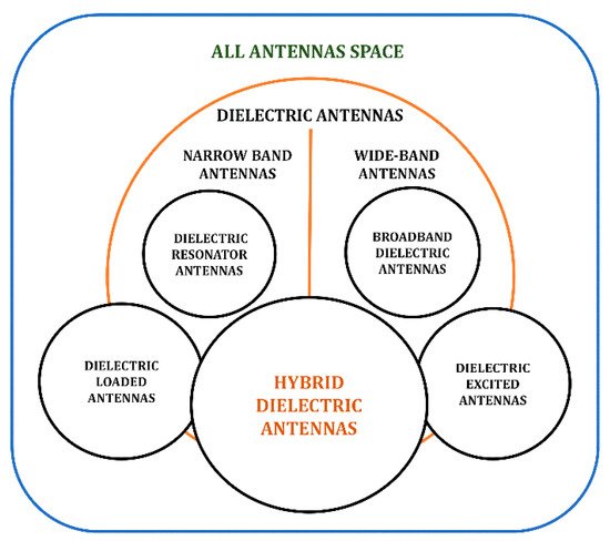
The past review studies of the dielectric resonator antennas have been summarized in Table 1 to highlight the various significant radiation and design aspects. The stored energy inside the dielectric is exceptionally high and it is difficult for external objects to detune the device [51,52,53]. DR can radiate from all surfaces, rendering high radiation efficiency and low Q-factor.
| Year | Past Review Highlights | Reference |
|---|---|---|
| 1994 |
|
[22] |
| 2005 |
|
[23] |
| 2006 |
|
[41] |
| 2010 |
|
[24] |
| 2010 |
|
[25] |
| 2012 |
|
[26] |
| 2014 |
|
[27] |
| 2015 |
|
[28] |
| 2016 |
|
[29] |
| 2017 |
|
[30] |
| 2017 |
|
[31] |
| 2019 |
|
[32] |
| 2020 |
|
[33] |
The primary radiating component of the Dielectric Loaded Antennas is a conducting element and the dielectric modifies the medium, imparting significant performance advantages [57,58,59,60,61]. Dielectric antennas can be used to excite parasitic copper antennas or vice versa. In this class of antennas, often the conductor forms the major radiating part of the antenna. There are bandwidth advantages in this dielectric–copper hybrid approach of the Dielectric Excited Antennas [62,63,64,65].
4. Circularly Polarized DR Based Hybrid Antennas
4.1. Wideband Hybrid Antennas with CP Radiation
Several CP radiation techniques and respective design methods have been implemented independently for microstrip and dielectric resonator antennas. However, CP radiation techniques for hybrid dielectric resonator antennas over a wide-bandwidth are challenging [106]. A compact dielectric-loaded aperture-coupled microstrip antenna is reported for L-band mobile satellite applications with CP radiation. Two dielectric-inserts [107] along the edges of the square patch are positioned for the required reduced frequency shift of 30% to the lower-side, and the cross-slot aperture creates the two-orthogonal modes desired for CP radiation with 2.5% of 3 dB AR bandwidth compared to traditional CP square patch. Similarly, four dielectric inserts [108] are used under the square patch positioned at the edges with a cross-slot feed to obtain the CP radiation. A considerable reduction of antenna size is possible by inserting dielectric blocks beneath the patch, while the desired bandwidth and the axial ratio are also achieved for L-band applications [109].
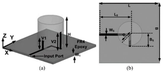
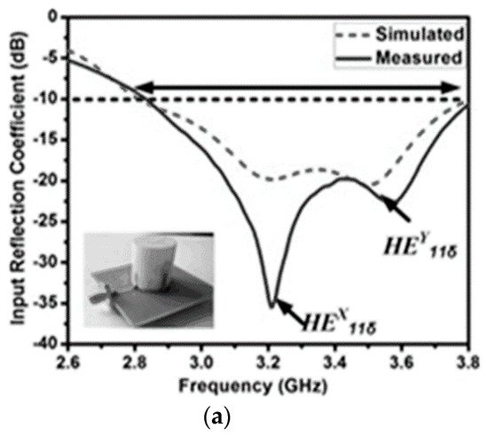
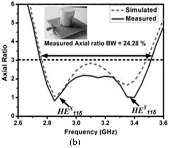
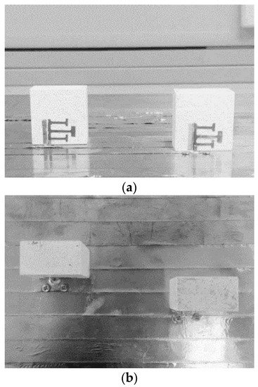
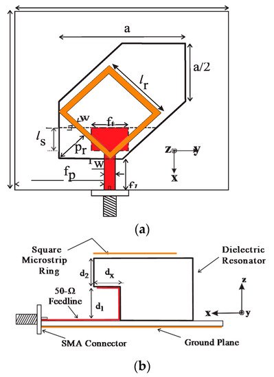
A modified cross-slot is concurrently acting as a radiator as well as the feeding element to the DR antenna. The resonances of modified cross-slot and DR elements are combined to form a wideband CP radiated hybrid DRA [114] with a 3 dB AR bandwidth of 24.6% (2.25–2.88 GHz) and 10 dB return-loss bandwidth of 28.6% (2.19–2.92 GHz). A hybrid structure is formed, combining a stair-shaped DR element with an open-ended slot [115] on the ground plane, which is reported for wideband CP radiation. The open-ended slot on the ground plane is responsible for a lower frequency of resonance (at 4.5 GHz) and, in turn, a wide axial-ratio bandwidth is obtained. By varying different parameters of the hybrid structure, a wide impedance bandwidth of 71.7% (3.844–8.146 GHz) and an AR band-width of 46% (4.15–6.63 GHz) is obtained. A simple feed network along with two vertical strip-lines are arranged [116] as shown in Figure 3 to produce orthogonal fields of hybrid HEx11$ and HEy11$ modes (presented in Figure 4) in the cylindrical DR element for wide CP radiation with AR bandwidth of 24.6% (2750–3520 MHz). The length of the vertical strip-lines along the cylindrical surface of the DRA controls the LHCP and RHCP radiation. A circularly polarized multiple inputs multiple output (MIMO) hybrid antenna [117] is formed by a parasitic patch, and the conformal strips along the sidewalls of two identical rectangular DR elements are shown in Figure 5.
4.2. Multi-Functional Hybrid Antennas with CP Radiation
A combination of ring-shaped microstrip and cylindrical DR elements has been designed for dual functional applications. In this particular configuration, an independently operated microstrip-based annular ring and cylindrical dielectric resonators are used to form a hybrid structure [119], to produce dual CP-radiated bands at 4.2 GHz and 6.4 GHz, respectively, with the return-loss bandwidth higher than 6% at each band. By short-circuiting the annular ring to the ground, the perturbation of radiation patterns can be avoided after assembling both the resonators significantly. However, the shift in the resonant frequency due to the short circuit can be adjusted by modifying the annular ring dimensions. A dual CP hybrid DR antenna is formed [120] by introducing a zonal slot cut on a conducting-cavity, along with a DR element. The lower and upper bands are achieved by zonal slot and DR elements positioned on the side-wall and top of the cavity wall. An L-shaped probe is used to feed the zonal slot antenna in the cavity and an indirect cross-coupling slot is incorporated to feed the DR element. Two even cuts are introduced to achieve CP radiation fields, and another cut is introduced in the zonal slot to obtain the desired AR. Regular unequal lengths of cross-slots under the DR element introduces another perpendicular degenerated mode for CP fields. A cross-slot is used as an aperture feed and as a radiator to produce dual-CP-bands [121].
4.3. Dual-Sense Polarized Hybrid Antennas
6. Future Scope and Challenges
-
Employing metamaterial concepts and magnetic LC resonators on the metallic patch, considering dielectric-loaded patch and metallic patch loaded on top of dielectric antennas.
-
Various available fractal concepts can be employed on the patch as well as the DR elements particularly to achieve multifunctional bands of resonance.
-
Existing bandwidth and gain enhancement techniques can be applied for the combined form of hybrid DR-based antennas.
-
A combination of a metallic waveguide, microstrip, and DR antennas with a proper feeding mechanism can be developed for future radar applications.
This entry is adapted from the peer-reviewed paper 10.3390/s21124100