Multiferroic magnetoelectric (ME) materials with the capability of coupling magnetization and electric polarization have been providing diverse routes towards functional devices and thus attracting ever-increasing attention. The typical device applications include sensors, energy harvesters, magnetoelectric random access memories, tunable microwave devices and ME antennas etc. Among those application scenarios, ME sensors are specifically focused in this review article. We begin with an introduction of materials development and then recent advances in ME sensors are overviewed. Engineering applications of ME sensors are followed and typical scenarios are presented. Finally, several remaining challenges and future directions from the perspective of sensor designs and real applications are included.
- multiferroic
- magnetoelectric
- sensors
- object detection
- magnetic localization
- current sensing
- biological magnetic measurement
- non-destructive testing
- displacement sensing
1. Introduction
Multiferroic materials have been recently attracting ever-increasing attention because of the capability of coupling at least two ferric orders, i.e., ferroelectricity, ferromagnetism, or ferroelasticity, and the vast potential for multifunctional devices applications [1][2][3][4][5]. A control of polarization P by external magnetic field H (direct ME (DME) effect) or a manipulation of magnetization M by an electric field E (converse ME (CME) effect) can be realized in multiferroic magnetoelectric (ME) materials [6]. Compared with single-phase ME material, ME heterostructures and ME laminates perform greatly enhanced coupling capability, which is generally characterized by ME coefficient αME [7][8][9]. After a development of nearly half a century, tremendous progress regarding ME composites and related device applications has been reported [1][2][3][6][10][11][12][13][14][15][16][17][18][19].
2. Materials for ME Sensors
2.1. Bulk ME Laminates
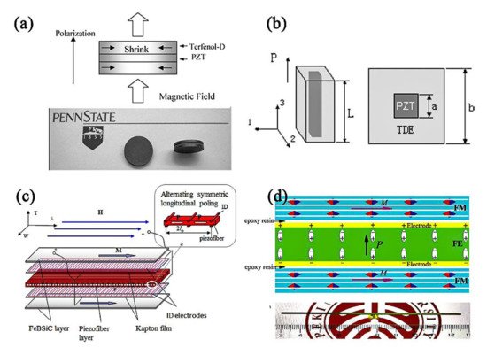
In 2017, Chu et al. reported a 1-1 type ME composites, which consisted of a [011]-oriented Pb(Mg,Nb)O3-PbZrO3-PbTiO3 (PMN-PZT) single crystal fiber and laser-treated amorphous alloy Metglas. The 1-1 type ME composite featured the one-dimensional configuration as shown in Figure 1d [8]. The laser treatment could decrease magnetic hysteresis loss of Metglas and thereby enhance the Q value of the ME resonator. In addition, the fiber configuration effectively utilized the magnetic flux concentration effect occurring in Metglas layers. More importantly, this 1-D configuration favored the longitudinal vibration mode of ME laminates. A ME coupling coefficient of ~7000 V/cm⋅Oe, that was nearly seven times higher than the best result published previously, was finally realized, opening a door to develop new ME devices, e.g., resonant magnetic receivers in particular [8]. In addition, a high ME coefficient of 29.3 V/cm·Oe at non-resonant frequency was also achieved for our 1-1 type composites. Note, only one single crystal was consumed in this case, while previous 2-1 type composites normally took five crystals. In 2020, the resonant ME coefficient of 1-1 type ME composites was further enhanced to 12,500 V/cm·Oe by using a hard piezo-crystal Mn-PMN-PZT [9]. A summary of the field coupling coefficient of different ME laminates, i.e., 0-3, 2-2, 2-2.1-1 ME laminates, is given in Table 1.
Table 1. Some ME laminates and their ME coupling performances.
|
Composition |
Year |
Connectivity |
Working Mode |
|
|
|---|---|---|---|---|---|
|
Terfenol-D/PZT [36] |
2007 |
3-1 |
L-L |
0.5 |
18.2 |
|
NiFe2O4/PZT [38] |
2001 |
2-2 |
L-T |
1.5 |
/ |
|
Terfenol-D/PZT [27] |
2002 |
2-2 |
L-T |
5 |
/ |
|
Metglas/PVDF [39] |
2006 |
2-2 |
L-T |
7.2 |
310 |
|
Metglas/P(VDF-TrFE) [40] |
2011 |
2-2 |
L-L |
17.7 |
383 |
|
Lanthanum gallium tantalite/ permendur [41] |
2012 |
2-2 |
/ |
2.3 |
720 |
|
FeCoSiB/(Pt)/AlN in vacuum [42] |
2013 |
2-2 |
L-T |
/ |
20,000 |
|
FeCoSiB/(Pt)/AlN [43] |
2016 |
2-2 |
L-T |
/ |
5000 |
|
Metglas/LiNbO3 [44] |
2018 |
2-2 |
L-T |
1.9 |
1704 |
|
FeBSiC/PZT [30] |
2006 |
2-1 |
L-L |
22 |
500 |
|
Metglas/PMN-PT [31] |
2011 |
2-1 |
L-L |
45 |
1100 |
|
Metglas/PMN-PT without laser treatment [8] |
2017 |
1-1 |
L-T |
29.3 |
5500 |
|
Metglas/PMN-PT with laser treatment [8] |
2017 |
1-1 |
L-T |
22.9 |
7000 |
|
Metglas/Mn-PMN-PZT with laser treatment [9] |
2020 |
1-1 |
L-T |
23.6 |
12,500 |
Note: Connectivity. We use different number to represent the connectivity of each individual phase. For example, 1-3 type composite means one-phase fiber (denoted by 1) was embedded in the matrix of another phase (denoted by 3); 2-2 type composite means laminated structure (each phase has a plane configuration denoted by 2); 2-1 type composite means one-phase fiber was laminated with another phase plate; 1-1 type means both phases are in the form of fiber configuration. Working mode. L-L, L-T means longitudinal vibrations with longitudinal magnetization and transverse polarization(L-L) or transverse magnetization and transverse polarization (L-T).
2.2. MEMS and NEMS ME Laminates
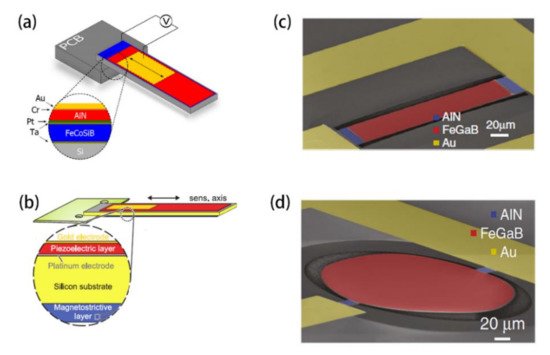
3. Advances in ME Sensors
To assess the performance of a general magnetic sensor, several critical parameters should be considered, i.e., limit of detection (LoD), sensitivity, working temperature, dynamic range, power consumption, size and the cost, but one should note LoD and sensitivity should be given a high priority when taking the research stage of ME sensors into consideration. With respect to the LoD of ME sensors, the ME coupling coefficient and the voltage noise level should be considered equally. Table 1 summarizes the ME coefficients of typical ME composites. The total noise level Nt comes from both internal and external noise sources. The internal noise is dominated by the dielectric loss NDE and the leakage resistance NR, which can be written as follows [32][33]:

where k is the Boltzmann constant (1.38 × 10⁻²³ J K−1), T is the temperature in Kelvin, Cp is the static capacitance, tan δ is the dielectric loss, f is the frequency in Hz and R is the DC resistance of the ME sensor. The total noise density Nt has a 1/f spectrum and makes the magnetic field detection at low frequency much more difficult. On the other hand, ME sensors are susceptible to external environment variations, e.g., temperature fluctuation and base vibration, which typically occurs in low frequency as well [7][54]. We will discuss the current advances in ME sensors focusing on the improvement of LoD in the following sections.
3.1. Low-Frequency Magnetic Sensor
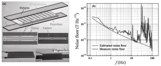
In 2011, Wang et al. reported the realization of an extremely low limit of detection through a combination of giant ME coupling in 2-1 type ME composites and a reduction in each noise source. Giant ME coupling was achieved by optimizing the stress transfer in multi-push-pull mode, the thickness ratio of Metglas to piezofiber, and the ID electrodes distribution on Kapton (Figure 3a). Experimental results showed that an extremely low equivalent magnetic noise of 5.1 pT/√Hz at 1 Hz was obtained (Figure 3b) [33].
The problem in 2-1 type ME composites based on multi-push-pull working mode is the difficulty to fully polarize the piezoelectric phase and the capacitance in this configuration is usually small. In 2012, Li et al. further pointed out that the equivalent magnetic noise could be reduced by a factor of √N through stacking some number N of ME sensor units in parallel [32]. From the perspective of reducing the total noise level Nt, connecting N ME sensor units in series could be also effective to increase the detection capability. For example, Fang et al. reported a 2-1 ME sensor based on multi-L-T mode, of which the schematic is shown in Figure 4a,b [55]. In this case, the ME charge coefficient could be kept at a high level while the static capacitance and the leakage current could be decreased remarkably by increasing the number (N) of piezoelectric crystal. As a result, the measured equivalent magnetic noise (EMN) of the Metglas/Mn-PMNT composite was as low as 0.87 pT/√Hz at 30 Hz for N = 7, which was 1.8 times lower than that for N = 1 (see Figure 4c,d) [55].
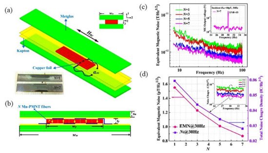
Figure 4. 3D structure of Metglas/Mn-PMNT ME composite (a) and its cross-sectional diagram (b); (c) The EMN over the frequency range of 8 Hz < f < 100 Hz. (d)The EMN and Nt of different Metglas/Mn-PMNT sensors at 30 Hz [55].
In 2011, frequency conversion technology (FCT) was proposed to circumvent the large 1/f noise for active ME sensors [56][57][58][59][60]. Quasi-static or extremely-low frequency magnetic fields can be effectively detected in this case. For example, Chu et al. realized a limit of detection of 33 pT/√Hz at 0.1 Hz by using amplitude modulation method combined with FCT in 1-1 type magnetoelectric composites [61]. During the measurement, a carrier signal and a modulation signal were both applied to the ME sensor.
Figure 5a,b demonstrates the fundamental modulation phenomenon and the block diagram of the correlation detection scheme with respect to an amplitude modulation signal SMod (t). The output voltage waveform was observed by a mixed signal oscilloscope. The ME sensor was driven by 100 Hz carrier signal and the modulation frequency is 10 Hz. Once the low-frequency modulation field HAC with an intensity of 10−6 T was applied, a clear amplitude modulation (envelope) signal was generated due to the intrinsic frequency mixing characteristic in ME sensors, as shown in Figure 5a(ii).
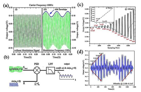
In order to test the limit of detection by using this amplitude modulation method, the time constant decreased to 10 ms and the demodulated signal from time domain waveform via a lock-in amplifier was analyzed. Figure 5c shows the measured output voltage in response to an applied 100 mHz HAC varying from 0.1 to 10 nT. Clearly, a standard linear-response to HAC within this range was obtained as given in the inset in Figure 5c. Accordingly, the limit of resolution (LOR) of the ME sensor based on this amplitude modulation method was determined to be as low as 100 pT. To confirm this LOR, Figure 5d further verified it by measurement. Considering an equivalent noise bandwidth (ENBW)of 7.8 Hz corresponding to the given measurement system, the calculated LoD was then calculated as 33 pT/√Hz at 0.1 Hz.
3.2. Resonant-Frequency Magnetic Sensor
ME laminates can be viewed as resonators from the perspective of mechanics and resonant phenomenon is also able to enhance the ME coupling coefficient and thus to improve the detection ability [10]. In this regard, ME sensors could be highly competitive over other magnetic field sensors, e.g., fluxgate sensor and optical pump magnetometer. Using a 2-2 ME composite, Dong et al. reported an enhanced LoR of 1.2 pT early in 2005 (see Figure 6a) [29]. As for MEMS ME magnetic sensor, Yarar et al. developed a low temperature deposition route of very high quality AlN film, allowing the reversal process flow. Correspondingly, the LoD was enhanced by almost an order of magnitude approaching 400 fT/Hz1/2 at the electromechanical resonance, as shown in Figure 6b [43]. Based on the giant resonance ME coupling coefficient in 1-1 type ME laminate, a superhigh resonant magnetic-field sensitivity close to be 135 fT (see Figure 6c) was further obtained by Chu et al. [8], which indicates great potential for 1-1 type ME composites in the field of eddy current sensing, space magnetic sensing and active magnetic localizing [8][61]. In 2018 Turutin et al. reported a new ME composite consisting of the y + 140° cut congruent lithium niobate piezoelectric plates with an antiparallel polarized “head-to-head” bidomain structure and magnetostrictive material Metglas [44]. Based on this 2-2 ME bimorph, the equivalent magnetic noise spectral density was only 92 fT/Hz1/2 and the directly measured resolution was found to be 200 fT at a bending resonance frequency of 6862 Hz (see Figure 6d), but one should note that the bandwidth of resonant ME sensors is normally below 1 kHz due to the high mechanical quality factor, which is a major limitation facing practical engineering applications [8][44][62]. It should however be noted that resonant ME sensors are greatly limited by the narrow bandwidth and specifically suited applications need to be considered.
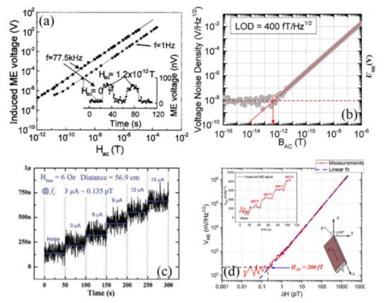
Figure 6. (a) Magnetic field detection limit measurements at frequencies of f = 1 Hz and f = 77.5 kHz (resonance condition), respectively [29]; (b)The measurement of LOD for MEMS ME sensor [43], (c) for 1-1 typed ME sensor [8] and (d) for a 2-2 ME bimorph [44].
3.3. DC Magnetic Sensor
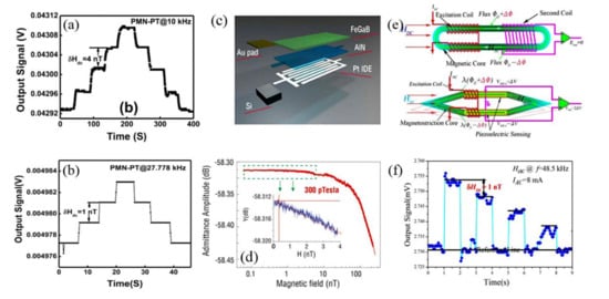
|
Composition |
Working Mode |
Sensing Mode |
|
|
|
Low-frequency magnetic field sensing |
Metglas/Mn-PMNT [67] |
Longitudinal vibration (Multi-L-T) |
Passive sensing |
|
|
Metglas/PMN-PT [33] |
Longitudinal vibration (Multi-push-pull) |
Passive sensing |
|
|
|
Metglas/PMN-PZT [55] |
Longitudinal vibration (L-T) |
Active Modulation |
|
|
|
Resonant magnetic field sensing |
Metglas/ LiNbO3 [44] |
bending mode |
Direct Sensing |
92 fT/√Hz |
|
FeCoSiB/(Pt)/AlN [43] |
bending mode |
Direct Sensing |
400 fT/√Hz |
|
|
Metglas/PMN-PZT [8] |
Longitudinal vibration (L-T) |
Direct Sensing |
123 fT/√Hz |
|
|
DC magnetic field sensing |
langatate-Metglas [64] |
bending mode |
Nonlinear ME effect |
10 nT |
|
Metglas/PMN-PZT [9] |
Longitudinal vibration (L-T) |
Linear ME effect |
1 nT |
|
|
FeCoSiB/(Pt)/AlN [26] |
Lateral vibration |
Delta-E effect |
0.8 nT |
|
|
FeCoSiB/(Pt)/AlN [51] |
Lateral vibration |
Delta-E effect |
0.4 nT |
Table 3. Performance Comparison with commercially available magnetometer for 1 Hz magnetic field sensing.
|
Magnetometer |
Working Temperature |
Power Consumption (mW) |
Typical Size |
|
Limitations |
|
ME sensor [33] |
0 °C to +50 °C ① |
<1 |
80 mm × 10 mm @ ME composites |
5.1 |
Vibration interference |
|
Magnetoresistive sensor ② |
−40 °C to +125 °C |
~0.02 |
6 mm × 5 mm × 1.5 mm @ sensing element |
100 |
Low sensitivity |
|
Giant magneto-impedance sensor ③ |
−20 °C to +60 °C |
75 |
35 mm × 11 mm × 4.6 mm @ sensing element |
15–25 |
Low sensitivity |
|
Fluxgate magnetometer ④ |
−40 °C to +70 °C |
350 |
ø100 mm × 125 mm @ system size |
2–6 |
Power consumption |
|
Optically pumped magnetometer ⑤ |
−35 °C to +50 °C |
>12,000 |
175 cm × 28 cm × 28 cm @ system size |
4 |
Complex setup |
|
SQUID magnetometer [68] |
<−196 °C |
>1000 |
12.5 mm × 12.5 mm @ chip size |
<0.005 |
Cooling |
① Estimated from the data in ref. [64]; ② Based on commercial product TMR9001 in MultiDimension Technology Co., Ltd. (Zhangjiagang Free Trade Zone, Jiangsu Province, China); ③ Based on commercial product MI-CB-1DH in AICHI STEEL CORPORATION (Tōkai city, Aichi Prefecture, Japan); ④ Based on commercial product Mag03 from Bartington Instruments Ltd (Witney, Oxon, OX28 4GG United Kingdom).; ⑤ Based on commercial product G882 marine magnetometer from GEOMETRICS, INC (San Jose, CA, USA).
4. Engineering Applications of ME Sensors
This entry is adapted from the peer-reviewed paper 10.3390/act10060109
References
- Ma, J.; Hu, J.; Li, Z.; Nan, C.W. Recent progress in multiferroic magnetoelectric composites: From bulk to thin films. Adv. Mater. 2011, 23, 1062–1087.
- Hu, J.-M.; Nan, T.; Sun, N.X.; Chen, L.-Q. Multiferroic magnetoelectric nanostructures for novel device applications. MRS Bull. 2015, 40, 728–735.
- Hu, J.-M.; Duan, C.-G.; Nan, C.-W.; Chen, L.-Q. Understanding and designing magnetoelectric heterostructures guided by computation: Progresses, remaining questions, and perspectives. NPJ Comput. Mater. 2017, 3, 1–21.
- Kleemann, W. Multiferroic and magnetoelectric nanocomposites for data processing. J. Phys. D Appl. Phys. 2017, 50, 223001.
- Lawes, G.; Srinivasan, G. Introduction to magnetoelectric coupling and multiferroic films. J. Phys. D Appl. Phys. 2011, 44, 243001.
- Palneedi, H.; Annapureddy, V.; Priya, S.; Ryu, J. Status and Perspectives of Multiferroic Magnetoelectric Composite Materials and Applications. Actuators 2016, 5, 9.
- Chu, Z.; PourhosseiniAsl, M.; Dong, S. Review of multi-layered magnetoelectric composite materials and devices applications. J. Phys. D Appl. Phys. 2018, 51, 243001.
- Chu, Z.; Shi, H.; Shi, W.; Liu, G.; Wu, J.; Yalng, J.; Dong, S. Enhanced Resonance Magnetoelectric Coupling in (1-1) Connectivity Composites. Adv. Mater. 2017, 29, 1606022.
- PourhosseiniAsl, M.; Gao, X.; Kamalisiahroudi, S.; Yu, Z.; Chu, Z.; Yang, J.; Lee, H.-Y.; Dong, S. Versatile power and energy conversion of magnetoelectric composite materials with high efficiency via electromechanical resonance. Nano Energy 2020, 70, 104506.
- Nan, C.-W.; Bichurin, M.I.; Dong, S.; Viehland, D.; Srinivasan, G. Multiferroic magnetoelectric composites: Historical perspective, status, and future directions. J. Appl. Phys. 2008, 103, 031101.
- Fiebig, M. Revival of the magnetoelectric effect. J. Phys. D Appl. Phys. 2005, 38, R123–R152.
- Zhai, J.; Xing, Z.; Dong, S.; Li, J.; Viehland, D. Magnetoelectric Laminate Composites: An Overview. J. Am. Ceram. Soc. 2008, 91, 351–358.
- Wang, Y.; Li, J.; Viehland, D. Magnetoelectrics for magnetic sensor applications: Status, challenges and perspectives. Mater. Today 2014, 17, 269–275.
- Gutierrez, J.; Lasheras, A.; Martins, P.; Pereira, N.; Barandiaran, J.M.; Lanceros-Mendez, S. Metallic Glass/PVDF Magnetoelectric Laminates for Resonant Sensors and Actuators: A Review. Sensors 2017, 17, 1251.
- Sreenivasulu, G.; Qu, P.; Petrov, V.; Qu, H.; Srinivasan, G. Sensitivity Enhancement in Magnetic Sensors Based on Ferroelectric-Bimorphs and Multiferroic Composites. Sensors 2016, 16, 262.
- Annapureddy, V.; Palneedi, H.; Hwang, G.-T.; Peddigari, M.; Jeong, D.-Y.; Yoon, W.-H.; Kim, K.-H. Magnetic energy harvesting with magnetoelectrics: An emerging technology for self-powered autonomous systems. Sustain. Energy Fuels 2017, 1, 2039–2052.
- Vopson, M.M. Fundamentals of Multiferroic Materials and Their Possible Applications. Crit. Rev. Solid State Mater. Sci. 2015, 40, 223–250.
- Gao, X.; Yan, Y.; Carazo, A.V.; Dong, S.; Priya, S. Low-temperature cofired unipoled multilayer piezoelectric transformers. IEEE Trans. Ultrason. Ferroelectr. Freq. Control 2017, 65, 513–519.
- Yang, N.; Wu, H.; Wang, S.; Yuan, G.; Zhang, J.; Sokolov, O.; Bichurin, M.I.; Wang, K.; Wang, Y. Ultrasensitive flexible magnetoelectric sensor. APL Mater. 2021, 9, 021123.
- Dong, S.; Liu, J.-M.; Cheong, S.-W.; Ren, Z. Multiferroic materials and magnetoelectric physics: Symmetry, entanglement, excitation, and topology. Adv. Phys. 2015, 64, 519–626.
- Astrov, D.N. Magnetoelectric Effect In Chromium Oxide. Sov. Phys. Jetp 1961, 13, 729–733.
- Schmid, H. Multi-ferroic magnetoelectrics. Ferroelectrics 1994, 162, 317–338.
- Catalan, G.; Scott, J.F. Physics and Applications of Bismuth Ferrite. Adv. Mater. 2009, 21, 463–2485.
- Yamauchi, K.; Picozzi, S. Orbital degrees of freedom as origin of magnetoelectric coupling in magnetite. Phys. Rev. B 2012, 85, 085131.
- Pantinakis, A.; Jackson, D.A. High-sensitivity low-frequency magnetometer using magnetostrictive primary sensing and piezoelectric signal recovery. Electron. Lett. 1986, 22, 737–738.
- Li, M.; Matyushov, A.; Dong, C.; Chen, H.; Lin, H.; Nan, T.; Qian, Z.; Rinaldi, M.; Lin, Y.; Sun, N.X. Ultra-sensitive NEMS magnetoelectric sensor for picotesla DC magnetic field detection. Appl. Phys. Lett. 2017, 110, 143510.
- Ryu, J.; Priya, S.; Uchino, K.; Kim, H.-E. Magnetoelectric Effect in Composites of Magnetostrictive and Piezoelectric Materials. J. Electroceramics 2002, 8, 107–119.
- Dong, S.; Li, J.-F.; Viehland, D. Ultrahigh magnetic field sensitivity in laminates of TERFENOL-D and Pb(Mg1/3Nb2/3)O3–PbTiO3 crystals. Appl. Phys. Lett. 2003, 83, 2265–2267.
- Dong, S.; Zhai, J.; Bai, F.; Li, J.-F.; Viehland, D. Push-pull mode magnetostrictive/piezoelectric laminate composite with an enhanced magnetoelectric voltage coefficient. Appl. Phys. Lett. 2005, 87, 062502.
- Dong, S.; Zhai, J.; Li, J.; Viehland, D. Near-ideal magnetoelectricity in high-permeability magnetostrictive/piezofiber laminates with a (2-1) connectivity. Appl. Phys. Lett. 2006, 89, 252904.
- Gao, J.; Shen, L.; Wang, Y.; Gray, D.; Li, J.; Viehland, D. Enhanced sensitivity to direct current magnetic field changes in Metglas/Pb(Mg1/3Nb2/3)O3–PbTiO3 laminates. J. Appl. Phys. 2011, 109, 074507.
- Li, M.; Gao, J.; Wang, Y.; Gray, D.; Li, J.; Viehland, D. Enhancement in magnetic field sensitivity and reduction in equivalent magnetic noise by magnetoelectric laminate stacks. J. Appl. Phys. 2012, 111, 104504.
- Wang, Y.; Gray, D.; Betrry, D.; Gao, J.; Li, M.; Li, J.; Viehland, D. An extremely low equivalent magnetic noise magnetoelectric sensor. Adv. Mater. 2011, 23, 4111–4114.
- Li, M.; Berry, D.; Das, J.; Gray, D.; Li, J.; Viehland, D. Enhanced Sensitivity and Reduced Noise Floor in Magnetoelectric Laminate Sensors by an Improved Lamination Process. J. Am. Ceram. Soc. 2011, 94, 3738–3741.
- Gao, J.; Das, J.; Xing, Z.; Li, J.; Viehland, D. Comparison of noise floor and sensitivity for different magnetoelectric laminates. J. Appl. Phys. 2010, 108, 084509.
- Ma, J.; Shi, Z.; Nan, C.W. Magnetoelectric Properties of Composites of Single Pb(Zr,Ti)O3 Rods and Terfenol-D/Epoxy with a Single-Period of 1-3-Type Structure. Adv. Mater. 2007, 19, 2571–2573.
- Shi, Z.; Nan, C.W.; Zhang, J.; Cai, N.; Li, J.-F. Magnetoelectric effect of Pb(Zr,Ti)O3 rod arrays in a (Tb,Dy)Fe2/epoxy medium. Appl. Phys. Lett. 2005, 87, 012503.
- Srinivasan, G.; Rasmussen, E.T.; Gallegos, J.; Srinivasan, R.; Bokhan, Y.I.; Laletin, V.M. Magnetoelectric bilayer and multilayer structures of magnetostrictive and piezoelectric oxides. Phys. Rev. B 2001, 64, 214408.
- Zhai, J.; Dong, S.; Xing, Z.; Li, J.; Viehland, D. Giant magnetoelectric effect in Metglas/polyvinylidene-fluoride laminates. Appl. Phys. Lett. 2006, 89, 083507.
- Jin, J.; Lu, S.-G.; Chanthad, C.; Zhang, Q.; Haque, M.A.; Wang, Q. Multiferroic Polymer Composites with Greatly Enhanced Magnetoelectric Effect under a Low Magnetic Bias. Adv. Mater. 2011, 23, 3853.
- Sreenivasulu, G.; Fetisov, L.Y.; Fetisov, Y.K.; Srinivasan, G. Piezoelectric single crystal langatate and ferromagnetic composites: Studies on low-frequency and resonance magnetoelectric effects. Appl. Phys. Lett. 2012, 100, 052901.
- Kirchhof, C.; Krantz, M.; Teliban, I.; Jahns, R.; Marauska, S.; Wagner, B.; Knoöchel, R.; Gerken, M.; Meyners, D.; Quandt, E. Giant magnetoelectric effect in vacuum. Appl. Phys. Lett. 2013, 102, 232905.
- Yarar, E.; Salzer, S.; Hrkac, V.; Piorra, A.; Höft, M.; Knöchel, R.; Kienle, L.; Quandt, E. Inverse bilayer magnetoelectric thin film sensor. Appl. Phys. Lett. 2016, 109, 022901.
- Turutin, A.V.; Vidal, J.V.; Kubasov, I.V.; Kislyuk, A.M.; Malinkovich, M.D.; Parkhomenko, Y.N.; Kobeleva, S.P.; Pakhomov, O.V.; Kholkin, A.L.; Sobolev, N.A. Magnetoelectric metglas/bidomain y + 140°-cut lithium niobate composite for sensing fT magnetic fields. Appl. Phys. Lett. 2018, 112, 262906.
- Palneedi, H.; Choi, S.-Y.; Kim, G.; Annapureddy, V.; Maurya, D.; Priya, S.; Lee, K.J.; Chung, S.; Kang, S.L.; Ryu, J. Tailoring the Magnetoelectric Properties of Pb(Zr,Ti)O3 Film Deposited on Amorphous Metglas Foil by Laser Annealing. J. Am. Ceram. Soc. 2016, 99, 2680–2687.
- Palneedi, H.; Maurya, D.; Kim, G.-Y.; Priya, S.; Kang, S.-J.L.; Kim, K.-H.; Choi, S.-Y.; Ryu, J. Enhanced off-resonance magnetoelectric response in laser annealed PZT thick film grown on magnetostrictive amorphous metal substrate. Appl. Phys. Lett. 2015, 107, 012904.
- Palneedi, H.; Yeo, H.G.; Hwang, G.-T.; Annapureddy, V.; Kim, J.-W.; Choi, J.-J.; Trolier-McKinstry, S.; Ryu, J. A flexible, high-performance magnetoelectric heterostructure of (001) oriented Pb(Zr0.52Ti0.48)O3 film grown on Ni foil. Appl. Mater. 2017, 5, 096111.
- Palneedi, H.; Maurya, D.; Kim, G.-Y.; Annapureddy, V.; Noh, M.-S.; Kang, C.-Y.; Kim, J.-W.; Choi, J.-J.; Choi, S.-Y.; Chung, S.-Y.; et al. Unleashing the Full Potential of Magnetoelectric Coupling in Film Heterostructures. Adv. Mater. 2017, 29, 1605688.
- Greve, H.; Woltermann, E.; Quenzer, H.-J.; Wagner, B.; Quandt, E. Giant magnetoelectric coefficients in (Fe90Co10)78Si12B10-AlN thin film composites. Appl. Phys. Lett. 2010, 96, 182501.
- Jovičević Klug, M.; Thormählen, L.; Röbisch, V.; Toxværd, S.D.; Höft, M.; Knöchel, R.; Quandt, E.; Meyners, D.; McCord, J. Antiparallel exchange biased multilayers for low magnetic noise magnetic field sensors. Appl. Phys. Lett. 2019, 114, 192410.
- Nan, T.; Hui, Y.; Rinaldi, M.; Sun, N.X. Self-biased 215 MHz magnetoelectric NEMS resonator for ultra-sensitive DC magnetic field detection. Sci. Rep. 2013, 3, 1985.
- Tu, C.; Chu, Z.-Q.; Spetzler, B.; Hayes, P.; Dong, C.-Z.; Liang, X.-F.; Chen, H.-H.; He, Y.-F.; Wei, Y.-Y.; Lisenkov, I.; et al. Mechanical-Resonance-Enhanced Thin-Film Magnetoelectric Heterostructures for Magnetometers, Mechanical Antennas, Tunable RF Inductors, and Filters. Materials 2019, 12, 2259.
- Nan, T.; Lin, H.; Gao, Y.; Matyushov, A.; Yu, G.; Chen, H.; Sun, N.; Wei, S.; Wang, Z.; Li, M.; et al. Acoustically actuated ultra-compact NEMS magnetoelectric antennas. Nat. Commun 2017, 8, 296.
- Chu, Z.; Shi, H.; Gao, X.; Wu, J.; Dong, S. Magnetoelectric coupling of a magnetoelectric flux gate sensor in vibration noise circumstance. AIP Adv. 2018, 8, 015203.
- Fang, C.; Jiao, J.; Ma, J.; Lin, D.; Xu, H.; Zhao, X.; Luo, H. Significant reduction of equivalent magnetic noise by in-plane series connection in magnetoelectric Metglas/Mn-doped Pb(Mg1/3Nb2/3)O3-PbTiO3laminate composites. J. Phys. D Appl. Phys. 2015, 48, 465002.
- Liu, Y.; Jiao, J.; Ma, J.; Ren, B.; Li, L.; Zhao, X.; Luo, H.; Shi, L. Frequency conversion in magnetoelectric composites for quasi-static magnetic field detection. Appl. Phys. Lett. 2013, 103, 212902.
- Petrie, J.R.; Fine, J.; Mandal, S.; Sreenivasulu, G.; Srinivasan, G.; Edelstein, A.S. Enhanced sensitivity of magnetoelectric sensors by tuning the resonant frequency. Appl. Phys. Lett. 2011, 99, 043504.
- Petrie, J.; Mandal, S.; Gollapudi, S.; Viehland, D.; Gray, D.; Srinivasan, G.; Edelstein, A.S. Enhancing the sensitivity of magnetoelectric sensors by increasing the operating frequency. J. Appl. Phys. 2011, 110, 124506.
- Ou-Yang, J.; Liu, X.; Zhou, H.; Zou, Z.; Yang, Y.; Li, J.; Zhang, Y.; Zhu, B.; Chetn, S.; Yang, X. Magnetoelectric laminate composites: An overview of methods for improving the DC and low-frequency response. J. Phys. D Appl. Phys. 2018, 51, 324005.
- Chu, Z.; Dong, C.; Tu, C.; Liang, X.; Chen, H.; Sun, C.; Yu, Z.; Dong, S.; Sun, N.-X. A low-power and high-sensitivity magnetic field sensor based on converse magnetoelectric effect. Appl. Phys. Lett. 2019, 115, 162901.
- Chu, Z.; Yu, Z.; PourhosseiniAsl, M.; Tu, C.; Dong, S. Enhanced low-frequency magnetic field sensitivity in magnetoelectric composite with amplitude modulation method. Appl. Phys. Lett. 2019, 114, 132901.
- PourhosseiniAsl, M.; Yu, Z.; Chu, Z.; Yang, J.; Xu, J.; Hou, Y.; Dong, S. Enhanced self-bias magnetoelectric effect in locally heat-treated ME laminated composite. Appl. Phys. Lett. 2019, 115, 112901.
- Li, J.; Ma, G.; Zhang, S.; Wang, C.; Jin, Z.; Zong, W.; Zhao, G.; Wang, X.; Xu, J.; Cao, D.; et al. AC/DC dual-mode magnetoelectric sensor with high magnetic field resolution and broad operating bandwidth. AIP Adv. 2021, 11, 045015.
- Chu, Z.; Shi, H.; PourhosseiniAsl, M.J.; Wu, J.; Shi, W.; Galo, X.; Yuan, X.; Dong, S. A magnetoelectric flux gate: New approach for weak DC magnetic field detection. Sci. Rep. 2017, 7, 8592.
- Burdin, D.A.; Chashin, D.V.; Ekonomov, N.A.; Fetisov, Y.K.; Stashkevich, A.A. High-sensitivity dc field magnetometer using nonlinear resonance magnetoelectric effect. J. Magn. Magn. Mater. 2016, 405, 244–248.
- Burdin, D.; Chashin, D.; Ekonomov, N.; Fetisov, L.; Fetisov, Y.; Shamonin, M. DC magnetic field sensing based on the nonlinear magnetoelectric effect in magnetic heterostructures. J. Phys. D Appl. Phys. 2016, 49, 375002.
- Burdin, D.A.; Ekonomov, N.A.; Chashin, D.V.; Fetisov, L.Y.; Fetisov, Y.K.; Shamonin, M. Temperature Dependence of the Resonant Magnetoelectric Effect in Layered Heterostructures. Materials 2017, 10, 1183.
- Schmelz, M.; Stolz, R.; Zakosarenko, V.; Schönau, T.; Anders, S.; Fritzsch, L.; Mück, M.; Meyer, M.; Meyer, H.-G. Sub-fT/Hz1/2 resolution and field-stable SQUID magnetometer based on low parasitic capacitance sub-micrometer cross-type Josephson tunnel junctions. Phys. C Supercond. Its Appl. 2012, 482, 27–32.


