The larger wind turbines are facing higher loads, and the imperatives of mass reduction make them more flexible. Size increase of wind turbines results in higher structural vibrations that reduce the lifetime of the components (blades, main shaft, bearings, generator, gearbox, etc.) and might lead to failure or destruction. Different systems to control the vibration of wind turbines are available, acting either on the tower or directly on the blade.
- wind turbine
- vibration control
1. Background
The price instability of non-renewable energy sources and the trend to reduce greenhouse gas (GHG) emissions resulted in increased investment in renewable energies. In 2010, research showed that renewable energy sources represented approximately 10% of global demand, and will increase by up to 60% by 2050 [1]. The wind power stood out among renewable sources for the last twenty years and became a mature, competitively commercialized, unsubsidized technology. It competes successfully in the marketplace against massively subsidized fossil and nuclear incumbents, with a total power of over 539,123 MW at the end of 2017 [2]. Nowadays, the capacity of the wind turbines available on the market is up to 9.5 MW (MHI Vestas V164-9.5MW wind turbine) with rotor diameter up to 167 m (Siemens Gamesa SG 8.0–167 DD wind turbine) [3]. The wind turbine power will reach 11 MW for offshore applications in 2030, as shown in Figure 1 [4]. Studies showed that an increase in the size of wind turbines and, consequently energy production, decreases the Levelized Cost of Energy [5]. In the meantime, with an increased capacity, the blades are getting longer, heavier, and the use of a more flexible and slender design becomes inevitable. Additionally, as the blade length is related to the blade weight by the relation m ≈ R2.3 [6], the wind turbine is increasingly subject to higher loads and deformations [7].
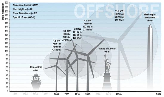
Figure 1. Expected Growth in Offshore Turbine Size [4].
2. Wind Turbine Vibration—An Overview
The wind turbine structure has several degrees of freedom; the tower can bend in the longitudinal and lateral directions; the nacelle and rotor can translate and rotate in tilt and roll, respectively; and bending of the blade can occur in flapwise (out-of-plan) or edgewise (in-plane) directions [8], as shown in Figure 2.
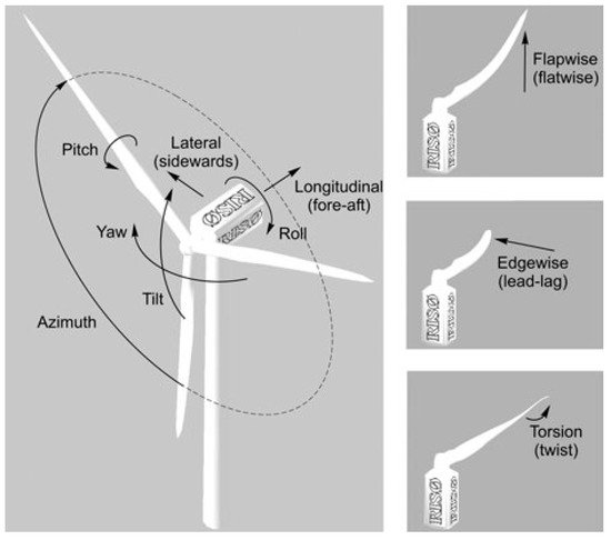
Figure 2. Degrees of freedom of wind turbine [8].
The vibration of the wind turbine is a very complex, multi-coupling phenomenon. Several types of vibrations affect the wind turbine. Nevertheless, the most important ones are those of the blade that contribute and propagate to the other components as the mechanical transmission chain and the tower. Multiple loads induce blade vibrations [7]:
-Wind turbulence;
-Wind shear;
-Gravity;
-Tower shadow;
-Mass and aerodynamic imbalances; and
-Wake effects.
These unsteady loads might lead to blade structural resonance, fatigue damage, lifetime reduction, and could contribute to possible structural failure [7].
The tower vibration originates from the coupled wind–rotor–tower system, mechanical transmission twist vibration, and rotor rotation [9], resulting from the loads, as mentioned above. Additionally, the effect of the waves for offshore wind turbines should be considered
Wind turbine vibrations might represent a potential threat to the environment, community/business interests, and land itself [10].
Rezaeiha et al. [7] quantified the relative contribution of each of the sources mentioned above on the total fatigue loads. They showed that over 65% of flapwise fatigue, results from wind turbulence, while gravity contributes to over 80% of edgewise fatigue.
3. Vibration Control Systems
Numerous vibration control systems are described in the scientific literature, many of which were adapted from other fields like aeronautics or civil engineering to fit wind turbine applications.
There are significant differences between aeronautical and wind turbine applications: different operating conditions, maintenance requirements, size, and weight of the blades. Although the unsteady environment is similar to a certain extent, wind turbines are subject to some other complicated effects like wind shear, turbulence, tower shadow, and wakes of the neighboring turbines. On the other hand, the loads acting on helicopter blades (mostly in forward flight) are periodic, due to the high variances in both the local angle of attack and the relative velocities seen by the blade sections during one revolution [11].
The different control systems belong to six main categories, based on their operating mode:
-Advanced Blade Pitch Control
-Variable rotor diameter
-Flow control
-Tuned mass damper
-Active tendons
-Piezoelectric materials
3.1. Advanced Blade Pitch Control
Most modern wind turbines use the variable speed topology and collective pitch control to maximize energy production in the regimes beyond the rated speed. Moreover, advanced blade pitch control methods alleviate blade loads:
-
Cyclic pitch control—a phase shift of 120° applies to blade pitch angles [12] and helps reduce the effect of gravity loads.
-
A tiny increase of blade pitch angle reduces loads over the tower in the far aft direction, caused by wind turbulence, as proposed in [9]. This method was studied numerically and showed a good reduction of tower vibration in the far aft direction, with little impact on the power generated [9].
-
Individual pitch control—this method was proposed by Bossanyi et al. [13] to optimize the performance of the wind turbine and for load reduction. It consists of individually controlling each blade’s pitch angle, using local blade measurement. Bossanyi validated the idea and proved in [14] that a significant load reduction resulted from the use of an LQG controller. The fatigue load reduction obtained using an industrial PC was later quantified [15][16][17] to 20–40%. A test field [18] demonstrated that the load reduction of the blade root moment above the rated speed was 20–25%. Other research compared this method, where control is based on inflow measurements (angle of attack and relative velocity), with traditional collective and cyclic methods for fatigue load reduction and generated power [19]. The results showed a reduction of 25% of flap load and 9% of shaft load using this method, with a small reduction of power of 0.2% over 20 years, as compared to 1.3% using the cyclic method.
3.2. Variable Rotor Diameter
The Variable Rotor Diameter (VRD) method consists of increasing the blade length to capture more energy in low-speed and reducing it to minimize loads in high-speed regimes [12]. Two different designs of the VRD were proposed. The first, known as S-VADER (where “S” refers to sliding), utilizes an external section of a blade that can contract/retract telescopically into the main section blade [20], as shown in Figure 3. The second, known as C-VADER, changes the swept area of the rotor by coning the blade [21].
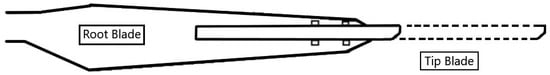
Figure 3. Illustration of variable rotor system [6].
This system is designed to improve the power coefficient rather than for vibration control. It faces considerable challenges for full-scale wind turbines—sophisticated control, increased weight, and difficulty in maintaining the aerodynamic efficiency of the blade [12].
3.3. Flow Control
The flow control was successfully applied to control loads of wind turbine blades, aircraft wings, rotorcrafts, and gas turbines. Most flow control devices use the concept of the smart rotor that involves distributed actuators and sensors controlled by a microprocessor. This analysis collected data from sensors and used the control law algorithms to command the actuators and adapt a system response [22].
The purposes of flow control are either:
-To prevent/promote flow separation by changing the airfoil shape and modify the lift coefficient, as shown in Figure 4a.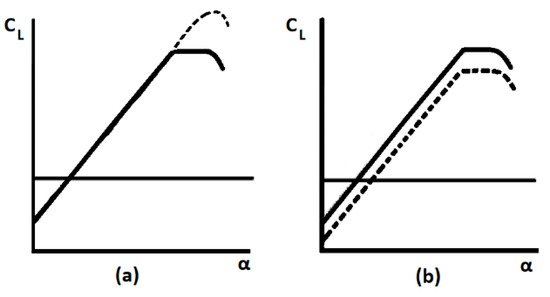
Figure 4. Effect of flow control devices on the airfoil lift curve. The solid line is the original airfoil; the dashed line is an airfoil with a device. (a) Delay stall devices and (b) camber modification devices [23].
-To delay/advance the transition of flow from laminar to turbulent and inversely, as shown in Figure 4b, by varying the active chord of the blade and thus changing the Reynolds number.
-To suppress/enhance turbulence and to reduce/augment the flow mixing in the boundary layer.
As a result, the flow control help to reduce drag, increase lift and flow mixing, and contribute to flow-induced noise reduction [12].
Most flow control systems originated from the aircraft industry and were adapted to wind turbines. For some of these devices, we describe their operating principle, and identify their advantages and drawbacks for wind turbine applications.
3.3.1. Trailing-Edge Flaps
The concept of trailing edge flaps is to use a small movable surface to directly control the blade lift. The deployment of this surface on the pressure side increases the lift coefficient. On the contrary, the implementation on the suction side decreases the lift coefficient [12][11]. This technique was inspired by existing technology in aircraft and rotorcraft applications [24]. The first helicopter with blades equipped with piezoelectric driven trailing edge flaps (as shown in Figure 5) was tested at full scale in 2005, which demonstrated a remarkable vibration reduction in open and closed-loop mode [25]. There are several types of trailing edge flaps:
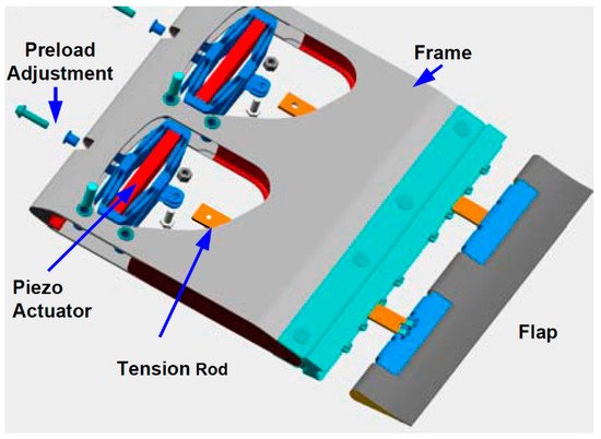
Figure 5. Helicopter blade with flap unit assembly [25].
- -Traditional trailing edge flaps—also known as ailerons (
-
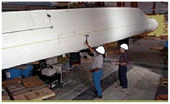
Figure 6. Wind turbine blade with a traditional trailing edge flap [23].
-
-Non-traditional trailing edge flaps. These are of different types:
-
(a)
-
Compact trailing-edge flaps—these flaps have a compact design with small actuators embedded inside the blade to quickly move a tension rod that deflects the flap [12], like the device shown in Figure 5. There are different types of compact flaps:
-
-Rigid flaps with a flatform and no curve; these flaps were simulated in [26] using FAST code and showed a blade load and tip deflection reduction of 8 to 24% over different wind regimes.
-
-Soft curved flap.
-
-Highly curved flap.
2D studies showed that the curved flap is aerodynamically more efficient than others, despite the slight increase in the flap hinge moment [27][28]. It could reduce the standard deviation of the normal force by 81–95%, depending on the case [29].
-
-
(b)
-
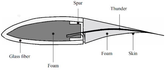
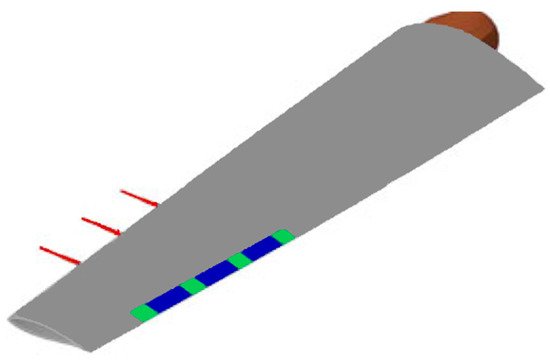
Adaptive trailing edge geometry—this is a flap with no hinges, made of piezoelectric actuators attached to the main airfoil and shaped with soft foam to give them an aerodynamic shape. The foam is covered with skin to provide a smooth surface, as shown in Figure 7 [30]. Ferede et al. [31] accomplished an analytical study for the NREL 5 MW wind turbine, equipped with a camber morphing blade tip applied to the outer 30% of the blade span.
This system reduced fatigue loads and blade tip displacement under different charges, applied according to IEC standards. Andersen et al. [32] investigated the optimal position of the flaps and the gauge sensor, in addition to the number of flaps applied to the NREL 5 MW wind turbine.
Additionally, these flaps were experimentally tested [33] and were found to reduce up to 90% of the load. Moreover, its application to a full-scale Vestas V27 wind turbine, as shown in Figure 8, demonstrated an apparent load reduction, despite only 5% of the blade span being covered with an active trailing edge flap.
-
(c)
-
Adaptive compliant wings—this concept was first proposed by Kota et al. in [34][35] for aircraft applications. A compliant wing is a flexible one-piece structure with no hinges, which can transfer movement and power through its elastic deformation. Not only is it flexible enough to deform, but it also has enough rigidity to withstand external loads [24][36].
-
3.3.2. Microflaps
These are small flaps of height in the order of boundary layer thickness (1–2% of the chord) that can rotate 90° in both directions [12]; as shown in Figure 9. Van Dam et al. [12] conducted computational studies on the transient aerodynamic effect of the microflaps and microtabs on the lift and drag coefficient. They concluded that the microflaps have a slightly faster response time and more substantial effectiveness with a slight increase of bluff-body vortex shedding [38]. A subsequent study by Chow et al. [39] confirmed these results.
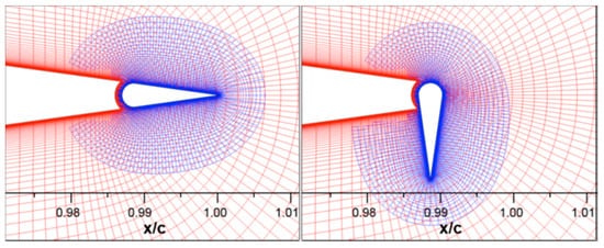
Figure 9. Schematic of microflap in retracted and fully deployed position [36].
All previous types of flaps proved promising for lift enhancement, with minimal drag production. Nevertheless, additional studies are needed to assess the weight, dynamic response, and power required to achieve load reduction. On the other hand, these systems have several drawbacks, including scalability to large models, durability in long-term use, and reliability of the deployment devices [12]. There is a concern with the complexity of installing the actuators, especially near the blade tip, with a small chord.
3.3.3. Microtabs
These are small tabs located near the trailing edge, as shown in Figure 10. Introduced by Yen et al. in the early 2000s [40][41], they are inspired by the Gurney flap, presented by Liebeck in 1978 as a method to increase the lift with an affordable drag penalty, if the flap was in the order of 1–2% of the chord. As with the trailing flaps, the deployment of the tab perpendicular to the airfoil on the pressure surface, enhanced the lift; while using it on the suction surface, reduced the lift [12]. Thus, controlling the position of the tab helped reduce the airfoil vibration.
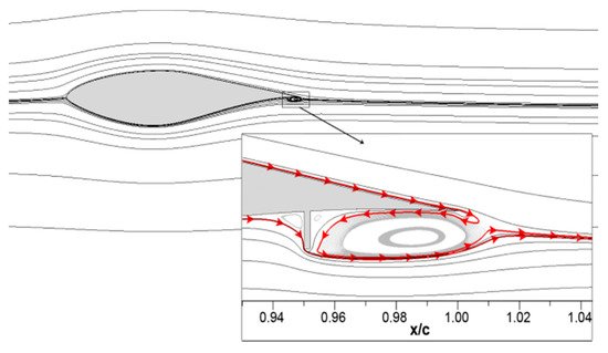
Figure 10. Microtabs schematic located at 95% of chord [37].
The optimal tab height and position, investigated in [40], were 1% of the chord located at x/c = 95% on the lower surface of the airfoil; the lift increased by 30–50%, both in numerical and experimental tests, with limited drag. Several studies, ranging from CFD simulations to wind tunnel experiments, demonstrated the effectiveness of these tabs in static and dynamic regimes [41]. Chow et al. [42] studied the efficiency of such a system in a transient regime, with a moderate change of angle of attack and varying deployment time. Mayda et al. [43] studied the effect of tab gaps on the aerodynamic load alleviation, using a 3D numerical model. They concluded that the addition of gaps reduced the drag induced by the full tab and ensured a compromise between lift and drag.
The appealing features of this method include [12][44] small size, fast activation, mechanical simplicity, low power requirements, and short linear perpendicular deployment distance, which induced small forces for a given change in sectional lift.
On the other hand, microtabs used for wind turbines might result in noise generation [45], air leakage generating aero-acoustic noise, vulnerability to moisture, and dirt [44]. Another problem is the complexity of installation due to the limited space inside the far aft position of the tabs [12][44].
3.3.4. Miniature Trailing-Edge Effectors (MiTEs)
MiTEs, similar in principle to the microtabs, are small trailing edge devices, approximately 1–5% chord in height with a width less than five times their height [46]; as shown in Figure 11. They help to produce a region of separated flow directly upstream of the flap, and thus change the Kutta condition of the flow [12]. Their design with a proper activation system, as proposed in [47], gives three control possibilities—positive (flaps on the pressure side), negative (flaps at the suction side), and neutral (flaps at the neutral position).
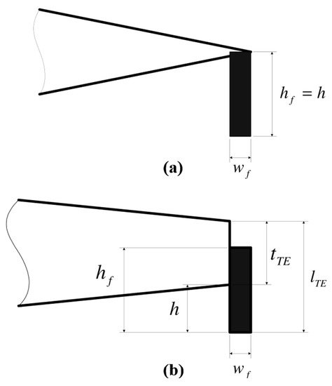
Figure 11. Geometry of MiTEs attached to (a) sharp and (b) blunt trailing edge [48].
This system was designed originally for aircraft applications. The steady-state/dynamic aerodynamic response of these effectors was studied using 2D computational analysis [48], CFD simulations, and a wind tunnel for aircraft [49], helicopters [50], and flight vehicles [51].
The appealing features of such a system include:
-
-Small size and low inertia of effectors that allow them to operate at very high frequencies with very low actuators loads [50].
-
-A large number of these effectors make the system fault-tolerant and can be manufactured at low cost since the devices are digital, eliminating the need for expensive, accurate, and high-rate servo-actuators [49].
-
-No need for slots in the blade construction due to the far aft location of these effectors [12].
However, this system requires a mandatory blunt trailing edge, which decreases the performance of the wind turbine when the system is not activated and increases noise in the tip region [12].
3.3.5. Synthetic Jets
One of the methods to achieve flow separation control is acoustic streaming, initially studied and designed for aerospace airfoils. It uses an acoustically driven cavity submerged in the airfoil, to excite the boundary layer through a small rectangular orifice placed near the leading edge [52]. The application of this method delayed flow separation at different angles of attack and the Reynolds number; as shown in 2D simulations and wind tunnel tests [52][53][54][55]. Another approach considered an oscillating boundary or a diaphragm with proper actuation frequency [56]; as shown in Figure 12. This method is a net-zero mass flux; i.e., it can transfer momentum to the flow without net mass injection across the flow boundary [57]. The jets interact with the boundary flow by displacing streamlines and leading to a modification of the aerodynamic shape of the bluff bodies [12]. The tests in a wind tunnel over a small blade (Figure 13) show that the flow was either fully or partially re-attached, depending on the angle of attack and the Reynolds number, thus, reducing vibrations [58]. Moreover, in [59], this system was tested over a beam using three sets of actuators for 14 total synthetic jets distributed in three groups—one near the root, one in the middle, and one at the tip. Tests in the wind tunnel were conducted over a range of angles of attack and Reynolds number, and showed that the actuation near the tip had the most influence for flow reattachment and vibration mitigation.
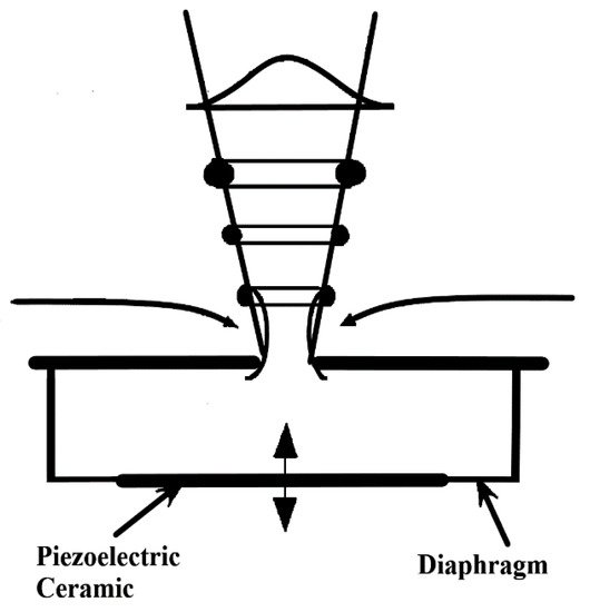
Figure 12. Schematic side view of a synthetic jet actuator [60].
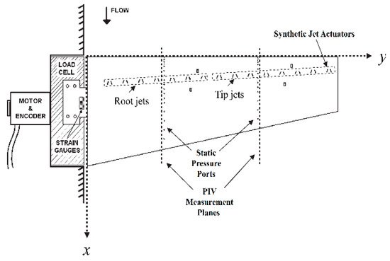
Figure 13. Schematic of the mounting and configuration of synthetic jets for the wind turbine blade model [58].
Van Dam et al. [12] detailed the pros and cons of such a system. It can be easily integrated into the aerodynamic surface, has a reduced weight, and requires minimal power, as small actuators are needed. The location of jets at approximately 20% of the chord, slightly away from the leading edge, diminishes the problems caused by airfoil modifications. On the other hand, the jet cavities might interfere with the flow patterns of the free stream when the device is inactive, thereby causing noise and performance reduction. Additionally, dirt and ice can obstruct the cavity.
3.3.6. Vortex Generators
There are three types of vortex generators:
-
-Solid-vortex generators.
-
-Vortex generator jets (VGJ).
-
-High-frequency micro-vortex generators (HiMVG).
3.3.6.1.Solid-Vortex Generators
The solid-vortex generators (SVGs) were first examined by Taylor et al. [61] as a method to reduce flow separation. These are solid tabs of specific geometry mounted on the airfoil surface near the leading edge, as shown in Figure 14. Several studies explored the efficiency of this device as a method to improve the performance of a wind turbine. The numerical analysis highlighted [62][63][64][65][66] that the lift coefficient increased by up to 17% [64], flow separation was reduced [65], and the stall was delayed. The effect of the size of SVGs on both lift and drag was studied in [63]. Additionally, a wind tunnel experiment showed an increase of lift coefficient up to 0.34 with a significant drag penalty when using SVGs [67], and an excellent capability to delay or eliminate stall and bifurcation [68]. Thus, while SVGs do not actively reduce vibrations, they help eliminate vibrations associated with flow separation. Other experimental studies in a wind tunnel show the attractive effect of this device [69]; the optimal chordwise position of these SVGs is in the range of 15–20% of the chord, with a smooth lift increase and low drag penalty [70].
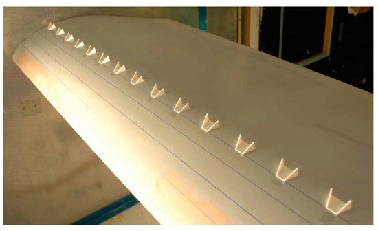
Figure 14. Solid Vortex Generator configuration mounted on the surface at 20% of the trailing edge [70].
3.3.6.2.Vortex Generator Jets
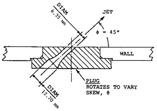
Wallis et al. studied vortex generator jets as early as the 1950s [71][72]. Similar in principle to synthetic jets, they are small jets that blow through holes in the airfoil surface (as shown in Figure 15). They generate longitudinal streamwise vortices in the boundary layer, leading to an increase in cross-stream mixing of streamwise momentum, and thus, they delay the stall [73]. This system, experimented in pulse mode at a frequency range between 10 and 100 Hz, proved a drastic reduction of boundary layer separation on the suction side, in addition to a 60% reduction in wake losses [74]. Additional research demonstrated that this system reduced flow separation and quantified the energy consumption for increasing Cl; an exponential jet injection instead of a constant jet reduced energy consumption by up to 14% [75].
Vortex generator jets can be controlled and are easy to install near the leading edge, where the airfoil is thicker [12]. These eliminate the disadvantages of solid fixed VGs but increase the complexity and cost due to compressed air lines embedded in the blade and slots [12][73]. However, the jet orifice is subject to obstruction by dirt, ice, and insects [12].
3.3.6.3. High-Frequency Micro-Vortex Generators
These devices are low profile, sub-boundary-layer scale vortex generators (VGs) [76]. They are solid small active tabs of specific geometry embedded into the airfoil surface and activated with an actuator to deploy and retract with a high speed; as shown in Figure 16 [62].
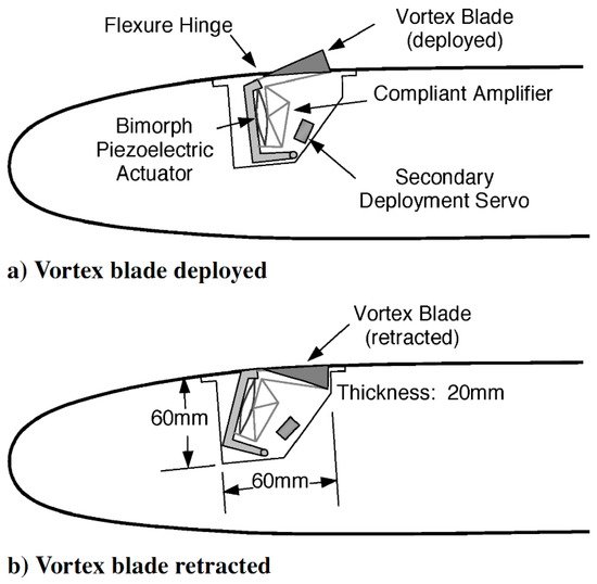
Figure 16. High-frequency micro-vortex-generator schematic [62].
The solidly fixed vortex generators have the advantages of small size, low cost, simplicity, and roughness [73]. The main disadvantage of the fixed device is that it cannot provide active vibration control—the main function being to delay stall [12]. Additionally, they add parasitic drag when stall suppression is not needed [73]. Active VGs avoid these drawbacks as they retract and deploy based on flow conditions. Active VGs increase complexity and cost, and the slots are needed to install these devices that generate noise [12].
High-frequency micro vortex generators have many advantages, such as their small size, lightweight, controllability, and ease of installation, without the need for compressed air lines in the blade. On the other hand, noise generation and performance reduction are a concern, as a slot is required to place the devices [12].
3.3.7. Plasma Actuators
Plasma actuators received a great deal of attention over the last 20 years as a method of flow control, by manipulation of the ionic wind created by applying a voltage between electrodes [77]. This system consists of at least two electrodes integrated into the wing surface, to which a high voltage is applied [78]. When the voltage is applied, the ions repel from the vicinity of the high voltage electrode [79], creating the so-called electric wind that appears blue, modify the boundary layer airflow, and delay the separation [12]. The system originated in 1950, but since 2000, several scientific teams are working on this topic all over the world [78]. There are four different configurations for plasma actuators, as explained by Moreau et al. [78]:
-
-Corona discharge
-
-Dielectric barrier discharge (DBD)
-
-Sliding discharge
-
-Wall jet
The Corona discharge actuator was the first plasma actuator studied as a method of creating an electric wind, as tested by Robinson in 1960 [79]. The ASTM Standard Method for Detection and Measurement of Discharge Pulses in Evaluation of Insulation Systems defines corona discharge as “a type of localized discharge resulting from transient gaseous ionization in an insulation system when the voltage stress exceeds a critical value” [80].
The actuator consists of two electrodes of several geometric possibilities placed inside a groove at the wall surface; as shown in Figure 17. These electrodes face each other on the same side of a dielectric surface [81]. To increase the energy of the electric field at the anode, its diameter must be lower than the cathode [78].
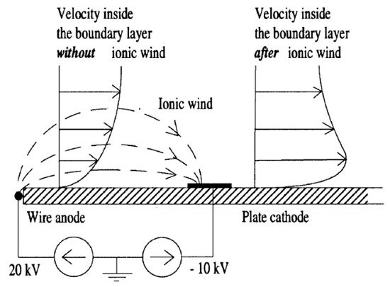
Figure 17. Schematic view of the corona discharge actuator with visualization of the impact of ionic wind over the boundary layer airflow [82].
This method was used for flow control. It successfully contributed to the reattachment of detached flow, with a mean electric wind flow velocity of about 1 m/s, at a high angle of attack and Reynolds number [83]. Moreau et al. [84] obtained results similar to those presented in Figure 18. They found that the ionic wind velocity could reach about 3 m/s with an increase in the discharge current. This Electro-Fluid-Dynamic (EFD) actuator system reduced drag up to 30% at a flow rate of 10 m/s. While the corona discharge actuators mainly use DC voltage, a new kind of actuation proposed by Messanelli et al. [85], is based on a positive waveform with a given frequency f applied to multiple triangular tips. This method leads to considerable improvement in the operability of these devices.
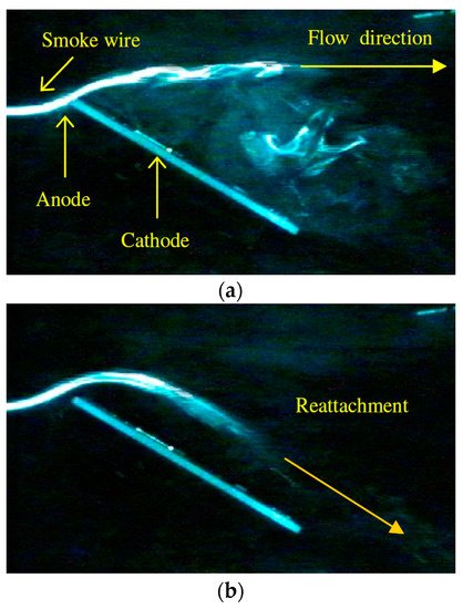
Figure 18. Visualization of the airflow at 0.4 m/s with DC corona discharge actuator off (a) and actuator on (b) [84].
The DC corona discharge system presents specific problems due to its dependence on several factors, such as surface cleanliness and air humidity. It has stability problems due to the disruptive electric arc risk [81].
The performance of corona and DBD actuators depends on multiple parameters like the diameter of electrodes, the nature of the insulating surface between electrodes [86], dielectric thickness, voltage waveform [87][88][89], the gap between electrodes [86][89], excitation frequency [88][89][90], and voltage slew rate [87].
3.3.8. Active Twist
This device operates by twisting the whole blade or the outer part over its span. As a result, the angle of attack changes throughout the blade, with the biggest changes at the tip. This concept uses actively controlled bending-torsion or tension-torsion coupling, and is actuated through an embedded anisotropic fiber composite material [11]. This method was applied to wind turbines by Karaolis et al. [91], using biased lay-ups in blade skin to achieve blade twist. Analytical simulations showed significant fatigue damage reduction of up to 80% using this method [91].
The challenges associated with this concept are the slow response due to relatively large inertia and the high power required [34]. Additionally, the aerodynamic efficiency decreases due to alteration of the optimal aerodynamic profile of the blade. The actuator and manufacturing requirements increase the cost and reduce blade stiffness [12].
3.3.9. Shape Change Airfoil
This system works by physically changing the shape of an airfoil. The piezoelectric material embedded in the upper surface [12][11][24] rapidly deploys and retracts to adjust the airfoil camber; as shown in Figure 19. Additionally, the deployment generates vortices that delay separation.
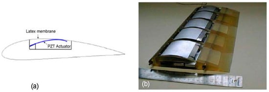
Figure 19. Schematic (a) and model (b) of the adaptive wing [92].
Computational and experimental studies assessed this technique’s potential. The shape change airfoil has a smooth deployment area. There are minimal problems associated with noise generation and performance reduction due to dirt accumulation. The most significant hurdle with this concept is that the piezoelectric material covers a large part of the chord.
3.3.10. Active Flexible Wall
The system detects the beginning of the boundary layer separation and generates minor disturbances into the boundary layer, along the leading edge. The device consists of an array of transducers mounted inside a flexible housing comprised of an inner wall and an outer wall (Figure 20). This unit can work in two modes—sensor mode and actuator mode. The system detects the occurrence of flow separation in the sensor mode and then the actuator mode induces outer wall vibration to reduce boundary layer separation [93].
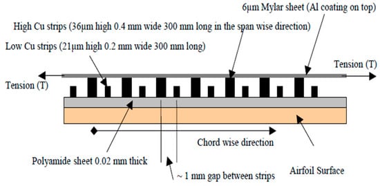
Figure 20. Schematic of an active, flexible wall transducer [94].
This system is added to the existing blades without significant modifications, has low power requirements, does not affect the flow due to the smooth outer surface, and can operate in both sensor and actuator mode. On the other hand, the location near the leading edge might cause problems if the device is soiled or damaged [12].
3.4. Tuned Dampers (TD)
Tuned dampers are devices attached to the structures to reduce the amplitude of mechanical vibrations, by dissipating the energy. These dampers act in the structure as passive, active, or semi-active devices [95]. The previous vibration control methods only work on the blade itself, either directly (by intervening in the mechanical response of the blade) or indirectly (by changing the aerodynamic performance that affects the overall vibration response of the blade). The tuned dampers control the vibration of the wind turbine by acting directly either on the blade itself, the tower, or the nacelle. There are several types of tuned damper highlighted in the literature, such as:
-
-Tuned mass damper (TMD)
-
-Tuned liquid damper (TLD)
-
-Controllable fluid damper
-
-Tuned rolling balls damper
-
-Pendulum system
Rahmane et al. [95] present a comprehensive review of most vibration control dampers.
3.4.1. Tuned Mass Damper (TMD)
The standard tuned mass damper consists of an auxiliary mass attached to the main structure using springs and dashpot elements, as shown in Figure 21. Typically, this system is installed on the tower, the nacelle, or the blades.
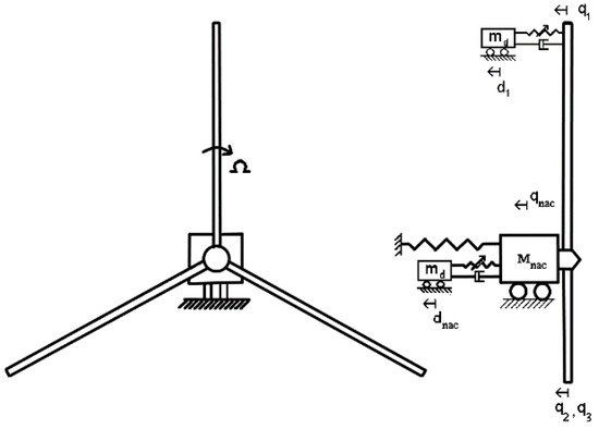
Figure 21. Schematic of a typical TMD for the Tower/Blade interaction vibration [89].
A Passive system predetermined the characteristics for springs and dashpots. These are the simplest devices because they do not need external energy to operate [96]. A semi-active device adjusts these characteristics over time, according to frequency. They provide more flexibility and controllability than the simple passive TMD, but require external power to operate. Active control consists only of a mass and an actuator, which plays the role of both restoring and damping the forces acting on the weight [96]. This system is the most complex compared to others [97].
The spring constant and the damping ratio of the dashpot determine the natural frequency of the tuned mass damper. The parameter adjusted in the tuned mass damper enables the auxiliary mass to oscillate with a phase shift to the motion of the structure.
Analytical and numerical simulations studied the application of passive TMD to offshore wind turbine vibration control [98][99][100][101]. The numerical simulations predicted a reduction of the nacelle sway displacement of up to 50%, when using multiple TMDs [102]. Other studies investigated the active control approach [103][104] and showed up to a 30% load reduction for a floating, barge-type, offshore wind turbine [105].
Fitzgerald et al. [106] proposed a new concept for the active control of in-plane blade vibration, by attaching a cable to the active tuned mass damper on one end and the blade tip at the other end; as shown in Figure 22. The study showed that this method is feasible for in-plane vibration control at higher turbulent loadings.
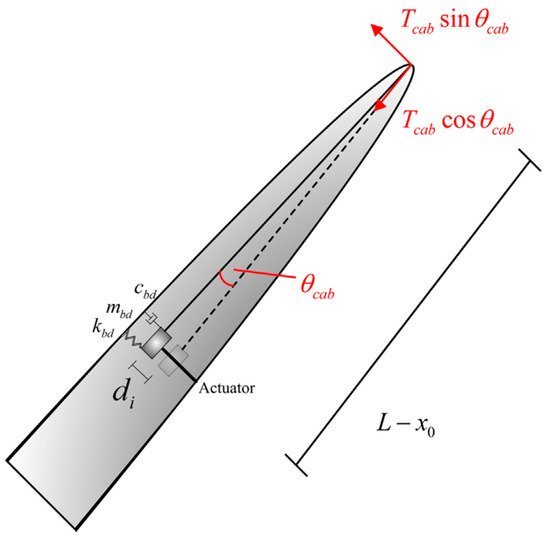
Figure 22. Schematic of the active tuned mass damper with a cable attached to it for in-plane vibration [106].
Semi-active vibration control methodology was applied for tower vibration control in [107]; several configurations were discussed, including different positions of the actuator. The main tower base bending moments were reduced up to 20% in extreme cases, while fatigue loads were reduced by approximately 10%. Other studies highlighted the effectiveness of an inverse velocity-based ground-hook (IVB-GH) controller over the passive device, for an offshore wind turbine in extreme environmental conditions (Ultimate Limit State—ULS) [3]. Moreover, researches demonstrated the effectiveness of a semi-active tuned mass damper for flapwise (out-of-plane) [108] or edgewise (in-plane) vibrations [109].
Tuned mass dampers showed reliability, robustness, and effectiveness in the different applications, as mentioned above. However, they still require additional experimental tests, before extensive use for wind turbine vibration control. There is a significant concern about the considerable mass of this system, which adds an extra load over the whole structure, hence increasing fatigue and reducing the lifespan of the wind turbine.
3.4.2. Tuned Liquid Dampers (TLD)
This method originates in civil applications for vibration control of high-rise buildings [110]. It consists of counteracting the effect of external forces applied to the structure, using a container partially filled with a fluid that acts like a mass damper [111]. Hence, the vibrational energy of the structure is dissipated primarily due to the gravitational restoring force acting on the displaced liquid [112], and secondly, due to head loss of the liquid passing through small orifices opened at the center of the cross-section of the tube; as shown in [112][113].
There are several shapes for the container of tuned liquid damper (TLD):
-
-U shape, as shown in Figure 23—this shape is the most often encountered in the literature. Several analytical calculations demonstrated the effectiveness of this method for blade vibration control [114]. Colwell et al. [112] showed that up to 55% reduction in the peak response occurs with a tuned liquid column damper (TLCD) installed on a floating offshore wind turbine. Lee et al. [113] concluded that the energy dissipated by the TLCD device applied to the tower might reach a value higher than 70%, if the parameters of the actuator are well optimized. Their results from a preliminary experimental test of feasibility prove this effectiveness. While the devices mentioned above were passive ones, a study was conducted by Yalla et al. [115] to examine the efficacy of a semi-active method. This semi-active device is a variable-damping with a controllable valve placed at the orifice, and is subject to a control algorithm. The numerical simulations showed that with negligible power requirements for the valve operation, this strategy further reduced vibrations as compared to the passive ones. This improvement could reach 25–30% in the case of harmonic loading, while for random excitation, it was about 10–15%.

Figure 23. Schematic of the Tuned Liquid Column Damper device [113].
-
-Rectangular shape—this method uses the same principle as the U-shape damper. Nevertheless, the container is a rigid rectangular tank containing fluid to damp the structure oscillations. The system was discussed in the early 1990s by Fujino et al. [116] as a passive mechanical damper to dissipate the horizontal vibrational energy of structures. The idea of this device was adopted by Tong et al. [117], who introduced a damper of an annular rectangular shape (as shown in Figure 24). This device operates as a bidirectional damper for a floating barge, hydrostatic wind turbine. The designed system aimed to reduce the roll and pitch vibration of the barge. The numerical simulations demonstrated the effectiveness of such a system in extreme and normal events, showing a tower base load reduction between 10% and 27.6%, depending on the simulated conditions.
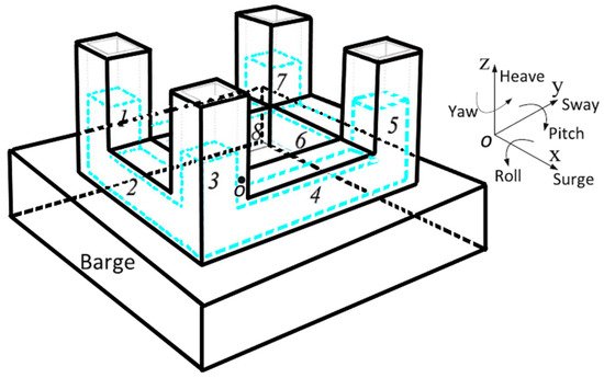
Figure 24. Schematic of the bidirectional horizontal tuned liquid damper located on the barge of a wind turbine [117].
-
-Spherical shape—this damper consists of a spherical container partially filled with liquid. Chen et al. [118][119] studied this type of device composed of two layers of hemispherical containers partially filled with water; as shown in Figure 25. The vibration energy of the structure dissipates with this system via the sloshing of liquid in containers. For maximum efficiency, the sloshing frequency of the liquid is similar to the natural frequency of the wind turbine. The device was tested with horizontal excitations induced by shaking the table as a simulation of overspeed wind, extreme operating gust, and earthquake excitations. The results showed that the system reduced the standard deviation of the dynamic responses with a liquid mass of about 2% of the general structure mass, by over 40%.
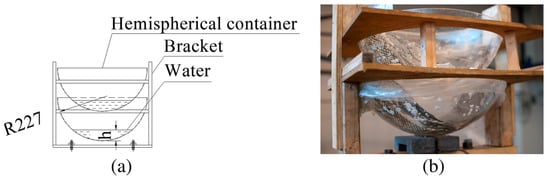
Figure 25. Spherical tuned mass damper in schematic view (a) and the actual system (b) [118].
-
-A crossed-tube like container was proposed by Zhang et al. [120] as a system to control vibration in two directions, but this device is not yet tested on a wind turbine.
Tuned liquid dampers are useful as mentioned above, with more efficiency for TLCD, due to the extra damping added by the presence of the orifice. They can dissipate very low amplitude excitations, unlike tuned mass dampers. Moreover, they are reliable and robust over a wide range of excitation levels [112], easy to install, with low initial and maintainability costs, and do not need to overcome high slip loads like the TMDs [121]. However, there are disadvantages—the significant mass of the system (1–2%) [112] and the reduced covered frequency band since the device is tuned to the natural frequency of the system. Additionally, the position of these actuators in blades needs further exploration. More experimental tests are required to validate the vast amount of numerical simulations.
3.4.3. Controllable Liquid Dampers
Controllable liquid dampers are semi-active control systems that use a magnetorheological (MR), as shown in Figure 26, or electrorheological fluids.
Magnetorheological (MR) fluid dampers use a specific fluid characterized by the presence of a high concentration of soft magnetic particles in a nonmagnetic carrier [122]. This damper is equipped with electrical windings to generate a magnetic field, changing the apparent viscosity of the fluid [123].
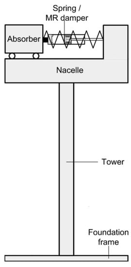
Figure 26. Schematic of the MR controllable liquid assimilated to the nacelle of the wind turbine [123].
The MR damper was first integrated into a wind turbine application by Martynowicz et al. in 2013 [122]. Their research team conducted several studies on magnetorheological-tuned vibration absorbers. They developed a test bench to study this effect on a wind turbine tower and the nacelle replaced by a stiff vertical rod and a block fitted at the top. They proved the efficiency of these devices controlled by different types of controllers—the developed, refined variation of PID showed in [124] and the modified ground-hook control, such as in [123]. These two controllers proved efficiency in the first-order bending mode of vibration of the tower.
Caterino et al. [125] investigated the use of magnetorheological dampers for semi-active control of tower vibration. The actuators are two dampers placed at the bottom of the tower with two springs. One control approach uses the on–off strategy, and another used a closed-loop control with a variable control input. The system was experimented on a 5-m high tower prototype with a concentrated top mass and showed a promising reduction of the base stress and displacement for both strategies.
Sarkar et al. [126] proposed a method to control the tower vibration, using a tuned liquid column damper. They used magnetorheological fluid inside the column instead of water, and windings instead of the original orifice in the “classical” TLCD, as described in Figure 27 [113]. This method overcomes the problems of a regular TLCD operation, such as the difficulty of controlling the orifice opening and the big mass of the water. The magnetorheological fluid is denser than water; thus, it takes less space in the structure. The results obtained with an analytical model showed a reduction that could reach 57% of the RMS of tower displacement in low wind speed (5 m/s); this reduction decreased with an increase in wind speed.
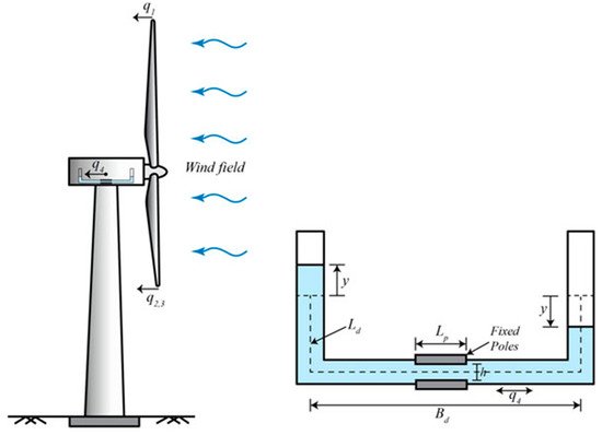
Figure 27. Tuned liquid column equipped with magnetorheological damper [126].
The use of magnetorheological fluids was tested in the University of Québec at Rimouski (UQAR) [127][128] and revealed a reduction of 30% of vibration response. Other researchers [129] studied the vibration suppression using a magnetorheological patch layer bonded to the surface of the airfoil, and controlled with an electromagnetic actuator. The system showed good results but still needs to determine the actuator location and methodology. Therefore, it is impossible to use it for wind turbines in the present configuration.
The main advantages of this system are the fast response, a wide range of resistance forces, robustness from the fact that the fluid is less sensitive to temperature change, and small power requirements [124]. Additionally, this damper is reliable and fail-safe [130].
On the other hand, its mass can reach up to 8.8% of the total system [123], and it requires a massive space in the nacelle, such as in [126] (18 m of liquid length). Additionally, it is challenging to apply to the blade. However, Chen et al. [131] proposed a mathematical model consisting of a magnetorheological damper applied to the blade. The damper controls the edgewise vibration of the wind turbine, but there are no experimental tests to prove the feasibility of the proposed device.
3.4.4. Tuned Rolling Balls Damper
Chen et al. [132] proposed tuned rolling-ball dampers that use multiple steel balls rolling in a spherical container, mounted at the top of the wind turbine, as in Figure 28. The analytical model and experimental validation demonstrated that the use of three balls in each layer could effectively reduce the vibrations of the system. The results from the three cases were:
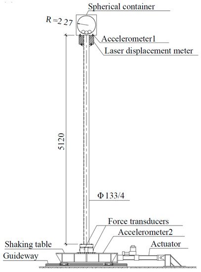
Figure 28. Schematic of tuned roll damper mounted at the top of the tower [132].
-
-56% reduction in top displacement RMS during overspeed;
-
-63% reduction in top displacement RMS during extreme operating gust;
-
-64% reduction in top displacement RMS during parking.
Zhang et al. [133] proposed a method to mitigate edgewise vibrations of the wind turbine blades using a roller damper. It consisted of either a ball, cylinder, or a flywheel with two small rail wheels placed on the rails, to guide its movement. The system sits in the blade at a distance of 2/3 from the top region. The characteristics of the damper, like the mass, the natural frequency, the rolling friction coefficient, and the mounting position, were optimized to reduce vibration. Analytical calculations showed that the system could reduce the standard deviation of the edgewise tip displacement up to 28.26%.
Tuned rolling-balls in a spherical container have the advantage of being multidirectional, as compared to the other tuned damper. It reduces vibrations significantly, is not affected by large tower rotations, and has a smaller weight [132].
On the other hand, this system does not have a wide range of applicability, as it is tuned to one frequency. The roller damper requires additional experimental tests to prove its feasibility, especially the one installed inside the blade. Moreover, the rails erosion problem and the difficulty of maintenance of the system inside the blade, should be considered.
3.4.5. Pendulum-Tuned Mass Damper
The pendulum vibration absorber was one of the first systems to mitigate the vibration of slender high-rise buildings. The Pendulum-Tuned Mass Damper (PTMD) was recently applied to the wind turbine system for vibration control, as shown in Figure 29. To mitigate vibration, the PTMD adjusts to the frequency of the structure by modifying the pendulum length [134][135]. Several analytical models developed for this system demonstrate its vibration reduction capability. Sun et al. [135] compared the effectiveness of PTMD to a dual-tuned mass damper. They showed a reduction of RMS response of around 12% in the case of PTMD, when the mass ratio of the system was 2%.
The advantages of such a system are the simplicity of installation and maintenance [135], and the right increase of the wind turbine’s tower fatigue life, which can reach up to 50% when compared with dual TMDs [136]. On the other hand, the system needs additional experimental validations to prove its effectiveness, and there is a concern about the space required for the pendulum arm. This space reaches 3 m, as revealed by Sun et al. [135] and up to 30 m, which is unrealistic; as shown in [134].
3.5. Active Tendons
A new approach of controlling edgewise vibrations of the blade was proposed by Staino et al. [137], with a system consisting of tendons and actuators embedded inside the blade, as shown in Figure 30. The system reduced the maximum blade displacement by 65%, when applying a force of about 28% of the blade weight. Staino et al. continued their research in [138] and updated their previous model of the wind turbine to consider the effect of variable speed in the vibration response of the system.
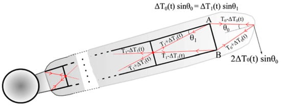
Figure 30. Schematic of the blade with embedded active tendons [138].
The edgewise vibration control using active tendons with an appropriate LQR controller showed promising results. Tao et al. [139] noticed a unique role of the active tendons at cut-out wind speed, when the braking system was activated to stop the rotor, at the expense of control, force increased at 43.1% of the blade weight, putting it under severe vibration. The system reduced maximum displacement by 44.2%.
The advantage of such a system could be resumed by its effectiveness in vibration control; as shown above. On the other hand, it acts only on the edgewise vibration and cannot be retrofitted, as the tendons should be embedded in the blade structure. Additionally, there is concern about maintenance and leakage of actuator oil from the conduits and the need for a considerable actuator force. Considering all these elements, Staino et al. [140] proposed a dual system based on an active tendon actuator combined with passive pitch control, to reduce the control force demand for tendons and improve the overall effectiveness of the system. The system needs experimental tests to prove its effectiveness.
3.6. Piezoelectric Actuators
Piezoelectric materials can transform mechanical energy into electric energy and vice-versa, based on a phenomenon named the direct (and reverse) piezoelectric effect, as shown in Figure 31 [141]. Piezoelectric transducers are widely used in structural vibration control applications, due to their excellent actuation and sensing abilities [141].
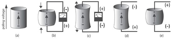
Figure 31. Different reactions of a poled piezoelectric element to the applied stimuli: (a): direction of polarization of the poled piezoelectric ceramic element, (b,c) direct piezoelectric effect, (d,e) reverse piezoelectric effect [141].
There is a limited number of studies about the application of piezoelectric material in the vibration control of wind turbines. Lui et al. [142] proposed the use of a piezoelectric patch embedded in the host composite, near the leading edge. He used analytical and numerical simulation to validate this solution under extreme conditions, using the LQG (Linear Quadratic Gaussian) controller. The results were excellent and promising, but experimental validation is needed. Yin-Hu Qiao et al. [143] proposed a new wind turbine blade layout, composed of the main beam (rigid foam or Balsa wood) and skin (glass fiber reinforced plastic GFRP layers) with piezoelectric wires integrated into the skin; as shown in Figure 32. They used numerical analysis with the finite element model, but no numerical result was shown to justify their configuration.
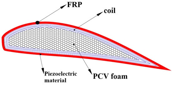
Figure 32. Schematic of the new blade layout with piezoelectric wires [143].
An extensive literature review showed that piezoelectric materials serve for vibration control of cantilever plates [141][142][143][144][145][146][147][148][149][150][151][152][153][154][155][156][157][158][159][160][161][162][163][164], which are a good approximation of the blade structure. The piezoelectric element can act both as an actuator and a sensor. Many of these studies use a collocated actuator/sensor; the sensor captures any strain variation in the structure and transforms it into an electric signal sent to the controller that calculates the appropriate feedback, then amplifies and transfers it back to the actuator. This technique of collocated position eliminates the phase delay between the sensor and the actuator [151][155][161][162]. Others use a non-collocated sensor, as in [150], and introduces a phase delay.
For all systems mentioned above, several parameters affected the performances of the piezoelectric system:
-
-Type of control.
-
-Control laws.
-
-Position of Actuator/Sensor.
3.6.1. Type of Control
The vibration control system using piezoelectric material can use a passive, active, or hybrid control.
In a passive system or Shunt Damping, a tuned R-L-C circuit is connected to the piezoelectric poles, as shown in Figure 33. Each branch of the circuit (of indices 1, 2, …) is tuned to damp a specific vibration mode of the plate. Shunt damping has several advantages and disadvantages compared to active control. It does not require a sensor or an electric source, but its performance is sensitive to the exciting frequency with a small effective bandwidth [154].
Figure 33. Schematic of the passive control strategy using the piezoelectric material.
An active system uses an electric source to feed the actuator (Figure 34). It is the most frequently used strategy because of its excellent vibration suppression performance, despite its need for a relatively large amount of power supply.
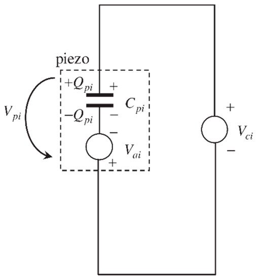
Figure 34. Schematic of the purely active control feedback.
A hybrid system uses a combination of an active and passive circuit mounted in series, as shown in Figure 35. This system combines the advantages of both passive and active approaches, where the shunt network dissipates the energy, and the electric source suppresses vibration [154].
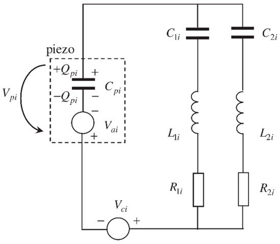
Figure 35. Hybrid system [154].
3.6.2. Control Law
The control law used to activate the piezoelectric actuator plays a crucial role in vibration control. The different control laws used in the literature are:
3.6.3. Position of the Actuator/Sensor
The location of both actuator and sensor influences the plate vibration control. Based on [158], there are six criteria for the optimal placement of piezoelectric sensors and actuators:
-
-The modal forces/moments applied by piezoelectric actuators;
-
-The deflection of the host structure;
-
-The control effort or the energy dissipated;
-
-The degree of observability; and
-
-The degree of controllability.
Bruant et al. [164] determined the optimal position of actuator and sensors using a genetic algorithm that maximizes controllability and observability. Qiu et al. [163] used the H2 norm, based on the same objective. A genetic algorithm was also used in [162] to determine the optimal position of the actuator/sensor. At the same time, COMSOL simulations served to conduct a parametric sweep in [157].
The advantages of the piezoelectric-based systems are low power consumption, fast response, small saturation strains, lightweight, flexibility [11], and the possibility to retrofit the blade. On the other hand, this method needs a lot of research and experimentation to prove its effectiveness in full scale, with massive masses to control.
This entry is adapted from the peer-reviewed paper 10.3390/en14113058
References
- Fronk, B.M.; Neal, R.; Garimella, S. Evolution of the Transition to a World Driven by Renewable Energy. J. Energy Resour. Technol. 2010, 132, 021009.
- Global Wind Energy Council. Global Wind Report; Global Wind Energy Council: Brussels, Belgium, 2017.
- Park, S.; Lackner, M.A.; Cross-Whiter, J.; Tsouroukdissian, A.R.; La Cava, W. An Investigation of Passive and Semi-Active Tuned Mass Dampers for A Tension Leg Platform Floating Offshore Wind Turbine in Uls Conditions. In Proceedings of the ASME 2016 35th International Conference on Ocean, Offshore and Arctic Engineering, American Society of Mechanical Engineers Digital Collection, Busan, Korea, 19–24 June 2016.
- Wiser, R.; Hand, M.; Seel, J.; Paulos, B. Reducing Wind Energy Costs through Increased Turbine Size: Is the Sky the Limit? Lawrence Berkeley National Laboratory: Berkeley, CA, USA, 2016.
- Caduff, M.; Huijbregts, M.A.J.; Althaus, H.-J.; Koehler, A.; Hellweg, S. Wind Power Electricity: The Bigger the Turbine, The Greener the Electricity? Environ. Sci. Technol. 2012, 46, 4725–4733.
- Veers, P.S.; Ashwill, T.D.; Sutherland, H.J.; Laird, D.L.; Lobitz, D.W.; Griffin, D.A.; Mandell, J.F.; Musial, W.D.; Jackson, K.; Zuteck, M.; et al. Trends in the Design, Manufacture and Evaluation of Wind Turbine Blades. Wind Energy 2003, 6, 245–259.
- Rezaeiha, A.; Pereira, R.; Kotsonis, M. Fluctuations of angle of attack and lift coefficient and the resultant fatigue loads for a large Horizontal Axis Wind turbine. Renew. Energy 2017, 114, 904–916.
- Hansen, M.H. Aeroelastic instability problems for wind turbines. Wind Energy Int. J. Prog. Appl. Wind Power Convers. Technol. 2007, 10, 551–577.
- Qiao, Y.; Han, S.; Deng, Y.; Liu, Y.; Dong, J.; Pan, L.; Li, R.; Zhao, B. Research on variable pitch control strategy of wind turbine for tower vibration reduction. J. Eng. 2017, 2017, 2005–2008.
- Dean, W.D. Wind Turbine Mechanical Vibrations: Potential Environmental Threat. Energy Env. 2008, 19, 303–307.
- Barlas, T.; van Kuik, G. Review of state of the art in smart rotor control research for wind turbines. Prog. Aerosp. Sci. 2010, 46, 1–27.
- Johnson, S.J.; Baker, J.P.; van Dam, C.P.; Berg, D. Active Load Control Techniques for Wind Turbines; Sandia National Laboratories: Albuquerque, NM, USA, 2008.
- Bossanyi, E.A. The design of closed loop controllers for wind turbines. Wind Energy Int. J. Prog. Appl. Wind Power Convers. Technol. 2000, 3, 149–163.
- Bossanyi, E.A. Individual blade pitch control for load reduction. Wind Energy Int. J. Prog. Appl. Wind Power Convers. Technol. 2003, 6, 119–128.
- Bossanyi, E. Developments in Individual Blade Pitch Control. In The Science of Making Torque From the Wind; IOP Publishing: Bristol, UK, 2004.
- Bossanyi, E.A. Further load reductions with individual pitch control. Wind Energy Int. J. Prog. Appl. Wind Power Convers. Technol. 2005, 8, 481–485.
- Bossanyi, E.; Wright, A. Field testing of individual pitch control on the NREL CART-2 wind turbine. In Proceedings of the European Wind Energy Conference, Marseille, France, 16–19 March 2009.
- Bossanyi, E.A.; Fleming, P.A.; Wright, A.D. Validation of Individual Pitch Control by Field Tests on Two- and Three-Bladed Wind Turbines. Ieee Trans. Control. Syst. Technol. 2013, 21, 1067–1078.
- Larsen, T.J.; Madsen, H.A.; Thomsen, K. Active load reduction using individual pitch, based on local blade flow measurements. Wind Energy Int. J. Prog. Appl. Wind Power Convers. Technol. 2005, 8, 67–80.
- Jamieson, P.M.; Hornzee-Jones, C.; Moroz, E.M.; Blakemore, R.W. Variable Diameter Wind Turbine Rotor Blades. U.S. Patent 6,972,498, 6 December 2005.
- GE Wind Energy, L.L.C. Advanced Wind Turbine Program Next Generation Turbine Development Project; NREL/SR-500-38752; National Renewable Energy Lab. (NREL): Golden, CO, USA, 2006.
- Chopra, I. Review of state of art of smart structures and integrated systems. Aiaa J. 2002, 40, 2145–2187.
- Berg, D.E.; Zayas, J.R.; Lobitz, D.W.; van Dam, C.P.; Chow, R.; Baker, J.P. Active Aerodynamic Load Control of Wind Turbine Blades; Sandia National Lab. (SNL-NM): Albuquerque, NM, USA, 2007.
- Lachenal, X.; Daynes, S.; Weaver, P.M. Review of morphing concepts and materials for wind turbine blade applications. Wind. Energy 2012, 16, 283–307.
- Roth, D.; Enenkl, B.; Dieterich, O. Active rotor control by flaps for vibration reduction-full scale demonstrator and first flight test results. In Proceedings of the 32nd European Rotorcraft Forum, Maastricht, The Netherlands, 12–14 September 2006.
- Thakur, S.; Saha, N. Load Reduction on Offshore Wind Turbines by Aerodynamic Flaps. In Proceedings of the ASME 2017 36th International Conference on Ocean, Offshore and Arctic Engineering, American Society of Mechanical Engineers, Trondheim, Norway, 25–30 June 2017.
- Troldborg, N. Computational study of the Risø-B1-18 airfoil with a hinged flap providing variable trailing edge geometry. Wind Eng. 2005, 29, 89–113.
- Basualdo, S. Load alleviation on wind turbine blades using variable airfoil geometry. Wind Eng. 2005, 29, 169–182.
- Buhl, T.; Gaunaa, M.; Bak, C. Potential Load Reduction Using Airfoils with Variable Trailing Edge Geometry. J. Sol. Energy Eng. 2005, 127, 503–516.
- van Wingerden, J.-W.; Hulskamp, A.; Barlas, A.; Houtzager, I.; Bersee, H.; van Kuik, G.; Verhaegen, M. Two-degree-of-freedom active vibration control of a prototyped “smart” rotor. Ieee Trans. Control Syst. Technol. 2010, 19, 284–296.
- Ferede, E.; Gandhi, F. Load Alleviation on Wind Turbines using Camber Morphing Blade Tip. In Proceedings of the 2018 Wind Energy Symposium, Kissimmee, FL, USA, 8–12 January 2018.
- Andersen, P.B.; Henriksen, L.; Gaunaa, M.; Bak, C.; Buhl, T. Deformable trailing edge flaps for modern megawatt wind turbine controllers using strain gauge sensors. Wind. Energy Int. J. Prog. Appl. Wind Power Convers. Technol. 2010, 13, 193–206.
- van Wingerden, J.W.; Hulskamp, A.W.; Barlas, T.; Marrant, B.; van Kuik, G.A.M.; Molenaar, D.P.; Verhaegen, M. On the proof of concept of a ‘smart’wind turbine rotor blade for load alleviation. Wind. Energy Int. J. Prog. Appl. Wind Power Convers. Technol. 2008, 11, 265–280.
- Kota, S. Compliant systems using monolithic mechanisms. Smart Mater. Bull. 2001, 2001, 7–10.
- Kota, S.; Hetrick, J.A.; Osborn, R.; Paul, D.; Pendleton, E.; Flick, P.; Tilmann, C. Design and Application of Compliant Mechanisms for Morphing Aircraft Structures. In Smart Structures and Materials 2003: Industrial and Commercial Applications of Smart Structures Technologies; International Society for Optics and Photonics: Bellingham, WA, USA, 2003.
- Shili, L.; Wenjie, G.; Shujun, L. Optimal Design of Compliant Trailing Edge for Shape Changing. Chin. J. Aeronaut. 2008, 21, 187–192.
- Castaignet, D.; Barlas, T.K.; Buhl, T.; Poulsen, N.K.; Wedel-Heinen, J.J.; Olesen, N.A.; Bak, C.; Kim, T. Full-scale test of trailing edge flaps on a Vestas V27 wind turbine: Active load reduction and system identification. Wind Energy 2013, 17, 549–564.
- van Dam, C.P.; Chow, R.; Zayas, J.R.; Berg, E.D. Computational Investigations of Small Deploying Tabs and Flaps for Aerodynamic Load Control. J. Phys. Conf. Ser. 2007, 75, 012027.
- Chow, R.; van Dam, C.P. On the temporal response of active load control devices. Wind. Energy Int. J. Prog. Appl. Wind Power Convers. Technol. 2010, 13, 135–149.
- Yen, D.; van Dam, C.; Braeuchle, F.; Smith, R.; Collins, S. Active load control and lift enhancement using MEM translational tabs. In Proceedings of the Fluids 2000 Conference and Exhibit; American Institute of Aeronautics and Astronautics, Denver, CO, USA, 19–22 June 2000.
- Yen, D.; van Dam, C.; Smith, R.; Collins, S. Active load control for wind turbine blades using MEM translational tabs. In Proceedings of the 20th 2001 ASME Wind Energy Symposium; American Institute of Aeronautics and Astronautics (AIAA), Reno, NV, USA, 11–14 January 2001.
- Chow, R.; van Dam, C. Computational investigations of deploying load control microtabs on a wind turbine airfoil. In Proceedings of the 45th AIAA Aerospace Sciences Meeting and Exhibit, Reno, NV, USA, 8–11 January 2007.
- Mayda, E.; van Dam, C.; Nakafuji, D. Computational investigation of finite width microtabs for aerodynamic load control. In Proceedings of the 43rd AIAA Aerospace Sciences Meeting and Exhibit, Reno, NV, USA, 10–13 January 2005.
- Johnson, S.J.; Baker, J.P.; van Dam, C.P.; Berg, D. An overview of active load control techniques for wind turbines with an emphasis on microtabs. Wind. Energy Int. J. Prog. Appl. Wind Power Convers. Technol. 2010, 13, 239–253.
- Selig, M.S.; McGranahan, B.D. Wind tunnel aerodynamic tests of six airfoils for use on small wind turbines. In Proceedings of the 42nd AIAA Aerospace Sciences Meeting and Exhibit, Reno, NV, USA, 5–8 January 2004.
- Bieniawski, S.; Kroo, I. Flutter Suppression Using Micro-Trailing Edge Effectors. In Proceedings of the 44th AIAA/ASME/ASCE/AHS/ASC Structures, Structural Dynamics, and Materials Conference, Norfolk, Virginia, 7–10 April 2003.
- Lee, H.T.; Bieniawski, S.R.; Kroo, I.M. Miniature Trailing Edge Effector for Aerodynamic Control. U.S. Patent 7,410,133, 12 August 2008.
- Lee, H.-T.; Kroo, I. Computational Investigation of Airfoils with Miniature Trailing Edge Control Surfaces. In Proceedings of the 42nd AIAA Aerospace Sciences Meeting and Exhibit, Reno, NV, USA, 5–8 January 2004.
- Kroo, I. Aerodynamic concepts for future aircraft. In Proceedings of the 30th Fluid Dynamics Conference, Norfolk, VA, USA, 28 June–1 July 1999.
- Maughmer, M.; Lesieutre, G.; Koopmann, G. Miniature Trailing-Edge Effectors for Rotorcraft Applications; Rotorcraft Center of Excellence, Department of Aerospace Engineering, The Pennsylvania State University: State College, PA, USA, 2003.
- Bieniawski, S.; Kroo, I.; Wolpert, D. Flight Control with Distributed Effectors. In Proceedings of the AIAA Guidance, Navigation, and Control Conference and Exhibit, San Francisco, CA, USA, 15–18 August 2005.
- Hsiao, F.-B.; Liu, C.-F.; Shyu, J.-Y. Control of wall-separated flow by internal acoustic excitation. Aiaa J. 1990, 28, 1440–1446.
- Ahuja, K.; Burrin, R. Control of flow separation by sound. In Proceedings of the 9th Aeroacoustics Conference, Williamsburg, VA, USA, 10–15 October 1984.
- Yarusevych, S.; Sullivan, P.E.; Kawall, J.G. Effect of Acoustic Excitation Amplitude on Airfoil Boundary Layer and Wake Development. Aiaa J. 2007, 45, 760–771.
- Zaman, K.B.M.Q.; Bar-Sever, A.; Mangalam, S.M. Effect of acoustic excitation on the flow over a low- Re airfoil. J. Fluid Mech. 1987, 182, 127–148.
- James, R.D.; Jacobs, J.W.; Glezer, A. A round turbulent jet produced by an oscillating diaphragm. Phys. Fluids 1996, 8, 2484–2495.
- Glezer, A.; Amitay, M. Synthetic jets. Annu. Rev. Fluid Mech. 2002, 34, 503–529.
- Maldonado, V.; Farnsworth, J.; Gressick, W.; Amitay, M. Active control of flow separation and structural vibrations of wind turbine blades. Wind. Energy Int. J. Prog. Appl. Wind Power Convers. Technol. 2010, 13, 221–237.
- Maldonado, V.; Boucher, M.; Ostman, R.; Amitay, M. Active Vibration Control of a Wind Turbine Blade Using Synthetic Jets. Int. J. Flow Control 2009, 1, 227–238.
- Amitay, M.; Honohan, A.; Trautman, M.; Glezer, A. Modification of the aerodynamic characteristics of bluff bodies using fluidic actuators. In Proceedings of the 28th Fluid Dynamics Conference, Snowmass Village, CO, USA, 29 June–2 July 1997.
- Taylor, H.D. The Elimination of Diffuser Separation by Vortex Generators; Technical Report No. 1947; United Aircraft Corporation: East Hartford, CT, USA, 2012; p. 3.
- Osborn, R.F.; Kota, S.; Hetrick, J.A.; Geister, D.E.; Tilmann, C.P.; Joo, J. Active Flow Control Using High-Frequency Compliant Structures. J. Aircr. 2004, 41, 603–609.
- Gao, L.; Zhang, H.; Liu, Y.; Han, S. Effects of vortex generators on a blunt trailing-edge airfoil for wind turbines. Renew. Energy 2015, 76, 303–311.
- Kundu, P.; Sarkar, A.; Nagarajan, V. Improvement of performance of S1210 hydrofoil with vortex generators and modified trailing edge. Renew. Energy 2019, 142, 643–657.
- Lee, H.M.; Kwon, O.J. Numerical Simulation of Horizontal Axis Wind Turbines with Vortex Generators. Int. J. Aeronaut. Space Sci. 2019, 20, 325–334.
- Afjeh, A.A.; Keith, T.G.; Fateh, A. Predicted aerodynamic performance of a horizontal-axis wind turbine equipped with vortex generators. J. Wind. Eng. Ind. Aerodyn. 1990, 33, 515–529.
- Storms, B.L.; Jang, C.S. Lift enhancement of an airfoil using a Gurney flap and vortex generators. J. Aircr. 1994, 31, 542–547.
- Zhang, L.; Li, X.; Li, S.; Bai, J.; Xu, J. Unstable aerodynamic performance of a very thick wind turbine airfoil CAS-W1-450. Renew. Energy 2019, 132, 1112–1120.
- Fuglsang, P.; Bak, C. Development of the Risø Wind Turbine Airfoils. Wind. Energy Int. J. Prog. Appl. Wind Power Convers. Technol. 2004, 7, 145–162.
- Mueller-Vahl, H.; Pechlivanoglou, G.; Nayeri, C.N.; Paschereit, C.O. Vortex generators for wind turbine blades: A combined wind tunnel and wind turbine parametric study. In Proceedings of the ASME Turbo Expo 2012: Turbine Technical Conference and Exposition, American Society of Mechanical Engineers, Copenhagen, Denmark, 11–15 June 2012.
- Wallis, R. A Preliminary Note on a Modified Type of Air Jet for Boundary Layer Control; Ministry of Aviation, Aeronautical Research Council: Melbourne, Australia, 1960.
- Wallis, R. The Use of Air Jets for Boundary Layer Control; Aeronautical Research Labs: Melbourne, Australia, 1952.
- Johnston, J.P.; Nishi, M. Vortex generator jets—Means for flow separation control. Aiaa J. 1990, 28, 989–994.
- Bons, J.P.; Sondergaard, R.; Rivir, R.B. Turbine separation control using pulsed vortex generator jets. In Proceedings of the ASME Turbo Expo 2000: Power for Land, Sea, and Air, American Society of Mechanical Engineers, Munich, Germany, 8–11 May 2000.
- Shun, S.; Ahmed, N.A. Airfoil Separation Control Using Multiple-Orifice Air-Jet Vortex Generators. J. Aircr. 2011, 48, 2164–2169.
- Lin, J. Control of turbulent boundary-layer separation using micro-vortex generators. In Proceedings of the 30th Fluid Dynamics Conference, Norfolk, VA, USA, 28 June–1 July 1999.
- Liu, C.; Li, Y.; Cooney, J.A.; Fine, N.E.; Rotea, M.A. NREL Fast Modeling for Blade Load Control with Plasma Actuators. In Proceedings of the 2018 IEEE Conference on Control Technology and Applications (CCTA), Copenhagen, Denmark, 21–24 August 2018.
- Moreau, E. Airflow control by non-thermal plasma actuators. J. Phys. D Appl. Phys. 2007, 40, 605–636.
- Robinson, M. Movement of air in the electric wind of the corona discharge. Trans. Am. Inst. Electr. Eng. Part I Commun. Electron. 1961, 80, 143–150.
- Bartnikas, R. Engineering Dielectrics Volume I Corona Measurement and Interpretation; ASTM International: West Conshohocken, PA, USA, 1979.
- Messanelli, F.; Belan, M. A comparison between corona and DBD plasma actuators for separation control on an airfoil. In Proceedings of the 55th AIAA Aerospace Sciences Meeting, Grapevine, TX, USA, 9–13 January 2017.
- Léger, L.; Moreau, E.; Artana, G.; Touchard, G. Influence of a DC corona discharge on the airflow along an inclined flat plate. J. Electrost. 2001, 51, 300–306.
- Magnier, P.; Hong, D.; Leroy-Chesneau, A.; Bauchire, J.-M.; Hureau, J. Control of separated flows with the ionic wind generated by a DC corona discharge. Exp. Fluids 2007, 42, 815–825.
- Moreau, E.; Léger, L.; Touchard, G. Effect of a DC surface-corona discharge on a flat plate boundary layer for air flow velocity up to 25 m/s. J. Electrost. 2006, 64, 215–225.
- Messanelli, F.; Frigerio, E.; Tescaroli, E.; Belan, M. Flow separation control by pulsed corona actuators. Exp. Ther. Fluid Sci. 2019, 105, 123–135.
- Labergue, A.; Moreau, E.; Touchard, G. A parametric study of surface corona discharge along an insulating flat plate in atmospheric pressure. In CEIDP’05, 2005 Annual Report Conference on Electrical Insulation and Dielectric Phenomena; Institute of Electrical and Electronics Engineers (IEEE): Piscataway, NJ, USA, 2005.
- Jolibois, J.; Moreau, E. Enhancement of the Electromechanical Performances of a Single Dielectric Barrier Discharge Actuator. IEEE Trans. Dielectr. Electr. Insul. 2009, 16, 758–767.
- van Dyken, R.; McLaughlin, T.; Enloe, C. Parametric investigations of a single dielectric barrier plasma actuator. In Proceedings of the 42nd AIAA Aerospace Sciences Meeting and Exhibit, Reno, NV, USA, 5–8 January 2004.
- Seth, U.; Traoré, P.; Duran-Olivencia, F.; Moreau, E.; Vazquez, A.P. Parametric study of a DBD plasma actuation based on the Suzen-Huang model. J. Electrost. 2018, 93, 1–9.
- Taleghani, A.S.; Shadaram, A.; Mirzaei, M.; Abdolahipour, S. Parametric study of a plasma actuator at unsteady actuation by measurements of the induced flow velocity for flow control. J. Braz. Soc. Mech. Sci. Eng. 2018, 40, 173.
- Lobitz, D.W.; Veers, P.S. Load Mitigation with Bending/Twist-coupled Blades on Rotors using Modern Control Strategies. Wind Energy Int. J. Prog. Appl. Wind Power Convers. Technol. 2003, 6, 105–117.
- Pern, N.; Jacob, J.; Lebeau, R. Characterization of zero mass flux flow control for separation control of an adaptive airfoil. In Proceedings of the 3rd AIAA Flow Control Conference, San Francisco, CA, USA, 5–8 June 2006.
- Sinha, S.K. System for Efficient Control of Flow Separation Using a Driven Flexible Wall. U.S. Patent No. 5,961,080, 5 October 1999.
- Mangla, N.; Sinha, S. Controlling dynamic stall with an active flexible wall. In Proceedings of the 2nd AIAA Flow Control Conference, Portland, OR, USA, 28 June–1 July 2004.
- Rahman, M.; Ong, Z.C.; Chong, W.T.; Julai, S.; Khoo, S.Y. Performance enhancement of wind turbine systems with vibration control: A review. Renew. Sustain. Energy Rev. 2015, 51, 43–54.
- Lackner, M.A.; Rotea, M.A. Passive structural control of offshore wind turbines. Wind Energy 2011, 14, 373–388.
- Singh, M.P.; Matheu, E.E.; Suarez, L.E. Active and semi-active control of structures under seismic excitation. Earthq. Eng. Struct. Dyn. 1997, 26, 193–213.
- Murtagh, P.J.; Ghosh, A.; Basu, B.; Broderick, B.M. Passive control of wind turbine vibrations including blade/tower interaction and rotationally sampled turbulence. Wind Energy 2008, 11, 305–317.
- Stewart, G.; Lackner, M. Offshore Wind Turbine Load Reduction Employing Optimal Passive Tuned Mass Damping Systems. Ieee Trans. Control. Syst. Technol. 2013, 21, 1090–1104.
- Si, Y.; Karimi, H.R.; Gao, H. Modelling and optimization of a passive structural control design for a spar-type floating wind turbine. Eng. Struct. 2014, 69, 168–182.
- Schulze, A.; Zierath, J.; Rosenow, S.-E.; Bockhahn, R.; Rachholz, R.; Woernle, C. Passive structural control techniques for a 3 MW wind turbine prototype. J. Phys. Conf. Ser. 2018, 1037, 042024.
- Dinh, V.-N.; Basu, B. Passive control of floating offshore wind turbine nacelle and spar vibrations by multiple tuned mass dampers. Struct. Control Health Monit. 2014, 22, 152–176.
- Fitzgerald, B.; Basu, B.; Nielsen, S.R.K. Active tuned mass dampers for control of in-plane vibrations of wind turbine blades. Struct. Control Health Monit. 2013, 20, 1377–1396.
- Cong, C. Using active tuned mass dampers with constrained stroke to simultaneously control vibrations in wind turbine blades and tower. Adv. Struct. Eng. 2019, 22, 1544–1553.
- Lackner, M.A.; Rotea, M.A. Structural control of floating wind turbines. Mechatronics 2011, 21, 704–719.
- Fitzgerald, B.; Basu, B. Cable connected active tuned mass dampers for control of in-plane vibrations of wind turbine blades. J. Sound Vib. 2014, 333, 5980–6004.
- Carcangiu, C.E.; Pineda, I.; Fischer, T.; Kuhnle, B.; Scheu, M.; Martin, M. Wind turbine structural damping control for tower load reduction. In Civil Engineering Topics; Springer: Berlin/Heidelberg, Germany, 2011; Volume 4, pp. 141–153.
- Arrigan, J.; Pakrashi, V.; Basu, B.; Nagarajaiah, S. Control of flapwise vibrations in wind turbine blades using semi-active tuned mass dampers. Struct. Control Health Monit. 2011, 18, 840–851.
- Huang, C.; Arrigan, J.; Nagarajaiah, S.; Basu, B. Semi-active algorithm for edgewise vibration control in floating wind turbine blades. In Earth and Space 2010: Engineering, Science, Construction, and Operations in Challenging Environments; ASCE: Reston, VA, USA, 2010; pp. 2097–2110.
- Fujino, Y.; Sun, L.M. Vibration Control by Multiple Tuned Liquid Dampers (MTLDs). J. Struct. Eng. 1993, 119, 3482–3502.
- Jaksic, V.; Wright, C.S.; Murphy, J.; Afeef, C.; Ali, S.F.; Mandic, D.P.; Pakrashi, V. Dynamic response mitigation of floating wind turbine platforms using tuned liquid column dampers. Philos. Trans. R. Soc. A Math. Phys. Eng. Sci. 2015, 373, 20140079.
- Colwell, S.; Basu, B. Tuned liquid column dampers in offshore wind turbines for structural control. Eng. Struct. 2009, 31, 358–368.
- Lee, H.; Wong, S.-H.; Lee, R.-S. Response mitigation on the offshore floating platform system with tuned liquid column damper. Ocean Eng. 2006, 33, 1118–1142.
- Zhang, Z.; Basu, B.; Nielsen, S.R.K. Tuned liquid column dampers for mitigation of edgewise vibrations in rotating wind turbine blades. Struct. Control Health Monit. 2015, 22, 500–517.
- Yalla, S.K.; Kareem, A.; Kantor, J.C. Semi-active tuned liquid column dampers for vibration control of structures. Eng. Struct. 2001, 23, 1469–1479.
- Fujino, Y.; Sun, L.; Pacheco, B.M.; Chaiseri, P. Tuned Liquid Damper (TLD) for Suppressing Horizontal Motion of Structures. J. Eng. Mech. 1992, 118, 2017–2030.
- Tong, X.; Zhao, X.; Karcanias, A. Passive vibration control of an offshore floating hydrostatic wind turbine model. Wind Energy 2018, 21, 697–714.
- Chen, J.; Zhan, G.; Zhao, Y. Application of spherical tuned liquid damper in vibration control of wind turbine due to earthquake excitations. Struct. Des. Tall Spéc. Build. 2016, 25, 431–443.
- Chen, J.-L.; Georgakis, C.T. Spherical tuned liquid damper for vibration control in wind turbines. J. Vib. Control. 2013, 21, 1875–1885.
- Zhang, X.; Zhang, R.; Xu, Y. Analysis on control of flow-induced vibration by tuned liquid damper with crossed tube-like containers. J. Wind Eng. Ind. Aerodyn. 1993, 50, 351–360.
- Roderick, C. Vibration Reduction of Offshore Wind Turbines Using Tuned Liquid Column Dampers. Master’s Thesis, University of Massachusetts Amherst, Amherst, MA, USA, 2012.
- Martynowicz, P.; Szydło, Z. Wind turbine’s tower-nacelle model with magnetorheological tuned vibration absorber. In Proceedings of the 14th International Carpathian Control Conference (ICCC), Rytro, Poland, 26–29 May 2013.
- Martynowicz, P. Vibration control of wind turbine tower-nacelle model with magnetorheological tuned vibration absorber. J. Vib. Control 2015, 23, 3468–3489.
- Martynowicz, P. Control of a magnetorheological tuned vibration absorber for wind turbine application utilising the refined force tracking algorithm. J. Low Freq. Noise Vib. Act. Control. 2017, 36, 339–353.
- Caterino, N. Semi-active control of a wind turbine via magnetorheological dampers. J. Sound Vib. 2015, 345, 1–17.
- Sarkar, S.; Chakraborty, A. Optimal design of semiactive MR-TLCD for along-wind vibration control of horizontal axis wind turbine tower. Struct. Control Health Monit. 2018, 25, e2083.
- Delaunay, D. Contrôle des Vibrations par Amortisseur Semi-Actif; Université du Québec à Rimouski: Rimouski, QC, Canada, 2018.
- Gourgue, D. Étude et Contrôle des Systèmes Flexibles par Amortissement Variable; Université du Québec à Rimouski: Rimouski, QC, Canada, 2016.
- Bolat, F.Ç.; Sivrioğlu, S. Active Vibration Suppression of a Flexible Blade Element Using Magnetorheological Layer Patch-Electromagnetic Actuator. Turk. J. Electromech. Energy 2018, 3, 3–11.
- Spencer, B., Jr.; Dyke, S.J.; Sain, M.K.; Carlson, J. Phenomenological model for magnetorheological dampers. J. Eng. Mech. 1997, 123, 230–238.
- Chen, J.; Yuan, C.; Li, J.; Xu, Q. Semi-active fuzzy control of edgewise vibrations in wind turbine blades under extreme wind. J. Wind Eng. Ind. Aerodyn. 2015, 147, 251–261.
- Chen, J.; Georgakis, C.T. Tuned rolling-ball dampers for vibration control in wind turbines. J. Sound Vib. 2013, 332, 5271–5282.
- Zhang, Z.; Li, J.; Nielsen, S.R.; Basu, B. Mitigation of edgewise vibrations in wind turbine blades by means of roller dampers. J. Sound Vib. 2014, 333, 5283–5298.
- Guimarães, P.V.B.; De Morais, M.V.G.; Avila, S.M. Tuned Mass Damper Inverted Pendulum to Reduce Offshore Wind Turbine Vibrations. In Vibration Engineering and Technology of Machinery; Springer: Berlin/Heidelberg, Germany, 2015; pp. 379–388.
- Sun, C.; Jahangiri, V. Bi-directional vibration control of offshore wind turbines using a 3D pendulum tuned mass damper. Mech. Syst. Signal Process. 2018, 105, 338–360.
- Sun, C.; Jahangiri, V. Fatigue damage mitigation of offshore wind turbines under real wind and wave conditions. Eng. Struct. 2019, 178, 472–483.
- Staino, A.; Basu, B.; Nielsen, S. Actuator control of edgewise vibrations in wind turbine blades. J. Sound Vib. 2012, 331, 1233–1256.
- Staino, A.; Basu, B. Dynamics and control of vibrations in wind turbines with variable rotor speed. Eng. Struct. 2013, 56, 58–67.
- Tao, W.; Basu, B.; Li, J. Reliability analysis of active tendon-controlled wind turbines by a computationally efficient wavelet-based probability density evolution method. Struct. Control Health Monit. 2018, 25, e2078.
- Staino, A.; Basu, B. Emerging trends in vibration control of wind turbines: A focus on a dual control strategy. Philos. Trans. R. Soc. A Math. Phys. Eng. Sci. 2015, 373, 20140069.
- Moheimani, S.O.R.; Fleming, A.J. Piezoelectric Transducers for Vibration Control and Damping; Springer Science & Business Media: Berlin/Heidelberg, Germany, 2006.
- Liu, T. Classical Flutter and Active Control of Wind Turbine Blade Based on Piezoelectric Actuation. Shock. Vib. 2015, 2015, 292368.
- Qiao, Y.-H.; Han, J.; Zhang, C.-Y.; Chen, J.-P.; Yi, K.-C. Finite Element Analysis and Vibration Suppression Control of Smart Wind Turbine Blade. Appl. Compos. Mater. 2011, 19, 747–754.
- Jamadar, V.M.; Rade, K.A.; Kanase, S.S.; Suryawanshi, A.A. Vibration Energy Harvesting From Power Producing Devices. Available online: (accessed on 22 May 2020).
- Abdelrahman, W.G.; Al-Garni, A.Z.; Abdelmaksoud, S.I.; Abdallah, A. Effect of Piezoelectric Patch Size and Material on Active Vibration Control of Wind Turbine Blades. J. Vib. Eng. Technol. 2018, 6, 155–161.
- Han, J.-H.; Lee, I. Optimal placement of piezoelectric sensors and actuators for vibration control of a composite plate using genetic algorithms. Smart Mater. Struct. 1999, 8, 257–267.
- Kumar, S.; Srivastava, R.; Srivastava, R. Active vibration control of smart piezo cantilever beam using pid controller. Int. J. Res. Eng. Technol. 2014, 3, 392–399.
- Waghulde, K.B.; Sinha, B.; Patil, M.M.; Mishra, S. Vibration Control of Cantilever Smart Beam by Using Piezoelectric Actuators and Sensors 1. 2010. Available online: (accessed on 22 May 2020).
- Bin, L.; Yugang, L.; Xuegang, Y.; Shanglian, H. Maximal modal force rule for optimal placement of point piezoelectric actuators for plates. J. Intell. Mater. Syst. Struct. 2000, 11, 512–515.
- Qiu, Z.-C.; Han, J.-D.; Zhang, X.-M.; Wang, Y.-C.; Wu, Z.-W. Active vibration control of a flexible beam using a non-collocated acceleration sensor and piezoelectric patch actuator. J. Sound Vib. 2009, 326, 438–455.
- Yang, S.M.; Jeng, A.C. Structural vibration suppression by concurrent piezoelectric sensor and actuator. Smart Mater. Struct. 1996, 5, 806–813.
- Ghasemi-Nejhad, M.N.; Pourjalali, S.; Uyema, M.; Yousefpour, A. Finite Element Method for Active Vibration Suppression of Smart Composite Structures using Piezoelectric Materials. J. Thermoplast. Compos. Mater. 2006, 19, 309–352.
- Devasia, S.; Meressi, T.; Paden, B.; Bayo, E. Piezoelectric actuator design for vibration suppression—Placement and sizing. J. Guid. Control. Dyn. 1993, 16, 859–864.
- Zhao, Y. Vibration suppression of a quadrilateral plate using hybrid piezoelectric circuits. J. Vib. Control 2010, 16, 701–720.
- Yang, S.; Bian, J. Vibration suppression experiments on composite laminated plates using an embedded piezoelectric sensor and actuator. Smart Mater. Struct. 1996, 5, 501.
- Nor, K.A.; Muthalif, A.G.; Wahid, A.N. Optimization in Active Vibration Control: Virtual Experimentation Using COMSOL Multiphysics-MATLAB Integration. In Proceedings of the 2014 5th International Conference on Intelligent Systems, Modelling and Simulation, Langkawi, Malaysia, 27–29 January 2014.
- Labanie, F.M.; Ali, J.M.; Dawood, M.S. Optimal location of piezoelectric patches for active vibration control. In IOP Conference Series: Materials Science and Engineering; IOP Publishing: Bristol, UK, 2017.
- Gupta, V.; Sharma, M.; Thakur, N. Optimization criteria for optimal placement of piezoelectric sensors and actuators on a smart structure: A technical review. J. Intell. Mater. Syst. Struct. 2010, 21, 1227–1243.
- Caruso, G.; Galeani, S.; Menini, L. Active vibration control of an elastic plate using multiple piezoelectric sensors and actuators. Simul. Model. Pract. Theory 2003, 11, 403–419.
- Chandrashekhara, K.; Agarwal, A. Active vibration control of laminated composite plates using piezoelectric devices: A finite element approach. J. Intell. Mater. Syst. Struct. 1993, 4, 496–508.
- He, X.; Ng, T.; Sivashanker, S.; Liew, K. Active control of FGM plates with integrated piezoelectric sensors and actuators. Int. J. Solids Struct. 2001, 38, 1641–1655.
- Kumar, R.K.; Narayanan, S. Active vibration control of beams with optimal placement of piezoelectric sensor/actuator pairs. Smart Mater. Struct. 2008, 17, 055008.
- Qiu, Z.-C.; Zhang, X.-M.; Wu, H.-X.; Zhang, H.-H. Optimal placement and active vibration control for piezoelectric smart flexible cantilever plate. J. Sound Vib. 2007, 301, 521–543.
- Bruant, I.; Gallimard, L.; Nikoukar, S. Optimal piezoelectric actuator and sensor location for active vibration control, using genetic algorithm. J. Sound Vib. 2010, 329, 1615–1635.