Your browser does not fully support modern features. Please upgrade for a smoother experience.
Please note this is an old version of this entry, which may differ significantly from the current revision.
Subjects:
Materials Science, Composites
Aluminum matrix composites (AMC) are of great interest and importance as high-performance materials with enhanced mechanical properties. Al2O3 is a commonly used reinforcement in AMCs fabricated by means of various technological methods, including casting and sintering. Selective laser melting is a suitable modern method of the fabrication of net-shape fully dense parts from AMC with alumina.
- metal matrix composites
- selective laser melting
- aluminum matrix composites
- mechanical properties
- alumina
- laser powder bed fusion
- aluminum alloys
1. Background
Metal matrix composites (MMCs) have become widely used as construction materials, among which Al-based MMCs are employed for highly demanding applications such as in aircraft and automotive industries, as well as the military [1,2,3,4,5,6,7]. The introduction of reinforcing particles into the metallic matrix is the admitted approach of economical materials production [8,9,10].
Superior mechanical properties, particularly high strength-to-weight ratios, ductilities, moduli, excellent wear and corrosion resistances, and creep resistances at elevated temperatures, could be obtained [5,11,12]. Parts of engines and pistons, etc. require superior tribological properties of the materials from which they are made, making aluminum matrix composites (AMCs) with Al2O3 or SiC reinforcing particles suitable for such applications [13,14,15,16,17,18,19,20,21,22]. The presence of the alumina particulates partially taking on external loads and exhibiting good bonding properties with the Al matrix provides an elevated wear resistance of the composite [23,24,25]. The feature to be considered as a rule is the reduced elongation of the composite [26,27,28]. Among reinforcements, Al2O3 benefits from its stability at elevated temperatures and dissolving into Al with no undesirable phase formations [29].
The aluminum alloy composites can be produced via various synthesis approaches [2,30], involving casting [31,32] and stir casting [5,33], which are characterized by a strong particle bonding, matrix structure control simplicity, and near-net-shape, as well as being one of the most economical [2,30,34,35,36]. These technological routes imply the addition of reinforcing particles into a molten matrix, and the main problems associated with casting processes are the achievements of sufficient wettability and a reinforcement phase heterogeneous distribution [33]. The difference between particles and matrix density leads to particles floating or sinking, thus causing a nonuniform dispersion [37,38,39,40]. If the density of alumina (3.97 g/cm3) is higher than that of aluminum (2.7 g/cm3), the sinking of particles is observed. The mixing of the matrix and ceramic particles in the solid state within powder metallurgy methods with subsequent sintering is considered the most widely used technique for aluminum alloy composites [4,41,42]. It allows the achievement of a better microstructure control with a more homogeneous reinforcement distribution. A significant difference in the melting points and compressive strength of alumina and aluminum interrupts the good rearrangement of the particles and leads to porosity, further complicating the Al-Al2O3 fabrication. It was observed that increasing alumina particle size leads to a higher porosity, whereas its decrease provides a higher hardness and tensile strength of the composite [4,5], which is attributed to a greater Al-Al2O3 interfacial area and to a higher likelihood of the fracture of large alumina particles [43]. The complex, expensive, and time- and energy-consuming routes such as mechanical alloying and diffusion bonding [36,44,45] are not considered in this review, because of their rare use. The common problems of all the methods include porosity and the emergence of particle clusters [33,46], which could drastically decrease the mechanical properties.
The modern approach for the fabrication of alloys and MMC includes Al-based composites, particularly selective laser melting (SLM)/laser powder bed fusion (LPBF) [21,47,48,49,50,51,52,53], which implies the layer-by-layer synthesis of powder material according to the computer-aid-designed (CAD) sliced model and provides the manufacturing of net-shape parts. As ceramic particle-reinforced composites are difficult to machine [5], applying near-net-shape production techniques are required, making SLM suitable and promising in relation to Al-based alloy composites with Al2O3 reinforcing.
SLM is characterized by the following set of main parameters:
-
P—laser power, W;
-
V—scanning speed, mm/s;
-
t—layer thickness, µm;
-
h—hatch spacing, µm.
Some more specific parameters, e.g., laser spot diameter and profile, substrate heating, and scanning strategy, result in the following sets of energy density (ED):
 where LED is the linear ED.
 where EDa is the aerial ED.
 where EDV is the volume ED.
ED is a simple way for the elementary comparison of different SLM regimes being useful and suitable, especially within working with specific SLM machines. A comparison of Eds used on different SLM machines should be made with the machines’ features considered.
In relation to MMC and taking into account those discussed above, the SLM approach has advantages due to its melting peculiarities. The small size of the molten pool, the extremely short lifetime of the liquid state, and, thus, the rapid heating and cooling rates are inherent in the SLM procedure. Therefore, superfine microstructures are usually obtained, which, in turn, leads to a higher strength and hardness according to a dispersion hardening mechanism and Hall–Petch theory [54,55,56,57,58,59]. Moreover, the finer reinforcement powder is used in the shorter distance between the reinforcing particles in the material, creating more barriers for the movement of dislocations [54]. Thus, the uniform reinforcing particle distribution is still needed to be achieved after the SLM process. The problem of ceramic particles segregation arises because of their rejection by the solid–liquid interface during solidification [5,60]. As the size of the molten pool is small and the cooling rates during SLM are extremely high, the particle segregation tendency would be not so significant. Moreover, this problem could almost be solved via SLM if laser irradiation produces an intensive melt flow [61], providing a uniform dispersion of ceramic particles subject to optimal SLM parameters. In addition, the direct impact of laser irradiation and the intensive heating of the small amount of powder material leads to enough heating of both aluminum and alumina particles, improving the wettability of the latter by the liquid Al matrix [62] and enhancing the bonds at the interface [29].
Generally, all the problems that also arise during the SLM process, namely, wettability, the heterogeneous distribution of particles, porosity, and the agglomeration particles, could be overcome by the thorough selection of SLM parameters and the initial mixing regime of powder materials. In summary, SLM combines the advantages of both PM and casting methods; thus, a thorough consideration of this method applied to Al-Al2O3 composites is of current scientific and technological interest.
2. Initial Powder Preparation
Mechanical alloying as a solid-state powder processing technique has attracted research interest [63] to prepare initial mixed Al-Al2O3 powder by means of ball-milling with a ball-to-powder weight ratio of 10:1 and the following regime: 16 h of milling with an interval of 10 min after each 30 min of milling. The ball-milling technique has some indisputable advantages applied to thorough mixing and milling, with repeated deformation, fracturing, and cold-welding providing the transfer of mass between components and a uniform distribution in the reinforcement case [64]. However, it should be noted that the application of intensive mechanical milling (ball milling) leads to numerous problems for subsequent selective laser melting. Namely, the milling of initial powder with a spherical morphology inevitably spoils the sphericity of the particles regardless of the ball-to-powder ratio, rotation speed, powder properties, particle size, etc. Moreover, the agglomeration and aggregation of particles with the expansion of particle size distribution during milling occurs especially in the case of nanosized particles [65]. Despite the suggestions in [63], all these could significantly decrease the powder flowability, which is of great importance in the formation of each layer during the SLM procedure, making the preparation of suitable composite powders challenging [66]. It is known [20,67] that a low flowability and sphericity, along with a wide particle size distribution, negatively affects selective laser melting, causing a decrease in powder bulk density, and resulting in a high porosity of the printed material. Another undesirable effect of ball milling that usually occurs is powder contamination (by iron, as a rule) of the material as a result of the abrasion and destruction of balls and camera walls [64]. Another peculiarity of the feedstock powder morphology in [63] is the ratio of the initial Al and Al2O3 particle size: an Al average particle size an order smaller than that of alumina, which is not typical for powders for the fabrication of metal matrix composites by means of any technique. The final particle size of Al2O3 particles after milling was significantly refined but remained more than twice as large. The features of this work [63] mentioned above could make a significant impact on the microstructure and mechanical properties, leaving room for further improvement in the mechanical behavior of Al-Al2O3 composites fabricated by SLM.
Despite that, the ball-milling method is widely used for SLM powder preparation. Han et al. [66,68] investigated ball-milled Al-Al2O3 nanocomposites for SLM applications, and they carried it out with 200 g of Al and 4 vol.% of Al2O3 powders with a 5:1 ball-to-powder weight ratio. Unlike Jue et al., the Al2O3 particle size in [66,68] was far less (<50 nm). Undesirable processes such as cold-welding or oxidation that are usually observed during ball-milling require special approaches. Han et al. offered the addition of stearic acid to prevent the cold-welding of the material and iron from the grinding bowl and balls, and the filling of the grinding bowls with argon gas to avoid oxidation. However, obtaining a high sphericity of the powder particles after ball-milling is still impossible, which, again, proved the powder images in the studies by Han et al. They also made a similar conclusion to Jue et al. about the combination of the milling for 10 min with pauses for 15 min in order to obtain a narrow particle distribution. It is well known [69,70,71,72,73,74,75] that achieving a proper mixing of nano-sized powders is challenging because of the tendency of the nanoparticles to agglomerate due to van der Waals forces. That is why the handling of nanopowders using simple mixing methods, for example, a tilting drum blender, is not applicable and needs more complex approaches, one of which is ball-milling. Du et al. [76] also reported the preparation of Al-based composites with 2 and 5 wt.% of nano-sized Al2O3 for SLM. Gas-atomized AlSi10Mg powder with normally distributed particles from 20 to 63 µm with a mean diameter of 42 µm was successfully mixed with the nano-sized nAl2O3 reinforcement powder (nominal diameter of 270 nm) by means of ball-milling for 5 h at 600 rpm and with a ball-to-powder ratio of 1:1.
The advanced method of aluminum-alumina powder for SLM was proposed in previous studies [77,78,79]. The composite powder was obtained by the oxidation of aluminum in water, resulting in a core–shell aluminum-alumina morphology, wherein the sphericity and particle size distribution remained nearly unchanged, providing a high flowability and bulk density, which is of great importance for the further SLS/SLM process. The alumina content dependance on the temperature of the oxidation process was shown.
Thus, the initial powder morphology could be divided into three main types: particle blends with comparable sizes of metal matrix particles and nonmetal additives; a mixture of nano-sized additives; and a powder of core-shell particles—see Figure 1.
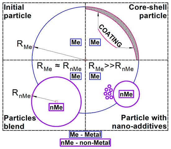
Figure 1. Types of initial powder morphology for SLM of metal-matrix composites with nonmetal additives.
The main features of the initial powder preparation, including the powder morphologies and mixing regimes used in the observed studies, are collected in Table 1.
Table 1. Feedstock powder characterization.
| Material | Powder Morphology | Mixing Regime | Reference |
|---|---|---|---|
| Al-Al2O3 80:20 weight ratio |
Al—1.02 µm average particle size; Al2O3—9.04 µm. |
High-energy planetary mono-mill. 16 h with interval of 10 min after each 30 min of milling. 200 rpm. | [63] |
| AlSi10Mg-Al2O3 80:20 weight ratio |
AlSi10Mg—gas atomized, 30 µm average particle size; Al2O3—9.04 µm. |
Ball-to-powder weight ratio of 10:1, a rotation speed of 200 rpm, and a milling time of 8 h. | [80,81,82] |
| Al and 4 vol.% of Al2O3 | Al—17.1 µm average particle size; Al2O3—10.37 µm. |
Ball-to-powder weight ratio of 5:1, 350 rpm, 20 h. Milling of 15 min and pause of 5 min (method 1), milling of 10 min and pause of 15 min combination (method 2) |
[66,83,84] |
| AlSi10Mg + 2–5wt.% nanoAl2O3 | AlSi10Mg—atomized, 42 µm average particle size; nAl2O3—270 nm |
Single-axis ball milling at 600 rpm, 5 h, ball-to-powder ratio of 1:1 in a volatile solvent | [76] |
| Al2O3-AlSi10Mg 1:1 weight ratio | AlSi10Mg—33.1 µm average particle size; Al2O3—26.6 µm |
Tumbling ball mill, weight ratio of 1:1 | [85] |
| Al2O3- AlSi10Mg 15:85 weight ratio |
AlSi10Mg—33.1 µm average particle size; Al2O3—26.6 µm |
10:1 ball-to-powder weight ratio. 4 h, 70 rpm. |
[86,87] |
| Al + 10 wt.% Al2O3 core–shell | D50 = 42 μm with narrow SPAN (D90 − D10)/D50 = 1.1) | Core–shell Al-Al2O3 powder obtained by hydrothermal oxidation | [78] |
3. SLM Regimes, Process Window, and Microstructure
The primary definition and optimization of the SLM parameters route for any new material is generally the same and represents a narrowing of the processing parameters window. The ED may change through variations in the laser power P or scanning speed v. Laser power has a directly proportional effect on the ED value, whereas the scanning speed has an inverse proportion, i.e., the higher the speed, the lower the energy supplied to the material per unit time. It is also worth noting that a lower temperature of the melting pool implies a poor viscosity of the melt and, hence, a poor wettability of the previous printed layer and Al2O3 particles suspended in the melt. Overall, too high a scanning speed leads to a discontinuous melting process, forming unmelted regions, pores, and cracks. Therefore, the densification rate of the material after such laser melting will not be high enough.
On the contrary, low scanning speeds increase the heated area and melting pool temperature, possibly leading to its boiling and, in turn, intensive evaporation and spattering. This not only results in pore formation but also causes undesirable chemical and phase transformations, the shrinkage of porosities, and the formation of thermal cracks [63]. In addition, this route of optimization of SLM parameters should be performed not only in new material development cases but also for each SLM machine, because of differences in their characteristics and features. Process windows for the synthesis of Al-Al2O3 composites used in various studies are depicted in Figure 2 as ranges of P–V ratios. Rays of the same P–V ratio indicate the same LED; regions between boundary rays of the same colors indicate the ranges of the used LED in the current research. The overall window includes the wide range of P–V ratios in which the tightly overlapped region is clearly seen. An insufficient laser power as a rule leads to the formation of unmolten defects (lack-of-fusion porosity region in Figure 2). Too slow a scanning speed, in turn, leads to keyhole porosity, while too high an ED initiates the balling effect [88,89], as well as boiling and evaporation of the melt (discussed in detail in Section 4). It does not mean that optimal SLM regimes must lie within the process window; on the contrary, an optimal P–V ratio could even go out of the frame of the overall window shown because of other factors such as powder morphology, layer thickness, hatch spacing, and scanning strategy. All boundaries of the mentioned regions are smooth. However, Figure 2 displays the most possible optimal window that one can focus on to start the optimization of the SLM parameters route. It should be mentioned that although such a direct comparison of the SLM regimes as in Figure 2 is not completely correct, because of other parameters and the difference in machine features, all reviewed research of Al-Al2O3 composites was performed using similar continuous-wave ytterbium fiber lasers of various powers with a TEM00 laser operation mode [90].
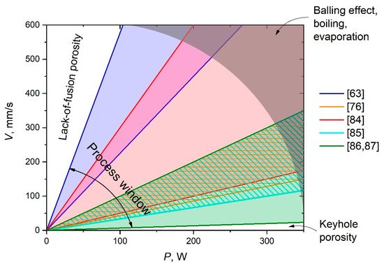
Figure 2. P–V diagrams representing process windows for Al-Al2O3 composites synthesis.
Such a route can be clearly seen in a previous study [63] applied to Al-Al2O3 composites. Densification levels from 80.6% up to 97.3% were obtained depending on the variation in scanning speed. The best result with a high relative density (RD) corresponded to a v of 550 mm/s (LED = 236 J/m), which is reasonable and optimal within the discovered processing window. Lower or higher scanning speeds decrease the densification level significantly. It should be recalled that a high volume of unmelted Al2O3 regions on the depicted microstructures and a reduced densification level could be partly explained by the feedstock powder morphology features mentioned above. It is worth noting that a simple linear scan pattern was employed in this study, whereas many recent studies [91,92,93,94] showed complex strategies (such as a 67° rotation between layers and chessboard) to be more effective at obtaining a high density and porous-free material.
In a study by Han et al. [83], a Renishaw AM250 SLM machine was employed to print 8 × 8 × 8 mm3 cubic samples, and a striped fill-hatch-type scanning strategy was performed with the 67° rotation between each layer. A laser power of 200 W and a scanning speed of 300 mm/s (EDV = 317.5 J/mm3) were found as optimum SLM parameters to synthesize the material with a high density of 99.49% [84]. Du et al. [76] reported the SLM of the AlSi10Mg and nAl2O3 composite on the SLM 250HL machine with an 80 µm laser spot size, a layer thickness of 0.05 mm, a laser power of 350 W, a scanning speed range of 100–1500 mm/s, and a 0.1–0.2 mm hatch spacing, providing an EDV varying from 35 to 150 J/mm3. The chessboard island strategy with a 67° rotation was employed. The authors found that the use of a higher EDV (109–175 J/mm3) is appropriate for dense samples of the AlSi10Mg-nAl2O3 composite, explaining it by the insulation of AlSi10Mg particles via the nAl2O3 layer. In addition, an increase in composite melting pool viscosity was observed, leading to porosity defects due to the weak inter-line bonding or discontinuous melting process.
Balling phenomena [89], leading to poor interline bonding and gaps at low EDV, were observed. A higher EDV induced the porosity formation that Du et al. [76] attributed to the increased recoil pressure. Moreover, it resulted in a higher unstable melt flow and melt splashing induced by both the Marangoni convection and the recoil pressure, along with the vapor intensification [95].
Besides this, Du et al. was faced with the dynamic keyhole process, leading to pore formation during rapid solidification, inherent in the aluminum alloy with elements of low boiling points such as Si, Mn, and Mg [96]. The decrease in RD was determined not only by porosity but also by crack formation. Du et al. observed thermal shrinkage and cracks in solidified alumina along with small cavities at the edge of the nAl2O3 after the low EDV SLM process. According to [63,84], an increase in EDV improves the particle–matrix interface.
The SLM of the Al-Al2O3 core–shell composite with 10 wt.% of alumina prepared by the special technique described in [77] was performed by authors of a previous study [78]. The EDa of 7–8 J/mm2 was found to be the optimal range for the SLM of Al-10 wt.% Al2O3 core–shell powder composites, whereas the lower and higher energies caused an incomplete melting and aluminum boiling, respectively. Moreover, a lower ED insufficient for Al2O3 melting led to the agglomeration at molten pool boundaries and weak bonding between the matrix and reinforcement due to the γ-Al2O3 to α-Al2O3 phase transition. On the contrary, the EDa increased beyond the 8 J/mm2 activated deoxidation and boiling of the molten pool processes. Both incomplete melting and boiling reduced the density. The employment of EDa = 7.69 J/mm2 with P = 220 W, h = 0.13, and V = 220 mm/s led to the highest sample hardness (58.3 ± 0.9 HB) and RD (96.5%). Such a relatively low RD was explained by the authors by the γ- to α-Al2O3 phase transition and the particle aggregations. Further research into the double-layer exposure of the SLM mode is needed to overcome these problems. The already used and studied SLM regimes in detail are presented in Table 2.
Table 2. SLM parameters and RD.
| Material | SLM Parameters | Maximum RD, % | Reference |
|---|---|---|---|
| Al-Al2O3 80:20 weight ratio | Spot size = 70 µm, linear raster scan pattern, P = 130 W, V = 450, 550, 650, 750 mm/s, LED = 173, 200, 236, 289 J/m |
97.3 | [63] |
| Al and 4 vol.% of Al2O3 | Renishaw AM250, preheated T = 170 °C, P = 200 W, V = 100–600 mm/s (300 is optimal), t = 30 µm h = 70, 100 μm. |
99.49 | [84] |
| AlSi10Mg + 2–5wt.% nano-Al2O3 | SLM 250, chessboard island strategy with a rotation of 67° at every layer. P = 350 W, V = 100–1500 mm/s, h = 0.1–0.2 mm. EDV = 35–150 J/mm3 (109 is optimal) |
– | [76] |
| Al2O3-AlSi10Mg 1:1 weight ratio | SLM-100, P = 200 W, V = 150, 200, 250, 300, and 350 mm/s(250–350 are optimal), t = 20 µm, h = 0.05, 0.1 µm (0.1 is optimal) |
93 | [85] |
| Al2O3-AlSi10Mg 15:85 weight ratio |
P = 200 W, V = 100–300 mm/s, t = 20 μm, h = 60–160 μm |
– | [86,87] |
| Al + 10 wt.% Al2O3 core–shell | SLM 280 HL, P = 220 W, V = 220 mm/s, EDa = 7–8 J/mm2, h = 0.13 |
96.5 | [78] |
The casting technology proposed in [33] allowed a porosity of 1.18% to be obtained for the composite with 1% of Al2O3. The porosity increased with Al2O3 content and reached more than 6% for a maximum alumina concentration of 10%. With such a complex route as stir casting with heat treatment, the addition of heat-treated particles to the melt by an inert argon gas flow could not provide a low porosity of at least less than 1%. In a previous study [41], relatively high values of RD (about 0.97) were reached only for 1 vol.% of nano-alumina after at least 150 min of sintering. The increase in both the volume fraction and particle size of alumina drastically decreased the RD. This showed the great complexity of melting and sintering approaches to produce fully dense Al-based matrix composites with Al2O3 reinforcement, wherein RD < 0.99 is usually considered unsatisfactory in the SLM case. The main results of the relative densities of SLMed AMCs with Al2O3 achieved in various studies are shown in Figure 3.
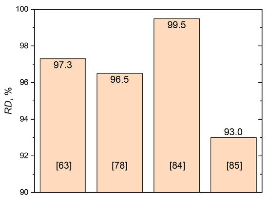
Figure 3. Maximum RD values of AMC + alumina materials achieved by means of the SLM technique.
It should be mentioned that there is another indirect way to obtain the Al-Al2O3 composite described in [97,98]. The initial mixture of Al and 5 wt.% Fe2O3 was SLMed at a laser power of 40–90 W and a scanning speed of 70–140 mm/s. The heating of the material during the melting initiated the following reaction:
8Al + 3Fe2O3 → 2Fe3Al + 3Al2O3 + heat
Eruptive sparks were observed during the process because of the extra heat that contributed to powder melting and molten pool extension. The fine particles with a uniform distribution in the Al matrix were defined as alumina and phases of Al, Fe, and O acting as reinforcements.
Thus, it was shown that the SLM process allows the synthesis of the particles-reinforced AMC by in situ reaction. Unfortunately, there is no information about RD or any mechanical properties in that study, so it is impossible to compare the produced material with analogs.
4. Melting Pool Behavior
Processes within the melting pool during selective laser melting run extremely fast; hence, it is of great difficulty to study them. Some conclusions could be formulated based on the microstructural features after solidification. Jue et al. [63] showed the formation of agglomerated regions or a long-strip or ring morphology of Al2O3 particles because of their displacement to the boundaries of the melting pool. The exact character of such a structure depended on the energy density of the SLM, but generally, it showed a far-from-desirable microstructure with a nonuniform distribution of reinforcing particles in the composite, which prevented the achievement of high mechanical properties (discussed in the next section). Jue et al. [63] claimed that the complete melting of the initial powder occurs, including the Al2O3 phase and its formation during melting runs through the dissolution/precipitation mechanism. However, there are reasons [99,100] to believe that lower energy densities within the process window of Al-based materials via SLM do not correspond to temperatures above ~1600–1800 °C, which is lower than the alumina melting point (2044 °C); hence, the complete melting of the Al2O3 phase during SLM could be achieved only at elevated energy density levels. High EDs sufficient for the melting of Al2O3 could also be accompanied by undesirable processes of aluminum melt boiling (Al boiling temperature is 2519 °C), and its evaporation and emission. There are a series of studies about alumina loss during the Al-Al2O3 SLM process [86,87] that shows a temperature of the melting pool higher than the alumina melting point at any set of investigated SLM parameters. If the temperature of the molten pool is strongly influenced by the process parameters, the Al2O3 loss phenomenon may also be controlled by the SLM regime: the setting temperature of the molten pool above the Al2O3 melting point leads to alumina melt and resolidification; setting it above the boiling point (2977 °C) leads to alumina vaporization and loss [86]. The boiling point of Al is 2519 °C, so in the case of the temperature of the molten pool being higher than the alumina boiling point, Al will intensely burn. Thus, the presence or absence of Al loss during melting may be a marker of the molten pool temperature. In fact, no Al loss was usually observed, which means a temperature of the molten pool below 2500 °C, thus being far from the alumina boiling point. Liao et al. concluded that a notable Al2O3 loss could not be explained by vaporization. According to Laurent et al. [62], deoxidization by the dissociative vaporization of alumina becomes noticeable only at temperatures much higher than the melting point of aluminum. Some disruption of the alumina surface could be possible in the vicinity of the Al melting point; however, it only affects a film of a few monolayers in thickness. Besides the laser power and scanning speed, hatch spacing also affects the Al2O3 loss—the higher the hatch spacing, the lower the Al2O3 loss. However, this dependence was observed to be nonlinear [86]—the Al2O3 loss at a hatch spacing of 0.06 mm was smaller than that at a hatch spacing of 0.08 mm. It was explained by the difference in the laser absorptivity of the solid and powder [101], thus decreasing the temperature of the molten pool at higher overlap. According to [87], the main loss mechanism of Al2O3 is the reduction in the reaction of Al2O3 by aluminum. A critical temperature of 1520 °C was in the case of the Al2O3-AlSi10Mg composite, so it was lower than the usually observed molten pool temperature under laser irradiation. Thus, notable Al2O3 burning loss can be expected during the SLM and should be taken into account.
Returning to the temperature of the molten pool, there are some studies about the SLM/SLS of the Al2O3 ceramic [102,103] that showed the LED values normalized to the square of the laser spot to be of the same order as those for Al-based materials melting, making the consideration about the state of alumina particles within the melting pool highly controversial. At the same time, it should be noted that, first, any discussion about reinforcing the particle distribution within the melting pool involves the presence of those particles in the solid state and, secondly, extremely high heating and cooling rates with a short lifetime of the melting pool somewhat obstruct the complete melting of Al2O3. Therefore, it is possible to make an assumption that the behavior of Al2O3 particles in the melting pool may be considered as suspended solids within liquid. Based on this, the wettability of alumina by molten aluminum should be clarified. Laurent et al. [62] studied the problem and found that the contact angle θ smoothly decreased within the range from 933 (θ = 103 ± 6°) to 1273 K (θ = 86 ± 6°), which means that the higher the temperature of the melting pool, the better the wettability.
The segregation of Al2O3 particles during solidification is another phenomenon that should be discussed. This phenomenon arises because the Al2O3/solid-Al interfacial energy is higher than the Al2O3/liquid-Al energy [104,105], and the difference acts as a driving force, pushing alumina particles into the melt [106,107,108]. The so-called “particle pushing” results in the redistribution or segregation of the Al2O3 particles into regions that are last to solidify.
Extremely high cooling rates inherent in SLM allow this phenomenon to be successfully avoided and allow a uniform distribution of reinforced particles to be obtained, as it was accomplished on the powder mixing/milling stage. Jue et al. [63,80] also considered the distribution of alumina in the Al matrix specifically for SLM, taking into account the Marangoni convection and induced liquid capillary forces that accelerate the particle rearrangement, making it possible to obtain a homogeneous structure after SLM. Han et al. [84] studied the melting pool temperature during SLM with a 200 W laser power. It was observed that melting at a low scanning speed of 200 mm/s could provide the heating of the melt above the alumina melting point (2040 °C). Du et al. [76] claimed that even a higher energy input and the melting of at least some part of the nAl2O3 could result in the increase in the nAl2O3 particle size. In the studies of both Du et al. and Han et al., Al2O3 particle agglomerations were observed along the melt track edges (see Figure 4), which was explained by reinforcing particles pushing outward due to Marangoni convection and the recoil pressure.
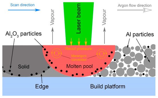
Figure 4. Schematic representation of reinforcing particles distribution and agglomeration along the melt track edges.
This entry is adapted from the peer-reviewed paper 10.3390/ma14102648
This entry is offline, you can click here to edit this entry!