An opto-electronic oscillator (OEO) is one of the most popular types of oscillators for generating micro- and millimeter wave signals.
- opto-electronic oscillator
- phase noise
- microwave signal
- millimeter wave signal
1. Introduction
High-precision signal oscillators are needed in a variety of fields such as satellite communications, optical communications, radar applications, radio-over-fiber communications, etc. [1]. In its most basic form, an oscillator consists of a resonator and a feedback component. When the Barkhausen conditions are satisfied, the oscillator starts generating the fundamental oscillation signal. An opto-electronic oscillator (OEO) is one of the most popular types of oscillators for generating micro- and millimeter wave signals [2][3]. The OEO has a number of optical components such as a laser diode [4][5], an optical fiber [6] and a photodiode [7]. The electrical components including an electrical bandpass filter and an electrical amplifier are used to complete the feedback loop. The laser of the OEO can be modulated directly, or it can use external modulation with an electro-optic modulator such as a Mach Zehnder modulator (MZM) [8] or an electro-absorption modulator [9]. A typical externally modulated OEO is shown in Figure 1.

Figure 1. Single-loop opto-electronic oscillator (OEO) with electrical components.
Currently, −163 dBc/Hz at a 6 kHz offset from the carrier for an operating frequency of 10 GHz [10] is the lowest phase noise achieved so far. Different types of configurations for the OEO have already been presented in the literature. The dual-loop and multi-loop configurations [11][12][13][14], coupled OEO [15][16][17][18], injection-locked OEO [19][20][21][22], OEO with quality multiplier [23], and OEO with feedback loop [24] are some of the well-known configurations. Moreover, optical solutions are possible by adding components such as optical filters [25][26][27] and optical amplifiers [28][29] or by adjusting the optical link to achieve an optical gain [30]. These are already used to improve the stabilization of the OEO. Since an OEO consisting of such bulky components is very large, some methods to reduce the size of the oscillator device have already been reported. There are several solutions such as using a whispering-gallery-mode resonator (WGMR) [31][32][33][34], a ring resonator [35][36], or an electro-absorption modulated laser [37] that decrease the size of the OEO. In 2017, a fully integrated OEO was reported in the literature by J. Tang et al. [38][39]. In addition, a theoretical and experimental study of the characteristics of an injection-locked OEO was presented and published in several journals [40][41][42][43][44]. Recently, a W-band OEO was introduced by G.K.M. Hasanuzzaman et al. [45]. The OEO provided a phase noise characteristic of −101 dBc/Hz at a 10 kHz offset from the 94.5 GHz carrier. On the other hand, an opto-electronic parametric oscillator [46] was reported in 2020.
There are some more recent developments in the use of OEOs in various applications. One example of this is terahertz (THz) photonic signal generation using an OEO [47][48][49]. Another possible application of an OEO is to use it as a local oscillator (LO) in the central office of a 5G radio access network (RAN) [50][51][52]. The single-loop OEO can be combined with an optical fiber path selector to measure the free spectral range (FSR) and side-mode suppression ratio (SMSR) of the OEO for different lengths of the optical delay line [53]. There are other applications of OEOs such as an acoustic sensor [54], low-power radio frequency (RF) signal detection [55], phase-locked loops [56][57][58], parity time-symmetric OEO [59][60], silicon micro-ring-based OEO [61] and linear frequency-modulated waveform generation [62], etc.
Long-term stability and side modes (multimode operation) are the main challenges affecting the stabilization of an OEO. The OEO uses an optical fiber that is mainly affected by the temperature variations in the environment. This leads to fluctuations in the oscillation frequency over time, which is referred to as the frequency drift (in other words, long-term stability). On the other hand, electrical bandpass filters have bandwidth limitations in the micro- and millimeter wave ranges. Electric bandpass filters are used in the oscillator loop to destroy the side modes in the RF spectrum and determine the main mode of the oscillation. Due to the bandwidth limitation of the filter, the side modes are not completely filtered out, and they can therefore be seen in the RF spectrum. The ratio between the fundamental mode and the spurious side modes is called SMSR.
The short-term stability (i.e., phase noise) is mainly based on the length of the delay line of the OEO. The OEO can use a long delay line to achieve the lowest possible phase noise. However, using a long delay line boosts the power of the side modes because the FSR becomes lower, and the side modes are more difficult to filter out due to the bandwidth limitation of the electrical filter. For instance, the use of a 1-km fiber has an FSR of 200 kHz, while a 15 km fiber has an FSR of 13.4 kHz. The relationship between SMSR and phase noise performance of the OEO at different optical lengths is shown in Figure 2.
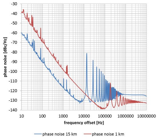
Figure 2. Comparison of phase noise and side-mode suppression ratio (SMSR) performance of OEO with 1 km and 15 km delay line length [1]. Reprinted with permission from ref. [1]. Copyright 2015 IEEE.
As can be seen from the experimental results in Figure 2, there is a tradeoff between the short-term stability and multimode operation of the OEO. The 1 km OEO has about a 30 dB improvement performance in the SMSR, but the 15 km OEO has a significant improvement in phase noise, which is about 20 dB at 1 kHz and 10 kHz offsets from the carrier.
2. Current Progress of the Common Topologies of the OEO
In this section, the paper focuses on recent advances in the development of OEOs and the main challenges that they face: multimode operation, as well as short-term and long-term stability. In the first subsection, the paper focuses on multimode operation and short-term stability, with long-term stability following this subsection.
2.1. Progress of the OEO toward Lower SMSR and Phase Noise
As mentioned earlier, one of the general challenges associated with OEO design is multimode operation. Since an electrical bandpass filter has bandwidth limitations, some optical solutions have been proposed. One of the most popular solutions is to form more than one optical delay line. These dual or multi-loop OEOs have seen widespread use for more than 20 years to eliminate multimode operation [63]. The typical configuration of a dual-loop OEO is shown in Figure 3. In this configuration, one loop is used as a long cavity, while the other behaves as a short cavity. This is achieved by using short and long fibers in different loops. One of the recent advances in the dual-loop OEO is the use of multicore fibers and the self-polarization-stabilization technique [64]. Conventionally, two or more single-mode fibers (SMFs) are used to form a dual- or multi-loop configuration. In this novel approach, the combination of cores in a multicore fiber is used to form a short and a long cavity [64]. With this novel approach, an SMSR of 61 dB was achieved for a microwave OEO oscillating at 7.8 GHz. Another recent approach is parity symmetry of the OEO with a dual-loop configuration [65]. The parity symmetry is achieved by using two optical carriers with different optical powers. Parity symmetry provides additional gain for the main mode. With the combination of parity symmetry and a dual loop, a 60.71 dB SMSR was achieved for a 10 GHz central frequency.
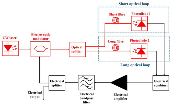
Figure 3. Typical dual-loop configuration of an OEO.
An injection-locked OEO is another configuration to improve the SMSR performance of the OEO. It was first proposed in 2005 [63][66]. The typical configuration of an injection-locked OEO is shown in Figure 4. In the typical configuration of the OEO, it consists of two oscillator blocks. One of them is classified as the master OEO and other as the slave OEO [63]. This approach is used to suppress the spurious side modes and at the same time maintain the quality factor (Q-factor) of the OEO [63]. The slave OEO is used to suppress the spurious side modes as it employs a short fiber, while the master OEO employs a long fiber to keep the high Q-factor. In reference [67], a tunable, dual-loop, injection-locked OEO was presented. The OEO was tunable from 11.1 GHz to 12.1 GHz, and the spurious side modes were suppressed below −115 dBc/Hz [67]. Another approach was to form a microwave frequency divider based on the injection-locked OEO [68]. In this implementation, the 10 GHz free-running OEO was injected with a 20 GHz microwave signal. A single-sideband (SSB) phase noise of −130 dBc/Hz at a 10 kHz offset was achieved. In Reference [69], an injection-locked OEO based on stimulated Brillouin scattering (SBS) is described. This approach provided a frequency tunability up to 40 GHz with an SMSR of 60 dB and an SSB noise of −116 dBc/Hz at a 10 Hz offset.
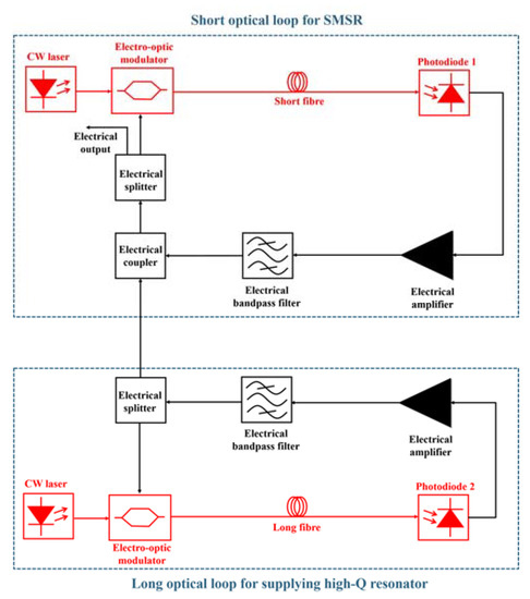
Figure 4. Typical injection-locked OEO.
The coupled OEO, introduced in 1997 [63][70], is another type of commonly used OEO configuration to improve SMSR. In this configuration, the OEO consists of an optical loop and an opto-electronic loop coupled via an electro-optic modulator [63]. The coupled OEO is used to improve the phase noise characteristics and the SMSR. The typical configuration of a coupled OEO is shown in Figure 5. An example of a recent development in the coupled OEO was the synthesis of a 90 GHz signal using a 30 GHz coupled OEO [71]. The 90 GHz signal was obtained by biasing the MZM to the third harmonic. An SSB phase noise of −104 dBc/Hz at a 1 kHz offset from the 90 GHz carrier was achieved in this configuration [71]. On the other hand, a novel, coupled OEO with an erbium-doped fiber (EDF) has been proposed [72]. The novel configuration allows a large spatial hole burning (SHB) using the unpumped EDF to improve the SMSR and the phase noise. An SMSR of more than 72.5 dB was achieved wherein the SSB phase noise was −123.6 dBc/Hz at a 10 kHz offset from the 10 GHz carrier signal.
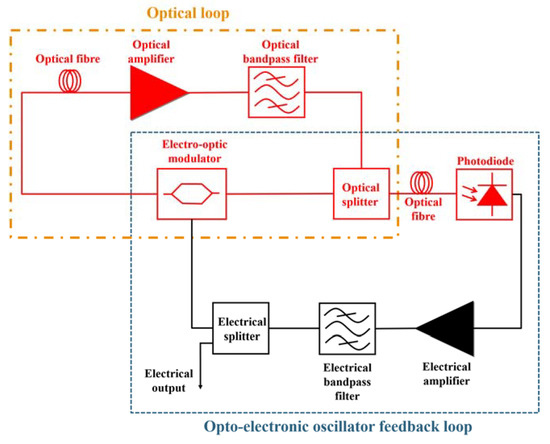
Figure 5. Typical configuration of a coupled OEO.
In addition to the typical solutions listed above, there are other novel solutions to improve the phase noise and/or the SMSR characteristics of the OEO. For a millimeter-wave OEO, a high-quality opto-electronic filter was proposed, e.g., a Q-factor of 30,000 at a central frequency of 29.99 GHz [73]. This resulted in an 83 dB SMSR and a −113 dBc/Hz SSB phase noise at a 10 kHz offset. A cascaded microwave filter was presented in [49]. In this configuration, the cascaded filter configuration was implemented with a single passband filter having an opto-electronic filter. With this approach, an SMSR of 125 dB and an SSB phase noise of −103 dBc/Hz for a 10 kHz offset at the 17.33 GHz carrier were achieved. The linewidth of the laser can affect the phase-noise performance of the OEO. A narrowband microcavity laser with a physical side length of 16 μm is used for the microwave signal generation in the loop of the OEO [74]. An SSB phase noise of −116 dBc/Hz was achieved for a 10 kHz offset from the carrier microwave signal. The microwave signal can be tuned between 1.85 GHz and 10.24 GHz thanks to a tunable optical bandpass filter.
2.2. Progress of the OEO toward Better Long-Term Stability
Long-term stability is another important characteristic of the OEO. The electrical bandpass filter and the optical fiber are major components of the OEO that are temperature-dependent [75]. For the frequency drift of a non-temperature-stabilized OEO operating at a 10 GHz central frequency, 8 ppm/K was measured [75]. One of the useful approaches is the temperature stabilization of the optical fiber and the electrical bandpass filter of the OEO loop [75]. With this solution, 0.1 ppm/K was achieved. In 2016, Luka Bogataj et al. brought another approach, i.e., the OEO with a feedback control loop [24][76]. The configuration of the feedback control loop is shown in Figure 6.
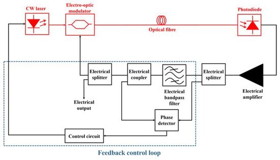
Figure 6. OEO with a feedback-control loop.
In the feedback control loop, the frequency discriminator controls the temperature of the laser by measuring the refractive index of the optical fiber. A proportional–integral (PI) controller is used to control the temperature of the laser. Using the feedback control loop, a frequency drift of 0.05 ppm/K was achieved for a single-loop OEO operating at 3 GHz. In 2017, the optical delay stabilization system (ODSS) was introduced [77] for active fiber delay stabilization at a different wavelength than used in the oscillator loop. The outstanding result of a 0.02 ppm/K frequency drift was achieved for a 3 GHz OEO. However, the frequency of the oscillator can be increased, but this does not affect the stability result because the stabilization is performed at an independent wavelength.
Phase-locked loops (PLLs) are alternative solutions that are widely used in practice to improve the long-term stability of the OEO signal. In this case, the OEO signal is locked by the PLL signal [78]. The typical configuration of an OEO with a PLL is shown in Figure 7.
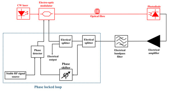
Figure 7. Typical configuration of an OEO with a PLL configuration.
For an OEO with a PLL configuration, a stable reference signal is required to improve the long-term stability. Wen-Hung Tseng proposed another approach to improving the long-term stability that involves a fiber-delay monitoring mechanism [79]. This mechanism monitors the fiber delay using an injected probe signal. A thermal drift of 10−7 s was achieved after 4000 seconds with the monitoring mechanism.
2.3. General Overview
In this section of the paper, we would like to compare the performance of different configurations of the OEO in multimode operation: short-term stability (i.e., phase noise) and long-term stability. In the first table, different configurations of the OEO are described by comparing the SMSR and the phase noise.
For Table 1, OEOs with the same or similar frequency were selected (except for the OEO with a high quality opto-electronic filter) to allow a more accurate and scientific comparison of the phase noise in different solutions. However, in theory, the OEO has a stable phase-noise characteristic that is independent of the operating frequency [1], so higher frequencies can be used for the comparison. In the SMSR comparison, the optical delay line length and the bandwidth of the electrical and/or optical filter are more important for the comparison. When considering the phase noise, the injection-locked OEO achieves the best performance among the other solutions. On the other hand, the cascaded micro-wave photonic filter solution achieved a better result in terms of the SMSR.
Table 1. Comparison of the SMSR and the phase noise of the current results for various advanced configurations of the OEO.
| Configuration | Optical Delay Line Length | Central Frequency | SMSR | Phase Noise (@10 kHz offset from the carrier) |
|---|---|---|---|---|
| Dual-loop OEO [64] | 7-core fiber (105 m) |
From 3.5 GHz to 17.1 GHz | 61 dB | −100 dBc/Hz |
| Injection-locked OEO [68] | Single-mode fibers (1 km and 0.7 km) |
10 GHz | N/A | −130 dBc/Hz |
| Coupled OEO [72] | Erbium-doped fiber (4 m) |
10 GHz | 72.5 dB | −123.6 dBc/Hz |
| OEO with high-quality opto-electronic filter [73] | Dispersion-shifted fiber (3 km) | 29.99 GHz | 83 dB | −113 dBc/Hz |
| Cascading microwave photonic filter [49] | Single-mode fibers (2 km and 0.2 km) |
17.33 GHz | 125 dB | −103 dBc/Hz |
| Narrowband microwave laser with dual-loop OEO [74] | Single-mode fibers (2.5 km and 3 km) |
From 1.85 GHz to 10.24 GHz | 55 dB | −116 dBc/Hz |
In Table 2, different solutions are compared to evaluate the performance of the OEO in terms of long-term stability and phase noise.
Table 2. Comparison of the different techniques to achieve long-term stability in the OEO.
| Configuration | Optical Delay Line Length | Central Frequency | Long-term Stability | Phase Noise (@10 kHz offset from the carrier) |
|---|---|---|---|---|
| Temperature stabilization [75] | N/A | 10 GHz | 0.1 ppm/K | −143 dBc/Hz |
| OEO with feedback-control loop [76] | 15 km | 3 GHz | 0.05 ppm/K | < −130 dBc/Hz |
| Optical delay stabilization system [77] | 3 km | 3 GHz | 0.02 ppm/K | −123 dBc/Hz |
| OEO with PLL [78] | 500 m (Dispersion deduced fiber) |
3 GHz | 6.98 × 10⁻¹⁴ (average time of 1000 s) |
< −100 dBc/Hz |
The optical delay line system showed good performance in terms of long-term and short-term stability. The phase-noise performance could be improved by using a longer optical fiber. An OEO with a PLL does not have good phase noise performance because a short delay line is used. However, a classic solution such as temperature stabilization has good phase noise performance and short-term stability.
This entry is adapted from the peer-reviewed paper 10.3390/electronics10070857
References
- Batagelj, B.; Bogataj, L.; Vidmar, M.; Bostjan, B. Key properties and design issues for an opto-electronic oscillator. In Proceedings of the 2015 17th International Conference on Transparent Optical Networks (ICTON), Budapest, Hungary, 5–9 July 2015; Institute of Electrical and Electronics Engineers (IEEE): New York, NY, USA, 2015; pp. 1–4.
- Liu, A.; Dai, J.; Xu, K. Stable and Low-Spurs Optoelectronic Oscillators: A Review. Appl. Sci. 2018, 8, 2623.
- Yao, X.; Maleki, L. Opto-electronic oscillator and its applications. In International Topical Meeting on Microwave Photonics; MWP 2000 (Cat. No.00EX430); Institute of Electrical and Electronics Engineers (IEEE): New York, NY, USA, 2002; pp. 265–268.
- Tang, J.; Zhu, B.; Zhang, W.; Li, M.; Pan, S.; Yao, J. Hybrid Fourier-domain mode-locked laser for ultra-wideband linearly chirped microwave waveform generation. Nat. Commun. 2020, 11, 1–8.
- Sun, Y.; Zhou, K.; Feng, M.; Li, Z.; Zhou, Y.; Sun, Q.; Liu, J.; Zhang, L.; Li, D.; Sun, X.; et al. Room-temperature continuous-wave electrically pumped InGaN/GaN quantum well blue laser diode directly grown on Si. Light. Sci. Appl. 2018, 7, 13.
- Corcoran, B.; Tan, M.; Xu, X.; Boes, A.; Wu, J.; Nguyen, T.G.; Chu, S.T.; Little, B.E.; Morandotti, R.; Mitchell, A.; et al. Ultra-dense optical data transmission over standard fibre with a single chip source. Nat. Commun. 2020, 11, 1–7.
- Wang, B.; Morgan, J.S.; Sun, K.; Jahanbozorgi, M.; Yang, Z.; Woodson, M.; Estrella, S.; Beling, A.; Yi, X. Towards high-power, high-coherence, integrated photonic mmWave platform with microcavity solitons. Light. Sci. Appl. 2021, 10, 1–10.
- Wang, L.; Zhu, N.; Li, W.; Liu, J. A Frequency-Doubling Optoelectronic Oscillator Based on a Dual-Parallel Mach–Zehnder Modulator and a Chirped Fiber Bragg Grating. IEEE Photon. Technol. Lett. 2011, 23, 1688–1690.
- Liu, M.; Yin, X.; Ulin-Avila, E.; Geng, B.; Zentgraf, T.; Ju, L.; Wang, F.; Zhang, X. A graphene-based broadband optical modulator. Nat. Cell Biol. 2011, 474, 64–67.
- Eliyahu, D.; Seidel, D.; Maleki, L. Phase noise of a high performance OEO and an ultra low noise floor cross-correlation microwave photonic homodyne system. In Proceedings of the 2008 IEEE International Frequency Control Symposium, Honolulu, HI, USA, 18–21 May 2008; IEEE: New York, NY, USA, 2008; pp. 811–814.
- Levy, E.; Horowitz, M.; Okusaga, O.; Menyuk, C.; Carter, G.; Zhou, W. Study of dual-loop optoelectronic oscillators. In Proceedings of the 2009 IEEE International Frequency Control Symposium Joint with the 22nd European Frequency and Time forum, Besancon, France, 20–24 April 2009; IEEE: New York, NY, USA, 2009; pp. 505–507.
- Banky, T.; Horvath, B.; Berceli, T. Optimum configuration of multiloop optoelectronic oscillators. J. Optical Soc. of Am. B. 2006, 23, 1371–1380.
- Shumakher, E.; Eisenstein, G. A Novel Multiloop Optoelectronic Oscillator. IEEE Photon. Technol. Lett. 2008, 20, 1881–1883.
- Wang, W.; Liu, Y.; Du, X.; Yan, Y.; Yu, C.; Chen, X. A Novel Demodulation Method of Fiber Bragg Grating Sensor Array Based on Wavelength-to-time Mapping and Multiloop Optoelectronic Oscillator. In Optical Fiber Communication Conference (OFC) 2020; The Optical Society: Washington, DC, USA, 2020.
- Zhu, D.; Du, T.; Pan, S. A Coupled Optoelectronic Oscillator with Performance Improved by Enhanced Spatial Hole Burning in an Erbium-Doped Fiber. J. Lightw. Technol. 2018, 36, 3726–3732.
- Yao, X.; Davis, L.; Maleki, L. Coupled optoelectronic oscillators for generating both RF signal and optical pulses. J. Lightw. Technol. 2000, 18, 73–78.
- Khayatzadeh, R.; Auroux, V.; Bailly, G.; Fernandez, A.; Llopis, O. Phase noise study based on transfer function in coupled optoelectronic oscillators. In Proceedings of the 2017 International Topical Meeting on Microwave Photonics (MWP), Beijing, China, 23–26 October 2017; Institute of Electrical and Electronics Engineers (IEEE): New York, NY, USA, 2017; pp. 1–4.
- Lelievre, O.; Crozatier, V.; Baili, G.; Nouchi, P.; Dolfi, D.; Morvan, L.; Goldfarb, F.; Bretenaker, F.; Llopis, O. Low phase noise 10 GHz coupled optoelectronic oscillator. In Proceedings of the 2017 Joint Conference of the European Frequency and Time Forum and IEEE International Frequency Control Symposium (EFTF/IFCS), Besancon, France, 9–13 July 2017; Institute of Electrical and Electronics Engineers (IEEE): New York, NY, USA, 2017; pp. 493–494.
- Peng, H.; Du, H.; Guo, R.; Xu, Y.; Zhang, C.; Chen, J.; Chen, Z. Highly Stable and Low Phase Noise 10 GHz RF Signal Generation Based on a Sub-Harmonic Injection Locked Optoelectronic Oscillator. In Proceedings of the 2018 IEEE International Frequency Control Symposium (IFCS), Olympic Valley, CA, USA, 21–24 May 2018; Institute of Electrical and Electronics Engineers (IEEE): New York, NY, USA, 2018; pp. 1–3.
- Lee, K.; Kim, J.; Choi, W. Injection-Locked Hybrid Optoelectronic Oscillators for Single-Mode Oscillation. IEEE Photon. Technol. Lett. 2008, 20, 1645–1647.
- Hudek, K.; Hati, A.; Howe, D.; Nelson, C.; Zhou, W. Further Examination of the Injection-Locked Dual Optoelectronic Oscillator. In Proceedings of the 2007 IEEE International Frequency Control Symposium Joint with the 21st European Frequency and Time Forum, Geneva, Switzerland, 29 May–1 June 2007; Institute of Electrical and Electronics Engineers (IEEE): New York, NY, USA, 2007; pp. 796–800.
- Lee, K.-H.; Kim, J.-Y.; Choi, W.-Y.; Kamitsuna, H.; Ida, M.; Kurishima, K. Low-Cost Optoelectronic Self-Injection-Locked Oscillators. IEEE Photon. Technol. Lett. 2008, 20, 1151–1153.
- Bogataj, L.; Vidmar, M.; Batagelj, B. Opto-Electronic Oscillator with Quality Multiplier. IEEE Trans. Microw. Theory Tech. 2016, 64, 1–6.
- Bogataj, L.; Vidmar, M.; Batagelj, B. A Feedback Control Loop for Frequency Stabilization in an Opto-Electronic Oscillator. J. Lightw. Technol. 2014, 32, 3690–3694.
- Bagnell, M.; Delfyett, P.J. Optoelectronic oscillator using an ultra-high finesse Fabry-Perot etalon as a photonic filter for low phase noise at high oscillating frequencies. 2013 IEEE Int. Top. Meet. Microw. Photonics 2013, 56–59.
- Ozdur, I.; Mandridis, D.; Hoghooghi, N.; Delfyett, P.J. Low Noise Optically Tunable Opto-Electronic Oscillator with Fabry–Perot Etalon. J. Lightw. Technol. 2010, 28, 3100–3106.
- Ozdur, I.; Mandridis, D.; Hoghooghi, N.; Delfyett, P.J. Tunable opto-electronic oscillator with an intracavity Fabry-Perot etalon. In Proceedings of the 2010 23rd Annual Meeting of the IEEE Photonics Society, Denver, CO, USA, 20–11 November 2010; IEEE: New York, NY, USA, 2010.
- Zhou, W.; Okusaga, O.; Nelson, C.; Howe, D.; Carter, G.M. 10 GHz dual loop opto-electronic oscillator without RF-amplifiers. Integr. Optoelectron. Devices 2008 2008, 6897, 68970Z.
- Huang, N.; Li, M.; Deng, Y.; Zhu, N.H. Optical Pulse Generation Based on an Optoelectronic Oscillator with Cascaded Nonlinear Semiconductor Optical Amplifiers. IEEE Photon. J. 2014, 6, 1–8.
- Nelson, C.; Hati, A.; Howe, D.; Zhou, W. Microwave Optoelectronic Oscillator with Optical Gain. In Proceedings of the 2007 IEEE International Frequency Control Symposium Joint with the 21st European Frequency and Time Forum, Geneva, Switzerland, 29 May–1 June 2007; Institute of Electrical and Electronics Engineers (IEEE): New York, NY, USA, 2007; pp. 1014–1019.
- Nguimdo, R.M.; Saleh, K.P.; Coillet, A.; Lin, G.; Martinenghi, R.; Chembo, Y.K. Phase Noise Performance of Optoelectronic Oscillators Based on Whispering-Gallery Mode Resonators. IEEE J. Quantum Electron. 2015, 51, 1–8.
- Volyanskiy, K.; Salzenstein, P.; Tavernier, H.; Pogurmirskiy, M.; Chembo, Y.K.; Larger, L. Compact optoelectronic microwave oscillators using ultra-high Q whispering gallery mode disk-resonators and phase modulation. Opt. Express 2010, 18, 22358–22363.
- Savchenkov, A.A.; Ilchenko, V.S.; Byrd, J.; Liang, W.; Eliyahu, D.; Matsko, A.B.; Seidel, D.; Maleki, L. Whispering-gallery mode based opto-electronic oscillators. In Proceedings of the 2010 IEEE International Frequency Control Symposium, Newport Beach, CA, USA, 1–4 June 2010; IEEE: New York, NY, USA, 2010; pp. 554–557.
- Merrer, P.-H.; Saleh, K.; Llopis, O.; Berneschi, S.; Cosi, F.; Conti, G.N. Characterization technique of optical whispering gallery mode resonators in the microwave frequency domain for optoelectronic oscillators. Appl. Opt. 2012, 51, 4742–4748.
- Saleh, K.; Bouchier, A.; Merrer, P.H.; Llopis, O.; Cibiel, G. Fiber ring resonator based opto-electronic oscillator: Phase noise optimisation and thermal stability study. SPIE-Intl. Soc. Optical. Eng. 2011, 7936, 79360A.
- Chen, J.; Zheng, Y.; Xue, C.; Zhang, C.; Chen, Y. Filtering effect of SiO2 optical waveguide ring resonator applied to optoelectronic oscillator. Opt. Express 2018, 26, 12638–12647.
- Zhou, P.; Pan, S.; Zhu, D.; Guo, R.; Zhang, F.; Zhao, Y. A Compact Optoelectronic Oscillator Based on an Electroabsorption Modulated Laser. IEEE Photon. Technol. Lett. 2013, 26, 86–88.
- Tang, J.; Hao, T.; Li, W.; Zhu, N.; Li, M.; Domenech, D.; Banos, R.; Munoz, P.; Capmany, J. An integrated optoelectronic oscillator. In Proceedings of the 2017 International Topical Meeting on Microwave Photonics (MWP), Beijing, China, 23–26 October 2017; IEEE: New York, NY, USA, 2017; pp. 1–4.
- Hao, T.; Liu, Y.; Tang, J.; Cen, Q.; Li, W.; Zhu, N.; Dai, Y.; Capmany, J.; Yao, J.; Li, M. Recent advances in optoelectronic oscillators. Adv. Photon. 2020, 2, 044001.
- Banerjee, A.; De Britto, L.A.D.; Pacheco, G.M. A Theoretical and Experimental Study of Injection-Locking and Injection-Pulling for Optoelectronic Oscillators Under Radio Frequency Signal Injection. J. Lightw. Technol. 2019, 38, 1210–1220.
- Banerjee, A.; De Britto, L.A.D.; Pacheco, G.M. Analysis of Injection Locking and Pulling in Single-Loop Optoelectronic Oscillator. In IEEE Transactions on Microwave Theory and Techniques; IEEE: New York, NY, USA, 2019; Volume 67, pp. 2087–2094.
- Banerjee, A.; Sarkar, J.; De Britto, L.A.D.; Pacheco, G.M.; Das, N.R. On the Transient Behavior of Single-Loop Optoelectronic Oscillators Under RF Injection-Locking. IEEE J. Quantum Electron. 2020, 56, 1–13.
- Banerjee, A.; De Britto, L.A.D.; Pacheco, G.M. Study of injection-locking and injection-pulling in injection-locked optoelectronic oscillator under radio frequency signal injection. Opt. Eng. 2019, 58, 58.
- Banerjee, A.; De Britto, L.A.D.; Pacheco, G.M. Analysis of phase noise in self-injection-locked optoelectronic oscillator. Optik 2020, 223, 165475.
- Hasanuzzaman, G.K.M.; Iezekiel, S.; Kanno, A. W-Band Optoelectronic Oscillator. IEEE Photon. Technol. Lett. 2020, 32, 771–774.
- Hao, T.; Cen, Q.; Guan, S.; Li, W.; Dai, Y.; Zhu, N.; Li, M. Optoelectronic parametric oscillator. Lightw. Sci. Appl. 2020, 9, 9.
- Hasanuzzaman, G.; Shams, H.; Renaud, C.C.; Mitchell, J.; Iezekiel, S. Photonic THz Generation using Optoelectronic Oscillator-driven Optical Frequency Comb Generator. In Proceedings of the 2018 International Topical Meeting on Microwave Photonics (MWP), Toulouse, France, 22–25 October 2018; Institute of Electrical and Electronics Engineers (IEEE): New York, NY, USA, 2018; pp. 1–4.
- Hasanuzzaman, G.K.M.; Shams, H.; Renaud, C.C.; Mitchell, J.; Seeds, A.J.; Iezekiel, S. Tunable THz Signal Generation and Radio-Over-Fiber Link Based on an Optoelectronic Oscillator-Driven Optical Frequency Comb. J. Lightw. Technol. 2020, 38, 5240–5247.
- Hasanuzzaman, G.K.M.; Shams, H.; Renaud, C.C.; Mitchell, J.; Seeds, A.J.; Iezekiel, S. Cascaded Microwave Photonic Filters for Side Mode Suppression in a Tunable Optoelectronic Oscillator applied to THz Signal Generation & Transmission. IEEE Photon. J. 2021, 13, 1–11.
- Ilgaz, M.A.; Batagelj, B. Opto-electronic oscillator in the mm-W range for 5G wireless and mobile networks: Design challenges and possible solutions. In Proceedings of the 2017 International Conference on Optical Network Design and Modeling (ONDM), Budapest, Hungary, 15–18 May 2017; IEEE: New York, NY, USA, 2017.
- Ilgaz, M.A.; Batagelj, B. Application of an Opto-Electronic Oscillator in 5G Mobile and Wireless Networks with a Low Frequency Drift, a High Side-Modes-Suppression Ratio and without a Power Penalty due to Chromatic Dispersion. In Proceedings of the 2018 European Conference on Networks and Communications (EuCNC), Ljubljana, Slovenia, 18–21 June 2018; Institute of Electrical and Electronics Engineers (IEEE): New York, NY, USA, 2018; pp. 388–392.
- Ilgaz, M.A.; Batagelj, B. Using Tunable Dispersion-Compensated Modules to Overcome the Power Penalty of a Millimeter-Wave Opto-Electronic Oscillator Signal that is Distributed via a Passive Optical Network for 5G Networks. In Proceedings of the 2018 11th International Symposium on Communication Systems, Networks & Digital Signal Processing (CSNDSP), Budapest, Hungary, 18–20 July 2018; IEEE: New York, NY, USA, 2018; pp. 1–6.
- Ilgaz, M.A.; Batagelj, B. Measurement of the Free Spectral Range and the Side-Modes Suppression Ratio of a 9.3-GHz Single-Loop Opto-Electronic Oscillator by Fiber Path Selector. In Proceedings of the 2018 26th Telecommunications Forum (TELFOR), Belgrade, Serbia, 20–21 November 2018; Institute of Electrical and Electronics Engineers (IEEE): New York, NY, USA, 2018; pp. 1–4.
- Okusaga, O.; Pritchett, J.; Sorenson, R.; Zhou, W.; Berman, M.; Cahill, J.; Carter, G.M.; Menyuk, C.R. The OEO as an acoustic sensor. In Proceedings of the 2013 Joint European Frequency and Time Forum & International Frequency Control Symposium (EFTF/IFC), Prague, Czech Republic, 21–25 July 2013; Institute of Electrical and Electronics Engineers (IEEE): New York, NY, USA, 2013; pp. 66–68.
- Shao, Y.; Han, X.; Ye, Q.; Zhu, B.; Dai, Y.; Wang, C.; Zhao, M. Low-Power RF Signal Detection Using a High-Gain Tunable OEO Based on Equivalent Phase Modulation. J. Lightw. Technol. 2019, 37, 5370–5379.
- Zhang, L.; Poddar, A.K.; Rohde, U.L.; Daryoush, A S. Self-injection locked phase-locked loop OEO. In IEEE MTT-S International Microwave and RF Conference; IEEE: New York, NY, USA, 2013; pp. 1–4.
- Peng, H.; Liu, N.; Li, Y.; Xie, X.; Chen, Z. Low Phase Noise and Highly Stable Optoelectronic Oscillator by Using Frequency-Multiplying Phase Locked Loop. In Proceedings of the 2020 Joint Conference of the IEEE International Frequency Control Symposium and International Symposium on Applications of Ferroelectrics (IFCS-ISAF), Keystone, CO, USA, 19–23 July 2020; Institute of Electrical and Electronics Engineers (IEEE): New York, NY, USA, 2020; pp. 1–2.
- Zhang, L.; Poddar, A.K.; Rohde, U.L.; Daryoush, A.S. Comparison of Optical Self-Phase Locked Loop Techniques for Frequency Stabilization of Oscillators. IEEE Photon. J. 2014, 6, 1–15.
- Zhang, J.; Yao, J. Parity-time–symmetric optoelectronic oscillator. Sci. Adv. 2018, 4, eaar6782.
- Liu, Y.; Hao, T.; Li, W.; Capmany, J.; Zhu, N.; Li, M. Observation of parity-time symmetry in microwave photonics. Light. Sci. Appl. 2018, 7, 1–9.
- Do, P.T.; Alonso-Ramos, C.; Le Roux, X.; Le Doux, I.; Journet, B.; Cassan, E. Wideband tunable microwave signal generation in a silicon-micro-ring-based optoelectronic oscillator. Sci. Rep. 2020, 10, 1–9.
- Zhou, P.; Zhang, F.; Pan, S. Generation of Linear Frequency-Modulated Waveforms by a Frequency-Sweeping Optoelectronic Oscillator. J. Lightw. Technol. 2018, 36, 3927–3934.
- Hao, T.; Tang, J.; Domenech, D.; Li, W.; Zhu, N.H.; Capmany, J.; Li, M. Toward Monolithic Integration of OEOs: From Systems to Chips. J. Lightw. Technol. 2018, 36, 4565–4582.
- Huang, L.; Deng, L.; Fu, S.; Tang, M.; Cheng, M.; Zhang, M.; Liu, D. Stable and Compact Dual-Loop Optoelectronic Oscillator Using Self-Polarization-Stabilization Technique and Multicore Fiber. J. Lightw. Technol. 2018, 36, 5196–5202.
- Li, M.; Li, L.; Zhang, J.; Yao, J. Dual-Loop and Parity-Time-Symmetric Optoelectronic Oscillator with Strong Sidemode Suppression. In Proceedings of the 2020 International Topical Meeting on Microwave Photonics (MWP), Matsue, Japan, 24–26 November 2020; IEEE: New York, NY, USA, 2020.
- Zhou, W.; Blasche, G. Injection-locked dual opto-electronic oscillator with ultra-low phase noise and ultra-low spurious level. IEEE Trans. Microw. Theory Tech. 2005, 53, 929–933.
- Xu, W.; Yang, C.; Wang, Z.; Zhao, W. Tunable Low-Spurious Heterodyne-Dual-Injection-Locked Optoelectronic Oscillator. In Proceedings of the 2019 International Topical Meeting on Microwave Photonics (MWP), Ottawa, ON, Canada, 7–10 October 2019; Institute of Electrical and Electronics Engineers (IEEE): New York, NY, USA, 2019; pp. 1–3.
- Peng, H.; Guo, R.; Du, H.; Xu, Y.; Zhang, C.; Chen, J.; Chen, Z. Low Phase Noise 20 GHz Microwave Frequency Divider Based on a Super-Harmonic Injection Locked Optoelectronic Oscillator. In Proceedings of the 2018 IEEE International Frequency Control Symposium (IFCS), Olympic Valley, CA, USA, 21–24 May 2018; Institute of Electrical and Electronics Engineers (IEEE): New York, NY, USA, 2018; pp. 1–3.
- Shi, M.; Yi, L.; Hu, W. High-Resolution Brillouin Optoelectronic Oscillator Using High-Order Sideband Injection-Locking. IEEE Photon. Technol. Lett. 2019, 31, 513–516.
- Yao, X.S.; Maleki, L. Dual microwave and optical oscillator. Opt. Lett. 1997, 22, 1867–1869.
- Ly, A.; Auroux, V.; Khayatzadeh, R.; Gutierrez, N.; Fernandez, A.; Llopis, O. Highly Spectrally Pure 90-GHz Signal Synthesis Using a Coupled Optoelectronic Oscillator. IEEE Photon. Technol. Lett. 2018, 30, 1313–1316.
- Zhu, D.; Wei, Z.; Du, T.; Pan, S. A coupled optoelectronic oscillator based on enhanced spatial hole burning effect. In Proceedings of the 2016 IEEE International Topical Meeting on Microwave Photonics (MWP), Long Beach, CA, USA, 31 October–3 November 2016.
- Liu, A.; Liu, J.; Dai, J.; Dai, Y.; Yin, F.; Li, J.; Zhou, Y.; Zhang, T.; Xu, K. Spurious Suppression in Millimeter-Wave OEO With a High- Q Optoelectronic Filter. IEEE Photon. Technol. Lett. 2017, 29, 1671–1674.
- Yang, Y.-D.; Liao, M.-L.; Han, J.-Y.; Weng, H.-Z.; Xiao, J.-L.; Huang, Y.-Z. Narrow-Linewidth Microwave Generation by Optoelectronic Oscillators with AlGaInAs/InP Microcavity Lasers. J. Lightw. Technol. 2018, 36, 4379–4385.
- Eliyahu, D.; Sariri, K.; Kamran, A.; Tokhmakhian, M. Improving short and long term frequency stability of the opto-electronic oscillator. In Proceedings of the 2002 IEEE International Frequency Control Symposium and PDA Exhibition, Cat. No.02CH37234. New Orleans, LA, USA, 29–31 May 2002; Institute of Electrical and Electronics Engineers (IEEE): New York, NY, USA, 2003; pp. 580–583.
- Bogataj, L.; Vidmar, M.; Batagelj, B. Improving the Side-mode Suppression Ratio and Reducing the Frequency Drift in an Opto-Electronic Oscillator With a Feedback Control Loop and Additional Phase Modulation. J. Lightw. Technol. 2015, 34, 885–890.
- Bogataj, L.; Tratnik, J.; Batagelj, B.; Dragonja, U. A highly stable OEO using a multi-purpose optical-delay stabilization system. In Proceedings of the 2017 Joint Conference of the European Frequency and Time Forum and IEEE International Frequency Control Symposium (EFTF/IFCS), Besancon, France, 9–13 July 2017; Institute of Electrical and Electronics Engineers (IEEE): New York, NY, USA, 2017; pp. 486–488.
- Zhang, Y.; Hou, D.; Zhao, J. Long-Term Frequency Stabilization of an Optoelectronic Oscillator Using Phase-Locked Loop. J. Lightw. Technol. 2014, 32, 2408–2414.
- Tseng, W.-H.; Feng, K.-M. Enhancing long-term stability of the optoelectronic oscillator with a probe-injected fiber delay monitoring mechanism. Opt. Express 2012, 20, 1597–1607.
