Your browser does not fully support modern features. Please upgrade for a smoother experience.
Please note this is an old version of this entry, which may differ significantly from the current revision.
Subjects:
Engineering, Electrical & Electronic
Implantable antennas are mandatory to transfer data from implants to the external world wirelessly. Smart implants can be used to monitor and diagnose the medical conditions of the patient. The dispersion of the dielectric constant of the tissues and variability of organ structures of the human body absorb most of the antenna radiation.
- medical implantable antenna
- antenna design
- specific absorption rate
- implant fabrication
- biocompatibility
1. Different Antenna Design Techniques
Multiple implant antennas have been designed for different wireless medical applications. The developed implant antenna is categorized based on design aspects, such as miniaturization of antenna dimension, bandwidth enlargement technique, impedance matching stability technique, SAR reduction technique, directivity, increased efficiency, and biocompatibility technique.
1.1. Miniaturization of Antenna Dimension
Radio wave propagation through the lossy medium having relatively large permittivity leads to the reduction of the effective wavelength. This increases the importance of the miniaturization of the antenna dimension. Several miniature antennas utilizing diverse design techniques will be discussed in the subsequent section.
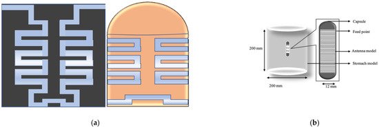
In [37], a U-shape meandered slot antenna was proposed for implant medical applications operated at 2.45 GHz. It is shown in Figure 6 that the antenna dimension decreased to W × L (29 × 35 mm2) from W × L (33 × 40 mm2) after the meandered slots insertion. The insertion of meandered/spiraling slots on the radiating patch results in incrementing the current path on the same antenna dimension. This increment of the current path can be utilized to minimize the antenna dimension. The meandered slot’s insertion on the radiating patch resulted in the enlargement of bandwidth from 384 MHz to 396 MHz, and the S11 parameter value improved to −43.72 dB from −23.22 dB. The authors of [38] proposed a meandered slot-shaped implant antenna, which is suitable for the medical device radio communications service (MICS) frequency band (401–406 MHz) applications (Figure 7). It was reported that the substrate dimension is reduced by 36.85% in length and 40% in width and the antenna was examined in an inhomogeneous human tissue environment. Furthermore, a capsule shape meandered slot antenna is proposed in [39,40,41,42] for implant endoscopy applications. The geometry of the capsule-shaped implant antennas operated at the MICS band and UWB are shown in Figure 8. The implant antenna dimension is reduced to 5.5 × 10 mm2 (Rc × Lc) in [39] and 6 × 36.2 mm2 (Rc × Lc) in [42] for altering rectangular antenna design to capsule shape design. Moreover, cylindrical and circular shapes with meandered slot dual-band (401–406 MHz and 2.4 MHz) implant antennas were proposed in [43,44].
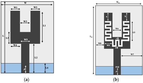
Figure 6. Implant antenna: without meandering slot (a) with meandering slot (b) [37].
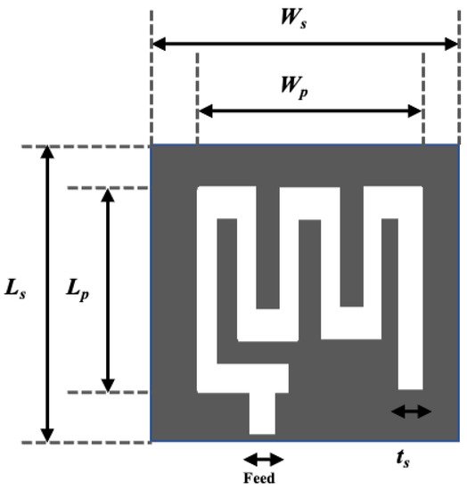
Figure 7. Meandered implant antenna proposed in [38].
1.2. Spiral Shape Radiating Patch
A spiral shape radiating patch is a useful antenna dimension miniaturization technique employed in [29,45,46,47,48,49]. Figure 9a illustrates a spiral shape implant antenna operated at 225–427 MHz with an equivalent homogeneous body model. The spiral shape helps to miniaturize the antenna dimensions to 17 × 17 × 18 mm3 compared with other antennas given in [29]. Two spiral shape implant antennas to occupy a small area of 6 × 5 × 0.3 mm3 [45] and 20 × 10 × 1.63 mm3 [46] operated at 2.4 GHz and 405 MHz, respectively are shown in Figure 9b,c. Several miniaturized dimensions with the spiral shape Complementary Split Ring Resonator (CSRR)-loaded implant antenna was reported in [47,48,49] for MICS applications.
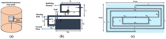
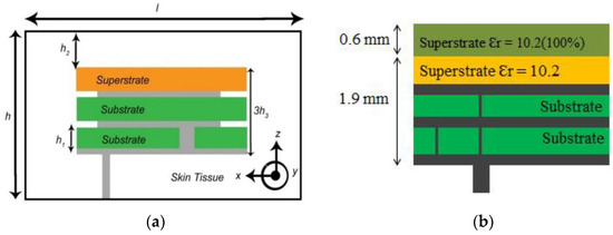
Antenna dimension can be miniaturized with the substrate material with higher relative permittivity suitable for wave propagation through the lossy medium. In the stacking patch layers technique, relative permittivity increases with the multi-layers dielectric substrate. Similarly, multi-layer dielectric element loading increases the current path, leading to a decrease of resonance frequency and the antenna dimension’s miniaturization. The stack patch implant antenna operated at the MICS frequency band used in [50,51] are shown in Figure 10a,b, respectively. As shown in Figure 10, two layers of substrate were inserted over the ground by putting a radiating patch in the middle and a superstrate layer placed over the final radiating patch. Consequently, the implant antenna dimension miniaturized to π × (7.5) 2 × 1.9 mm3 [51] and 10 × 10 × 2.01 mm3 [50], respectively. Besides, some other stack patch layers implant antennas are given in [52,53,54,55].
1.3. Insertion of Shorting Pin-In Wireless Technology
The Planar Inverted F-Antenna (PIFA) is a common example of a shorting pin antenna design technique. According to the PIFA theory, the shorting pin with antenna ground plan alter antenna resonance frequency from λ / 2 to λ / 4 . Spiral slot shape shorting pin antenna was employed in [56], where the antenna dimension was miniaturized to 149.6 mm3 compared with other antennas reported. Figure 11 illustrates a typical shorting pin PIFA antenna deployed in [57]. Besides, several miniaturized PIFA antennas were reported in [58,59,60,61,62,63,64].
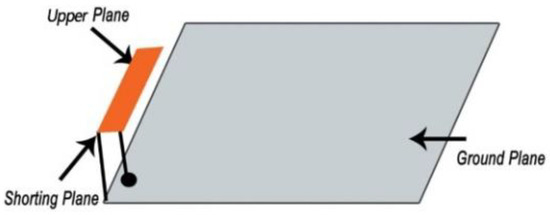
Figure 11. Typical shorting pin Planar Inverted F-Antenna (PIFA) antenna [57].
1.4. Gain and Efficiency Enlargement Technique
The absorption of radio wave frequency through the inhomogeneous lossy human body results in lower radiation efficiency. A significant amount of absorption happens due to the coupling with lossy tissue in the near reactive field. Recently, some implant antennas have been developed to solve low gain and efficiency problems. This section discusses some potential gain and efficiency enhancement techniques.
-
Insulating Layers: A theoretical calculation has been made in [65], where a multilayered insulation model considering fat and dry skin was taken as standard. Notably, the insulation with zirconia and 4 mm thickness around the implant antenna gave the lowest attenuation of 34.5 dB than the other insulation materials (e.g., alumina, polyamide, peek, polypropylene). This theoretical calculation agreed with the experimental results reported in [11]. Besides, several materials-based insulation models were investigated in [66,67,68,69,70,71] and the results showed that insulation for biocompatibility reduces the attenuation, while increasing gain and radiation efficiency.
-
Complimentary Split Ring Resonators (CSRRs) Antenna Model: The CSRR antenna model is an effective solution to enhance radiation efficiency and gain. This CSRR model compensates inductivity and electric field coupling with the near field due to the antenna’s negative permittivity [72,73]. The SAR is also reduced, which improves the radiation efficiency and gain. The CSRR implant antenna model for multiband (MICS, ISM, and 2.4 GHz) applications was designed and simulated in [74]. The simulation results showed that the electric field was at 403 MHz It can be noted that electric field absorption is reduced for the CSRR model compared to the non-CSRR model. Hence, radiation efficiency and gain are increased for all operational frequencies.
1.5. Bandwidth Enhancement Technique
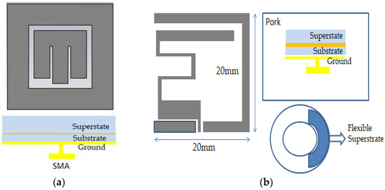
Deployment of wideband implant antennas in the medical frequency spectrum for biomedical telemetry applications is a research challenge. Typically, a parasitic patch is used as a traditional bandwidth enhancement (BW) technique [75], where a multi resonance mode was attained for square shape parasitic patches outside the main radiating patch. Hence, the bandwidth can be enhanced to 2.24–2.59 GHz using the multi resonance mode. Figure 12a illustrates the bandwidth enhancement technique via a loop shape parasitic patch [75], while Figure 12b shows a flexible structure bandwidth enhancement technique [76]. Because of the flexible structure, the antenna generated two coupling radiating patch structures with the ground. Hence, these two coupling structures attained 68% bandwidth applicable for the MICS frequency band.
1.6. Tuning Permanency Technique
The power absorption caused by the lossy environment around the implant antenna results in inefficient antenna operation. The implanted antenna is referred to as efficient when the operating frequency is tuned in a specific band area with efficient radiation efficiency. Even if antenna fundamentals state that the minimum antenna efficiency for 5G applications is 70%, it might vary depending on the appropriate implant applications. Recently, antenna designers have developed some techniques for tuning and impedance matching stability.
Planar antennas with a ground plane provide better tuning stability than antennas without a ground plane, such as loop and dipole antennas [77,78]. Besides, narrow operational bandwidth with a high superstrate biocompatibility system reduces the coupling with lossy tissue around the antenna, which leads to tuning stability and high radiation efficiency [77]. It is also found that the tuning of resonance frequency can be avoided if the antenna is operated on a wide frequency band [79,80].
2. Implant Antennas for Different Bio-Telemetry Applications
In this section, systems with implantable antennas for several biotelemetry applications, such as inside the human skull to monitor cerebrospinal fluid monitoring, blood pressure, and glucose level monitoring, will be summarized.
2.1. Implant Antenna for Monitoring of the Healing of Bone Fracture
The healing process of a fractured bone is a problematic biological process, and it requires continuous observation with mechanical support for the re-establishment of a fractured bone in its natural condition. The fractured bone restoration process varies between several weeks depending on age, the number of fractures, and bone location [81]. An implantable antenna with a bone healing mechanical system would be an excellent solution for continuous observation of fractured bones. This sub-section summarizes the implant antennas used for the robust bone restoration process.
In [81], an implant antenna system with two monopole antennas attached with a metal plate was proposed to observe the fractured bone restoration process. An artificial fracture bone phantom system where two monopole antennas were placed on both sides of the fracture is shown in Figure 13. The restoration process of a fractured bone was detected via the electric field distribution of the monopole antenna. Gabriel et al. [82] showed that relative permittivity and conductivity of blood are significantly higher than the bones across the radio frequency spectrum. It was mentioned that the higher conductivity and relative permittivity increase penetration loss, which reduces the electric field distribution of the propagation medium. In [81], the authors pointed out that the electric field distribution is substantially high when the bone damage is 0% compared with a fractured bone as shown in Figure 14. According to [83] the attenuation of the electric field in the Fresnel region is dependent on wave-number k for lossy medium, as stated by Equation (14). The wave-number k rely on relative permittivity ε r and conductivity σ as stated by Equation (15). Hence, higher values of the relative permittivity ( ε rblood = 58.1 , ε rbone = 11.3 ) and conductivity (σblood = 2.6, σbone = 0.4) in blood than bone constitutes a greater wave-number k for the fractured bone area, which leads to higher attenuation of the electric field in the fractured bone area due to the existence of blood. In conclusion, the reason behind the diversity of current distribution is due to the existence of blood in the bone fracture area, where there is no blood existence inside the restored fractured bone.
Electric field Attenuation = e − j kr / r
K = ω μ 0 μ r ε 0 ( ε r − j σ ω ε 0 )
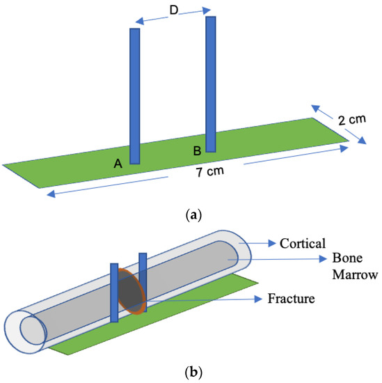
Figure 13. Implant antenna system for bone fracture restoration process. (a) Proposed monopole antenna, (b) monopole antenna position in artificial fracture bone phantom environment [81].
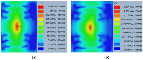
Figure 14. Electric field distribution at 1.8 GHz for 0% bone damage (a) and 100% fractured bone damage (b) [81].
A dual monopole antenna was proposed in [20] for monitoring the fracture of the bone, which was simulated with a voxel model of a 26-year-old female on CST Microwave Studio virtual version as shown in Figure 15. The restoration process of fractured bone was monitored by a monopole antenna placed on both sides of the fracture and determined the bone condition by transmitting power from one monopole to another monopole. It can be observed in Figure 16 that during the 0% bone damage period a widely distributed electric field was obtained, while the electric field distribution was consolidated in the recovery phase. The fabrication of the antenna system and observation of monopole antenna performance inside the bone fracture will be briefly discussed later.
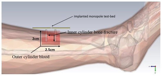
Figure 15. Simulating environment of monopole antenna in a fractured bone [20].
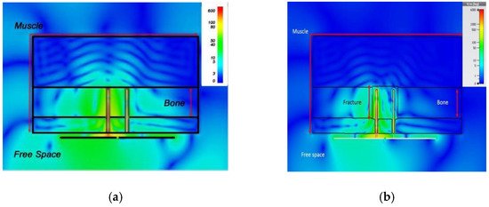
Figure 16. Electric field distribution at 2.5 GHz: during 0% bone damage period (a), fractured bone period (b) [20].
2.2. Implant Antenna for Glucose Level Monitoring in Blood
Glucose level monitoring in human blood plays an essential role in diagnosing life-threatening diseases (e.g., diabetes and hypoglycemia). Typically, chronic diabetic patients need to check blood samples daily to monitor glucose levels in the blood. The current method to check glucose levels is invasive and painful. Recently, implantable biosensors were developed to monitor glucose levels in the blood, which can provide a regular update about the glucose level of the diabetes patient.
An implantable bio-sensor system to monitor the glucose level in blood was implemented using a frequency shift mechanism [84]. The implantable antenna geometry, return loss, and resonance frequency shift of the implant antenna with the increment of glucose level in blood are shown in Figure 17. Furthermore, it is noted that the implant antenna obtained 40 MHz frequency shifting for glucose level fluctuation in blood between (120–530) mg/dL on blood mimicking phantoms and 26 MHz frequency shifting for glucose level fluctuation in pig blood between (67–490) mg/dL.
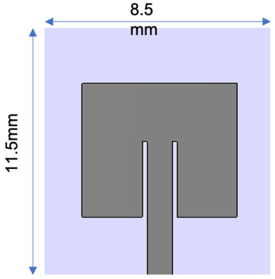
Figure 17. The glucose monitoring system in blood: geometry of implant antenna [84].
2.3. Implant Antenna for Diagnosing Brain Diseases
In diagnosing brain diseases and neurological disorders during therapy, an implantable wireless device and antenna will be a marvelous solution as upcoming medical technology. Nowadays, an implanted antenna is being used for restoring memory loss [67] and primary exposure of epileptic seizures. The basic mechanism of the wireless brain monitoring system is illustrated in Figure 18, where the implant antenna system contains a neural recorder that is connected with the transmitter system.
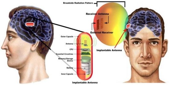
Figure 18. The basic mechanism of wireless brain monitoring system [85].
S. Hout and J. Chung in [85] reported a miniaturized circular shape implant antenna and the antenna was placed inside a seven-layer brain phantom as shown in Figure 18. Typically using a substrate with higher permittivity for miniaturizing antenna geometry results in a narrow bandwidth and lower radiation efficiency due to a high-quality factor [85]. Both of the substrate and biocompatible element with lower permittivity and dielectric constant substrate Taconic RF 3.5 ( ∈ r = 3.5 , Tan δ = 0.0018 ) were used to obtain a 14.9% increase in bandwidth compared to the previous implant antenna at 2.4 GHz shown in Figure 19b. However, omnidirectional radiation patterns can cause harmful side effects inside brain tissue due to the frequency dependence characteristic of human tissue [86]. To ensure patient safety, the implant antenna proposed in [85] achieved a radiation pattern in an optimistic direction shown in Figure 19c. The outside antenna receiver can efficiently communicate with the inside implant antenna. Finally, the antenna was fabricated and validated by injecting inside seven layers of artificial tissue emulating (ATE) materials brain phantom in an in vitro experiment, where the measurement agreed with the simulation results.
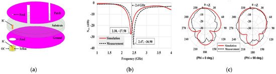
Figure 19. Geometry of implant antenna (a), antenna returns loss (b) and 2D radiation pattern (c) [85].
2.4. Implant Antenna for Blood Pressure Measurement
Frequent fall and rise of blood pressure can cause a stroke or severe cardiovascular disease for patients, and thus an accurate blood pressure measurement is critical to help medical personnel in managing several diseases that are related to blood pressure. Blood pressure measurement using an implantable antenna system inserted into the heart will be an excellent solution for heart patient monitoring. In [21], a pseudo normal mode helical antenna insulated by poly-di-methyl-siloxane (PDMS) layer is implemented and tested (Figure 20). The sensor and the implant antenna were put inside the left ventricle and experimented with a pig.
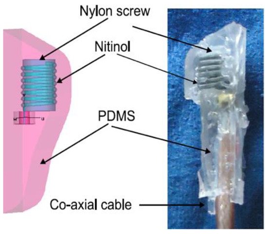
Figure 20. Snapshot of implant antenna for blood pressure measurement [21].
This entry is adapted from the peer-reviewed paper 10.3390/s21093163
This entry is offline, you can click here to edit this entry!